-
PDF
XC9500XL.pdf
family is a 3.3V CPLD family tion across multiple density options in a given package targeted for high-performance, low-voltage applications in footprint. leading-edge communications and computing systems, where high device reliability and low power dissipation is The XC9500XL architectural features
in „Oszilloskop mit AVR“ · Mikrocontroller und Digitale Elektronik ·
-
PDF
TE28F128J3D75.pdf
miniature card or SIMM module. The BYTE# signal allows either x8 or x16 read/writes to the device: • BYTE#-low enables 8-bit mode; address A0 selects between the low byte and high byte. • BYTE#-high enables16-bit operation; address A1 becomes the lowest order address and address A0 is not used (don’t care).
-
PDF
SW016_125kHz_reader_DSv2.5.PDF
powered, activation of SW016 will occur only when the host applies high level to ON pin. The host will turn SW016 in acquisition mode (reading) by applying a RESTART command of the type: low/high/low. All readings should start only after such pulsed reset. When a tag is
in „Kontaklose Chipkarten????“ · Mikrocontroller und Digitale Elektronik ·
-
PDF
SW016_125kHz_reader_DSv2.5.PDF
powered, activation of SW016 will occur only when the host applies high level to ON pin. The host will turn SW016 in acquisition mode (reading) by applying a RESTART command of the type: low/high/low. All readings should start only after such pulsed reset. When a tag is
in „Transponder Lesegerät SUCHE LÖSUNG ???“ · Mikrocontroller und Digitale Elektronik ·
-
PDF
integrated-device-technology-cv183-1apag_e89d53d904_1_.pdf
. Power on latch, HIGH = SRC5, LOW = CPU and PCI Stop#. 7 PCIF5/ITP_EN I/O 33.33MHz. Pin 46, 47 mode selection. Power on latch, HIGH = CPU_ITP, LOW = SRC8. 8 V S_PCI GND GND 9 VDD_48 PWR 3.3V 10 USB48/FS_A I/O 48MHz, frequency
in „Pin Mod IDT CV183-1APAG Taktgenerator“ · PC Hard- und Software ·
-
Datei
Drehzahlmesser2.asm
.def temp3 = r22 .def mc8u = r18 ;multiplicand .def mp8u = r19 ;multiplier .def m8uL = r20 ;result Low byte .def m8uH = r21 ;result High byte ldi temp1, HIGH (RAMEND) ;HIGH-Byte der obersten RAM-Adresse out SPH, temp1 ldi temp1, LOW(RAMEND) ;LOW-Byte der obersten RAM-Adresse out SPL, temp1 ldi temp1,
in „Drehzahlmesser mit ATmega 16“ · Mikrocontroller und Digitale Elektronik ·
-
Datei
Drehzahlmesser2.asm
=r16 .def temp2=r17 .def mc8u =r18 ;multiplicand .def mp8u =r19 ;multiplier .def m8uL =r20 ;result Low byte .def m8uH =r21 ;result High byte text: .db " RPM",0 ldi temp1, HIGH (RAMEND) ;HIGH-Byte der obersten RAM-Adresse out SPH, temp1 ldi temp1, LOW(RAMEND) ;LOW-Byte der obersten RAM-Adresse out SPL
in „Drehzahlmesser mit ATmega 16“ · Mikrocontroller und Digitale Elektronik ·
-
Datei
ENC28J60_INITIALISIERUNG.txt
--------------------------------------------------------- ; 'set receive pointer address ; Value = Low(rxstart_init) ; Call Enc28j60writecontrolregbyte(erxrdptl , Value) ; Value = High(rxstart_init) ; Call Enc28j60writecontrolregbyte(erxrdpth , Value) ; ldi temp1,(ERXRDPTL) ldi temp2,Low(rxstart_init
in „ENC28J60 Initialisierung ATmega1284P AVR Assembler Beispiele“ · Projekte & Code ·
-
Datei
MJoy.asm
ldi ZH, high(ThrottleAxisRAM) ldi ZL, low(ThrottleAxisRAM) ldi YH, high(ThrottleAxisEE) ldi YL, low(ThrottleAxisEE) call Init8AsymAxis ldi ZH, high(ZAxisRAM) ldi ZL, low(ZAxisRAM) ldi YH, high(ZAxisEE) ldi YL, low
in „IGOR USB lässt sich nicht assemblieren“ · Mikrocontroller und Digitale Elektronik ·
-
Datei
User_def_chars.asm
Codesegment .org 0x0000 ; Anfangsadresse bei Null ; rjmp hauptprogramm ; hauptprogramm: ldi temp, low(RAMEND) ; Stack initialisieren out SPL, temp ldi temp, high(RAMEND) ; nur bei AVR-MCUs mit out SPH, temp ; hoeherem Speicher als ATTiny2313 ser temp out DDRB, temp ; Port B Ausgang fuer LCD out portb
in „Lcd die 1000ste“ · Mikrocontroller und Digitale Elektronik ·
-
PDF
AN-1071_Class_D_Audio_Amplifier_Basics__IR.pdf
is in the way the MOSFETs are optimized. The Synch buck converter is optimized differently for the high and low side MOSFETs, with lower R for longer DS(on) duty and low Qg for short duty. The Class D amplifier has the same optimization for both of the MOSFETs, with the same R DS(on) for high and low
in „Regelung einer Sinuskurve per PWM“ · Mikrocontroller und Digitale Elektronik ·
-
PDF
0710.pdf
with this patented packaging configuration because the Hall from current conductor to die due to high dV/dt voltage transients elementissituatedinextremelycloseproximitytothecurrent to be measured. ▪Filter pin capacitor improves resolution in low bandwidth applications High level immunity to current
in „Stromsensor ACS710“ · Analoge Elektronik und Schaltungstechnik ·
-
Datei
init6963.c
| // | 1024 Bytes | // 1fffH +---------------+ void init_display(void) { // Set Control lines WR=HIGH ; CE=HIGH; RD=HIGH; CD=HIGH; RESET=LOW; delay_ms(100); RESET=HIGH; //reset must be high delay_ms(100); // Set Graphic Home Address write_data(LCD_GRAPHICS_HOME & 0xff); // Low BYte write_data(LCD_GRAPHICS_HOME
in „T6963 - Text wird nicht angezeigt“ · Mikrocontroller und Digitale Elektronik ·
-
Datei
20221021b-interrupt-Einspeise.ino
); pinMode(dcdcanpin,OUTPUT); digitalWrite(dcdcanpin,LOW); pinMode(elkoladepin,OUTPUT); digitalWrite(elkoladepin,HIGH); pinMode(ledpin,OUTPUT); pinMode(testxpin,OUTPUT); pinMode(testypin,OUTPUT); pinMode(testzpin,OUTPUT); ovlodrain = LOW; delay(2000); //
-
 Bild
Bild
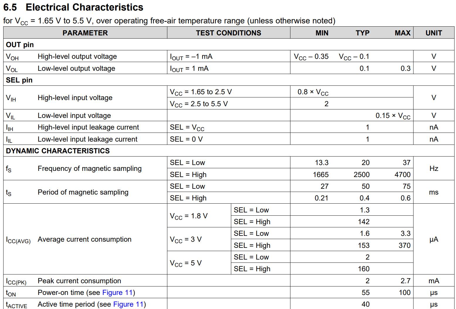
Tabelle der elektrischen Charakteristika eines Bauteils
VCC = 2.5 to 5.5 V 0.15 x VCC V IIH High-level input leakage current SEL = VCC 1 nA IIL Low-level input leakage current SEL = 0 V 1 nA DYNAMIC CHARACTERISTICS fs Frequency of magnetic sampling SEL = Low 13.3 20 37 Hz SEL = High 1665 2500 4700 ts Period of magnetic sampling SEL = Low 27 50 75 ms SEL = High 0.21 0.4 0.6 ICC(AVG) Average current consumption VCC = 1.8 V SEL = Low 1.3 uA SEL = High 142 VCC = 3 V SEL = Low 1.6 3.3 uA SEL = High 153 370 VCC = 5 V SEL = Low 2 uA SEL =
in „gute Suche nach Bauteilen bei Händlern“ · Offtopic · · Screenshots
-
Datei
lauflicht.txt
AtMega8 .equ c1 = 5000 ;Anzahl Durchläufe ldi r16, 0xFF ;Port D als Ausgang out DDRD, r16 ldi R25,HIGH(c1) ldi R24,LOW(c1) loop: sbi PORTD,0 sbiw R24,1 brne loop ldi R25,HIGH(c1) ldi R24,LOW(c1) loop1: cbi PORTD,0 sbi PORTD,1 sbiw R24,1 brne loop1 ldi R25,HIGH(c1) ldi R24,LOW(c1) loop2: cbi PORTD,1 sbi PORTD,2 sbiw R24,1 brne loop2 ldi R25,HIGH(c1) ldi R24,LOW(c1) loop3: cbi PORTD,2 sbi PORTD,3 sbiw R24,1 brne loop3 ldi R25,HIGH(c1) ldi R24,LOW(c1) loop4: cbi PORTD,3 sbi PORTD,4 sbiw R24,1 brne loop4 ldi R25,HIGH(c1) ldi R24,LOW(c1) loop5:
in „LED Lauflicht vereinfachen? AtMega8“ · Mikrocontroller und Digitale Elektronik ·
-
Datei
hx2262.c
setPinLow(); _delay_us( LONG_TIME ); setPinHigh(); _delay_us( SHORT_TIME ); setPinLow(); _delay_ms( LONG_TIME ); } void sendOne() { // Pegel am Ausgang 1 0 1 0 // Dauer kurz lang kurz lang setPinHigh(); _delay_us( SHORT_TIME ); setPinLow(); _delay_us( LONG_TIME ); setPinHigh(); _delay_us( SHORT_TIME ); setPinLow(); _delay_us( LONG_TIME ); } void sendFloat() { // Pegel am Ausgang 1 0 1 0 // Dauer kurz lang lang kurz setPinHigh(); _delay_us
in „Funksteckdosen HX2262 mit Atmega32 ansteuern“ · Mikrocontroller und Digitale Elektronik ·
-
Datei
OLED_Test.ino
SPI.transfer(0x10); // set higher column address to 0 digitalWrite(DC, HIGH); // write data for(col=0;col<131;col++) // clear page { SPI.transfer(0x00); } } digitalWrite(DC, LOW); // write commands SPI.transfer(0xaf); // Display on digitalWrite(CS, HIGH); // delay(150); digitalWrite(DC, LOW); // write commands digitalWrite(CS, LOW); SPI.transfer(0x02); // set lower column address to 2 SPI.transfer(0x10); // set higher column address to 0 SPI.transfer
in „SH1106 Init-Sequenz“ · Mikrocontroller und Digitale Elektronik ·
-
PDF
Nelson_Pass_Class-A_design_a40_OK.pdf
assures a higher concentration of low order distortions, 2nd and 3rd a few parts? In this case I have chosen two very effective approaches: harmonics and 1st and 2nd order intermodulations, giving them a constant current
in „MOSFET Class-A Endstufe, Ruhestrom Einstellung“ · Analoge Elektronik und Schaltungstechnik ·
-
PDF
ads830.pdf
INPUTS Logic Family CMOS/TTL Compatible Convert Command Start Conversion Rising Edge of Convert Clock High Level Input Current)(VIN= 5V) 100 µA Low Level Input Current IN = 0V) 10 µA High Level Input Voltage +2.4 V Low Level Input Voltage +1.0 V Input Capacitance 5 pF DIGITAL OUTPUTS Logic Family CMOS/TTL Compatible Logic Coding Straight Offset Binary Low Output Voltage (OL= 50µA) VDRV = 5V +0.1 V Low Output Voltage, (I = 1.6mA) +0.2 V OL High Output Voltage, OH = 50µA) +4.9 V High Output Voltage, OH = 0.5mA) +4.8 V Low Output Voltage, OL = 50µA) VDRV
in „USB Speicher-Oszilloskop (Anfängerhilfe)“ · Mikrocontroller und Digitale Elektronik ·
-
PDF
capsense-wp.pdf
transfer function, like Eo = C (area-linear), Eo = 1/C (spacing-linear). Use two balanced capacitors for high accuracy, with a transfer function like C1/C2 or (C1-C2)/(C1+C2) • Choose an excitation frequency high enough for low noise. As excitation frequency increases, external and circuit-generated noise decreases
in „Techniker-Projekt: Füllstandsanzeige für Modellfahrzeug“ · Mikrocontroller und Digitale Elektronik ·
-
PDF
PS-MPU-3300-00.pdf
the START condition (S) on the bus, which is defined as a HIGH-to-LOW transition of the SDA line while SCL line is HIGH (see figure below). The bus is considered to be busy until the master puts a STOP condition (P) on the bus, which is defined as a LOW to HIGH
in „SPI Kommunikation mit MPU3300“ · Mikrocontroller und Digitale Elektronik ·
-
PDF
Stochino_Power_Amp_300V_us_power.pdf
be influenced by the low, i.e. unity to two, output rates of change are to be expected. In current gain of the intermediate stage. This • to allow the use of low voltage high current order to produce comparable results, the
in „Audio-Endestufe - bitte um Erklärung der Funktion einer Teilschaltung“ · Analoge Elektronik und Schaltungstechnik ·
-
PDF
p2527-casiez.pdf
with an electrical cir- cuit, where a resistor in series with a capacitor defines a first decreases, a low-pass filter will have less lag than a high n order low-pass filter, ▯ can be computed as a function of the moving average filter. sampling period T and a time constant ▯, both expressed e Smoothing techniques
in „1€-Filter - Warum heißt der so?“ · Digitale Signalverarbeitung / DSP / Machine Learning ·
-
PDF
W25Q64FV.PDF
The /HOLD pin allows the device to be paused while it is actively selected. When /HOLD is brought low, while /CS is low, the DO pin will be at high impedance and signals on the DI and CLK pins will be ignored (don’t care). When /HOLD is brought high, device operation can resume. The /HOLD function can
-
PDF
tps62933-1.pdf
The device has an on-time extension function with a maximum on time of 7 μs (typical). During the low dropout O operation, the high-side MOSFET can turn on up to 7 μs, then the high-side MOSFET turns off and the low-side MOSFET turns on with a minimum off time of 140 ns (typical). It supports the maximum
in „TI Buck TPS62933.“ · Analoge Elektronik und Schaltungstechnik ·
-
PDF
SPOERLE__SAM7_Low-Cost_Entwicklungskit.pdf
SPOERLE Hot Offers: Sommeraktion: SAM7 Low-Cost Entwicklungskit Seite 1 von 1 Sommeraktion: SAM7 Low-Cost Entwicklungskit Atmel Corporation und SPOERLE ELECTRONIC bieten eine spezielle Sommeraktion für das preisgünstige ARM ® Entwicklungs-Kit
in „USB und AT91SAM7S64“ · Mikrocontroller und Digitale Elektronik ·
-
Datei
3Sensoren.c
PD3); } UART_send(fail_count); UART_send(status_reg); //status for diagnosis } //6. read out OUTZ high and low byte outZ_high = SPI_MasterRead(OUTZ_H, i); outZ_low = SPI_MasterRead(OUTZ_L, i); //put high and low byte in 16bit var outZ = (outZ_high << 8 + (outZ_low & 0xFF) ) >>4 ; //right adjusted 12bit in word //8bit bitmask and shifting to get 12bit right adjusted for UART transmission outZ_highUART = outZ_high >> 4; outZ_lowUART = (outZ_high << 4) | ((outZ_low & 0xFF) >> 4); //transmit, first high byte, then low byte UART_send( outZ_highUART ); UART_send( outZ_lowUART ); i++; } cli(); //disable
in „Beschleunigungssensor“ · Mikrocontroller und Digitale Elektronik ·
-
PDF
Arduino_Project_Handbook_25_Practical_Projects_to_Get_You_Started.pdf
(LED5, HIGH); } else { digitalWrite(LED5, LOW); } 60 • p roject 6 if (average > 550) { digitalWrite(LED6, HIGH); } else { digitalWrite(LED6, LOW); } if (average > 650) { digitalWrite(LED7, HIGH); } else { digitalWrite(LED7, LOW); } if (average > 750) { digitalWrite(LED8, HIGH); } else { digitalWrite(LED8, LOW); } if (average > 850) { digitalWrite(LED9, HIGH); } else { digitalWrite(LED9, LOW); } if (average > 950) { digitalWrite
in „LED Driver mit µC“ · Analoge Elektronik und Schaltungstechnik ·
-
PDF
MAX16832-MAX16832C.pdf
are at T = +25°C.)A X PARAMETER SYMBOL CONDITIONS MIN TYP MAX UNITS 1 DIM INPUT DIM Input-Voltage High VIH V IN - CS = 100mV 2.8 V 6 8 DIM Input-Voltage Low VIL V CS - VIN = 100mV 0.6 V 3 DIM Turn-On Time tDIM_ON V DIM rising edge to V LX < 0.5V IN 200 ns 2 DIM Input Leakage High V DIM = V IN 8 15 µA
in „MAX16832 v. ZXLD1362 (LED Treiber)“ · Mikrocontroller und Digitale Elektronik ·
-
PDF
AD7607.pdf
6 FRSTDATA - 9 0 Figure6.SerialReadOperation(Channel1) CS t8 t9 t 10 t11 t16 RD t 13 t14 t15 t17 HIGH LOW HIGH LOW DATA: DB[7:0] INVALID BYTE V1 BYTE V1 BYTE V8 BYTE V8 t 26 t27 t29 0 t24 6 FRSTDATA 0 0 Figure7.BYTEModeReadOperation Rev. B | Page 9 of 32 AD7607 Data Sheet ABSOLUTE MAXIMUM RATINGS TA
in „Unterschiedliches Verhalten innerhalb der gleichen IC-Reihe“ · Analoge Elektronik und Schaltungstechnik ·
-
PDF
SMB380_Preliminary_Datasheet_Rev13_20070918.pdf
Specification of four-wire SPI serial interface Interface parameters : Conditions Min. Typ. Max. unit Input - low level Vil_si Vddio=1.62V to 3.6V 0.3*Vddio V Input - high level Vih_si Vddio=1.62V to 3.6V 0.7*Vddio V Output – low level Vol_SDI Vddio=1.8V, iol=3 mA 0.4 V Output – high level Voh_SDI Vddio=1.8V, ioh
in „Problem SMB380“ · Mikrocontroller und Digitale Elektronik ·
-
Datei
goertzel.asm
(max 28 sonst Stack ueberlauf) ;***** Subroutine Register Variables .def mc16sL =r16 ;multiplicand low byte .def mc16sH =r17 ;multiplicand high byte .def mp16sL =r18 ;multiplier low byte .def mp16sH =r19 ;multiplier high byte .def m16s0 =r18 ;result byte 0 (LSB) .def m16s1 =r19 ;result byte 1 .def m16s2
in „CTCSS decoder / encoder“ · Mikrocontroller und Digitale Elektronik ·
-
PDF
K6T1008V2C_Samsungsemiconductor.pdf
tWP(1) WE DW tDH Data in Data Valid Data out High-Z High-Z NOTES (WRITE CYCLE) 1. A write occurs during the overlap of a CSw1, a high CS2and a low WE. A write begins at the latest transition amCSg1goes low, CS 2going high and WE going low: A write end at the earliest transition amoCS 1 going high, CS2 going low and WE going high, tWPis measured from the beginning of write to the end of write. 2. CW is measured from the CS 1going low or CS 2going high to the end of write. 3. AS is measured from
in „[V] 10St Samsung SRAM K6T10008V2V-GF-70 -128K X 8 Bit 3-3,6V“ · Markt ·
-
PDF
Serielle_Zweidraht_Schnittstelle.pdf
um beide Probleme zu lösen. Die seriellen Takte aller Master wird AND verknüpft übertragen , die High-Dauer des kombinierten Taktes ist gleich der vom Master mit der kürzesten abgegebenen High-Dauer. Die folgende Low-Dauer des kombinierten Taktes ist gleich der des Masters mit der längsten Low-Dauer. Beachten Sie, dass alle Master die SCL-Leitung abhören und wirksam beginnen, ihre SCL High und Low Time-out -Dauer zu zählen, wenn die gemeinsame SCL- Leitung High beziehungsweise Low wird. Schlichtung wird von allen Mastern ausgeführt . Sie überwachen die SDA-Leitung nach dem Ausgeben von
in „twi: wo ist das datenbyte?“ · Mikrocontroller und Digitale Elektronik ·
-
PDF
0401Koster58.pdf
VCO circuit. VDC, but becomes unstable at higher voltage values. This frequency range value of the feedback capacitor. If the ing range of the VCO depends on the seems to be the lower border of the test shunt capacitor is required, attention degree
-
PDF
Koster58_VFO.pdf
VCO circuit. VDC, but becomes unstable at higher voltage values. This frequency range value of the feedback capacitor. If the ing range of the VCO depends on the seems to be the lower border of the test shunt capacitor is required, attention degree
in „Clapp Oszillator mit oder ohne Bandpassfilter“ · HF, Funk und Felder ·
-
PDF
0401Koster58.pdf
VCO circuit. VDC, but becomes unstable at higher voltage values. This frequency range value of the feedback capacitor. If the ing range of the VCO depends on the seems to be the lower border of the test shunt capacitor is required, attention degree
in „LC Oszillator beliebige LC Verhältnisse“ · HF, Funk und Felder ·
-
PDF
RV-3032-C7_App-Manual-rev1.3.pdf
Interrupt Temperature Low Interrupt Temperature High Interrupt Divider Alarm Interrupt & Hours, Date Counter External Event Interrupt Temperature Low Interrupt Temperature High Interrupt External Event Interrupt Month, Year
in „ATtiny85 + Uhrenquarz mit 10 pF CL: Kondensatoren“ · Analoge Elektronik und Schaltungstechnik ·
-
Datei
avr300.asm
register empty i2c_write_first: breq i2c_get_ack ; goto get acknowledge sbi DDRD,SCLP ; force SCL low brcc i2c_write_low ; if bit high nop ; (equalize number of cycles) cbi DDRD,SDAP ; release SDA rjmp i2c_write_high i2c_write_low: ; else sbi DDRD,SDAP ; force SDA low rjmp i2c_write_high ; (equalize
-
Datei
avr300.asm
register empty i2c_write_first: breq i2c_get_ack ; goto get acknowledge sbi DDRD,SCLP ; force SCL low brcc i2c_write_low ; if bit high nop ; (equalize number of cycles) cbi DDRD,SDAP ; release SDA rjmp i2c_write_high i2c_write_low: ; else sbi DDRD,SDAP ; force SDA low rjmp i2c_write_high ; (equalize
in „I²C EEPROM am AVR“ · Mikrocontroller und Digitale Elektronik ·
-
Datei
AVR300.ASM
register empty i2c_write_first: breq i2c_get_ack ; goto get acknowledge sbi DDRD,SCLP ; force SCL low brcc i2c_write_low ; if bit high nop ; (equalize number of cycles) cbi DDRD,SDAP ; release SDA rjmp i2c_write_high i2c_write_low: ; else sbi DDRD,SDAP ; force SDA low rjmp i2c_write_high ; (equalize
in „I2C / TWI EEPROM 24C02B“ · Mikrocontroller und Digitale Elektronik ·
-
Datei
avr300.asm
register empty i2c_write_first: breq i2c_get_ack ; goto get acknowledge sbi DDRD,SCLP ; force SCL low brcc i2c_write_low ; if bit high nop ; (equalize number of cycles) cbi DDRD,SDAP ; release SDA rjmp i2c_write_high i2c_write_low: ; else sbi DDRD,SDAP ; force SDA low rjmp i2c_write_high ; (equalize
in „I2C Read Byte Problem in ASM“ · Mikrocontroller und Digitale Elektronik ·
-
Datei
AVR300.ASM
register empty i2c_write_first: breq i2c_get_ack ; goto get acknowledge sbi DDRD,SCLP ; force SCL low brcc i2c_write_low ; if bit high nop ; (equalize number of cycles) cbi DDRD,SDAP ; release SDA rjmp i2c_write_high i2c_write_low: ; else sbi DDRD,SDAP ; force SDA low rjmp i2c_write_high ; (equalize
in „I²C über SPI an ATtiny ?“ · Mikrocontroller und Digitale Elektronik ·
-
Datei
avr300.asm
register empty i2c_write_first: breq i2c_get_ack ; goto get acknowledge sbi DDRD,SCLP ; force SCL low brcc i2c_write_low ; if bit high nop ; (equalize number of cycles) cbi DDRD,SDAP ; release SDA rjmp i2c_write_high i2c_write_low: ; else sbi DDRD,SDAP ; force SDA low rjmp i2c_write_high ; (equalize
in „1-Wire auf einem AVR mit Assembler“ · Mikrocontroller und Digitale Elektronik ·
-
Datei
avr300_I2C__Single__Master_Implementation.asm
register empty i2c_write_first: breq i2c_get_ack ; goto get acknowledge sbi DDRD,SCLP ; force SCL low brcc i2c_write_low ; if bit high nop ; (equalize number of cycles) cbi DDRD,SDAP ; release SDA rjmp i2c_write_high i2c_write_low: ; else sbi DDRD,SDAP ; force SDA low rjmp i2c_write_high ; (equalize
in „LCd Initialisierung schlägt fehl“ · Mikrocontroller und Digitale Elektronik ·
-
PDF
T83C5121.PDF
1 1 1 0 2 1 1 3 (Highest) 47 4164G–SCR–07/06 A low-priority interrupt can be interrupted by a high priority interrupt, but not by another low-priority interrupt. A high-priority interrupt can’t be interrupted by any other
in „[V] 1 Stange ältere (ca. 56St) Atmel AT89C5121 mit Interface für Chipkarten/ SIM (9€)“ · Markt ·
-
PDF
T83C5121.PDF
1 1 1 0 2 1 1 3 (Highest) 47 4164G–SCR–07/06 A low-priority interrupt can be interrupted by a high priority interrupt, but not by another low-priority interrupt. A high-priority interrupt can’t be interrupted by any other
in „[V] noch 1 Stange ältere (60St) Atmel AT89C5121 mit Interface für Chipkarten/ SIM (9€)“ · Markt ·
-
PDF
AN332.pdf
has not fallen below SNR low threshold. 1 = Received SNR has fallen below SNR low threshold. 1 1 RSSIHINT RSSI Detect High. 0 = RSSI has not exceeded above RSSI high threshold. 1 = RSSI has exceeded above RSSI high threshold. 1
in „Radioempfang: Mono statt Stereo erzwingen, UKW“ · HF, Funk und Felder ·
-
PDF
doc4113.pdf
PSH PSLPriority Level 0 0Lowest 4 PSH 0 1 1 0 1 1Highest Timer 1 overflow interrupt priority high bit PT1HPT1LPriority Level 3 PT1H 0 0 Lowest 0 1 1 0 1 1Highest External interrupt 1 priority high bit PX1HPX1LPriority Level 0 0Lowest 2 PX1H 0 1 1 0 1 1Highest Timer 0 overflow interrupt priority high bit PT0HPT0LPriority Level 0 0Lowest 1 PT0H 0 1 1 0 1 1Highest External interrupt 0 priority high bit PX0H PX0LPriority Level 0 PX0H 0 0Lowest 0 1 1 0 1 1Highest
in „STC12C5A60S2 (a.k.a 80C51) programieren mit mySmartUSB light“ · Mikrocontroller und Digitale Elektronik ·