-
Datei
IRremote.cpp
number of microseconds. // A space is no output, so the PWM output is disabled. TIMER_DISABLE_PWM; // Disable pin 3 PWM output delayMicroseconds(time); } void IRsend::enableIROut(int khz) { // Enables IR output. The khz value controls the modulation frequency
in „IR library auf Atmega328 8Mhz“ · Mikrocontroller und Digitale Elektronik ·
-
PDF
HY-LandTiger_SCH.pdf
P3.26 SDA P0.28 24 P0.27/SDA0/USB_SDA 75 P2.0 P2.0 26 27 P3.25 SCL P0.29 29 P0.28/SCL0/USB_SCL P2.0/PWM1.1/TXD1 74 P2.1 DB00 P2.1 27 28 3V3 USB_D+ P0.30 30 P0.29/USB_D+ P2.1/PWM1.2/RXD1 73 P2.2 DB01 P2.2 28 29 P0.29 USB_D- P0.30/USB_D- P2.2/PWM1.3/CTS1/TRACEDATA3 70 P2.3 DB02 GND 29 30 P0.30 TDO 1 P2.3/PWM1.4/DCD1/TRACEDATA2 69 P2.4 DB03 3V3 30 TDO TDO/SWO P2.4/PWM1.5/DSR1/TRACEDATA1 DB04 31 GND TDI TDI 2 TDI P2.5/PWM1.6/DTR1/TRACEDATA0 68 P2.5 DB05 P2.3 31 32 P1.18 TMS TMS 3 TMS/SWDIO P2.6/PCAP1.0/RI1
-
 Bild
Bild
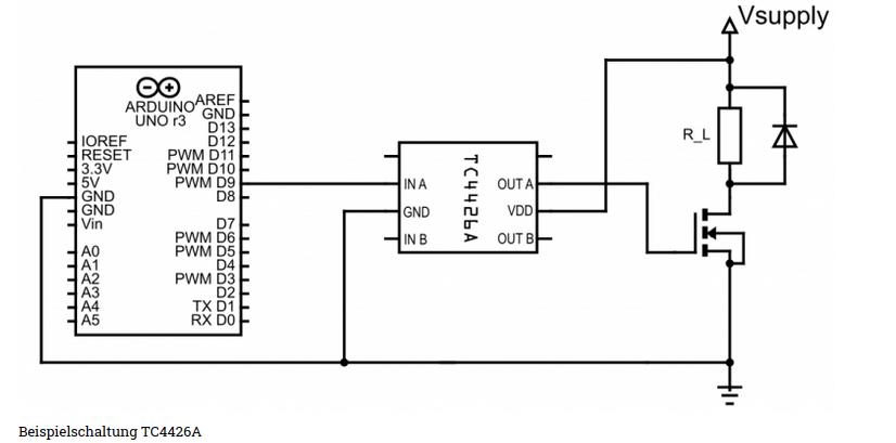
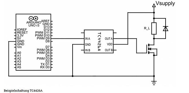
Schaltplan mit Arduino Uno und TC4426A Treiber
ARDUINO UNO r3, AREF, GND, D13, D12, PWM D11, PWM D10, PWM D9, D8, D7, PWM D6, PWM D5, D4, D2, TX D1, RX D0, A0, A1, A2, A3, A4, A5, Vin, GND, 5V, 3.3V, RESET, IOREF, TC4426A, IN A, GND, IN B, OUT A, VDD, OUT B, R_L, Vsupply, Beispielschaltung
in „IGBT Modul SKM150GAL12T4 brennt durch“ · Analoge Elektronik und Schaltungstechnik · · Schaltpläne
-
PDF
ADCINC.pdf
negative input. If single-ended input is desired, set this value to “Discon- nected”. PulseWidth Allows PWM pulsewidth to set from a value 1 to 255 counts. If no value is set then the user module automatically sets the PWM pulsewidth to 1 when the GetSamples function is called. PWM Output The Output parameter
in „Beispiel Anwendungen/Application zu ADCs - Abtastrate & Auflösung“ · Mikrocontroller und Digitale Elektronik ·
-
 Bild
Bild
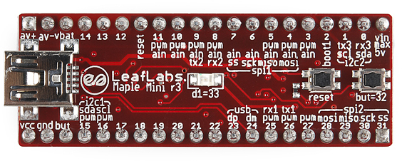
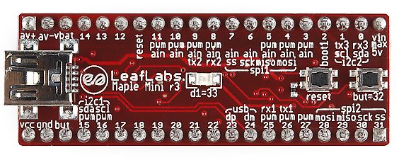
LeafLabs Maple Mini r3 Mikrocontroller-Platine
LeafLabs Maple Mini r3 av+ av-vbat 14 13 12 reset pwm ain tx2 rx2 ss sck miso mosi boot1 tx3 rx3 vin max 5v sda i2c d1=33 but=32 reset usb dp dm pwm pwm pwm mosi miso sck ss 23 24 25 26 27 28 29 30 31 22 21 20 19 18 17 16 15 vcc gnd but i2c1 sdasc1 pwm
in „[S] Maple Mini STM32 Bords“ · Markt · · Platinenfotos
-
Datei
avr.txt
------------------------------------- TCCR1A Timer/Counter1 Control Register A 7 6 1 0 COM11 COM10 PWM11 PWM10 0 0 an OC1 passiert garnichts 0 1 an OC1 wird gewechselt von 0 zu 1 bzw. 1 zu 0 1 0 an OC1 ist logisch 0 1 1 an OC1 ist logisch 1 0 0 PWM ausgeschaltet 0 1 8-Bit PWM 1 0 9-Bit PWM 1 1 10-Bit
-
Datei
Wie_sag_ich_es_dem_AVR.txt
------------------------------------- TCCR1A Timer/Counter1 Control Register A 7 6 1 0 COM11 COM10 PWM11 PWM10 0 0 an OC1 passiert garnichts 0 1 an OC1 wird gewechselt von 0 zu 1 bzw. 1 zu 0 1 0 an OC1 ist logisch 0 1 1 an OC1 ist logisch 1 0 0 PWM ausgeschaltet 0 1 8-Bit PWM 1 0 9-Bit PWM 1 1 10-Bit
in „Assembler Sprache erlernen“ · Mikrocontroller und Digitale Elektronik ·
-
Datei
report_synth.txt
(pwm_lights_0/USER_LOGIC_I/count<24>) LUT2:I0->O 2 0.704 0.451 pwm_lights_0/USER_LOGIC_I/PWM_value<6>54 (pwm_lights_0/USER_LOGIC_I/PWM_value<6>54) LUT4:I3->O 1 0.704 0.424 pwm_lights_0/USER_LOGIC_I/PWM_value<6>94_SW0 (N16) LUT4:I3->O 1 0.704 0.595 pwm_lights_0/USER_LOGIC_I/PWM_value<6>94 (pwm_lights_0/USER_LOGIC_I/PWM_value<6>) LUT2:I0->O 1 0.704 0.000 pwm_lights_0/USER_LOGIC_I/Mcompar_LEDs_cmp_ge0000_lut<6> (pwm_lights_0/USER_LOGIC_I/Mcompar_LEDs_cmp_ge0000
in „Place and Route partially locked IO bus“ · FPGA, VHDL & Co. ·
-
Datei
system.c
STATE_IDLE; // Initialisiere I2C i2c_readaddr_init(); init_twi_slave(i2c_readaddr()); // Initialisiere PWM Channels channels_init(); // Initialisiere PWM Timer pwmtimer_init(); // Initialisiere PWM Modes modes_init(); softreset = 0; // Enable Watchdog wdt_enable(WDTO_2S); // EEPROM if (getEEDefaultExist(
in „Wie macht man solche Lichtmodes? Lauflicht, PWM und Co“ · Mikrocontroller und Digitale Elektronik ·
-
Datei
Aqua_1.txt
Timer 0 Interrupt AANFANG ******************************************/ ISR (TIMER0_OVF_vect) { // Soft PWM für LED 0 if (pwmcounter0<=pwmlaufvar0 && pwmstart0==true) { pwmgest0=true; // PWM läuft! LED0_ON; } else { LED0_OFF; } if (pwmcounter0>=255) { pwmcounter0=0; } else { pwmcounter0++; } if (pwmlaufvar0
in „Atmega8 PORTB“ · Mikrocontroller und Digitale Elektronik ·
-
PDF
TMS320F2812_Datasheet.pdf
CAP5 M SPISIMOA XA[1] XRD PWM12 _QEP3 _QEP4 TEST1 XD[9] X2 VSS XA[3] PWM1 SCIRXDB PWM2 L V V XD[6] PWM11 XD[7] C5TRIP V TDIRB XD[10] V V PWM3 PWM4 XD[12] DD SS DDIO DDIO SS K VSS SPICLKA XD[4] SPISTEA T3PWM VSS C6TRIP TCLKINB X1
in „Wieder eine Elektronik-Anfängerfrage“ · Mikrocontroller und Digitale Elektronik ·
-
PDF
pic18f2320.pdf
, 2V - PWM output: PWM resolution is 1 to 10-bit - PRI_IDLE: 37 µA, 1 MHz, 2V Enhanced Capture/Compare/PWM (ECCP) module: - SEC_RUN: 14 µA, 32 kHz, 2V - One, two or four PWM outputs - SEC_IDLE: 5.8 µA, 32 kHz,
in „I2C-Bus Collision“ · Mikrocontroller und Digitale Elektronik ·
-
 Bild
Bild
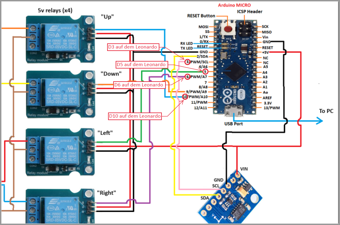
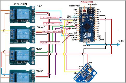
Verdrahtungsschema Arduino Leonardo mit vier Relaismodulen
ICSP Header MOSI SS SCK MISO 1/TX 0/RX Vin GND RESET D3 auf dem Leonardo RX LED 2/SDA TX LED GND 3/PWM/SCL 4/AG 5 D5 auf dem Leonardo 6/PWM/A7 A5 A4 A3 A2 A1 Ao AREF 3.3V 7 D6 auf dem Leonardo 8/A8 9/PWM/A9 A9 10 D10 auf dem Leonardo 11/PWM 10 A10 12/A11 A11 13/PWM USB Port To PC "Down" "Left" "Right
in „Allgemeine Grundfragen Sat-Rotoren bei 0°/360° Durchlauf“ · HF, Funk und Felder · · Diagramme
-
 Bild
Bild
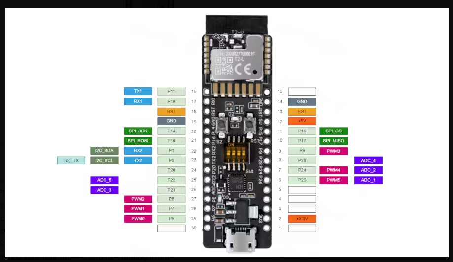
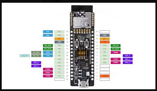
Pinbelegung eines Mikrocontroller-Moduls
SPI_SCK P14 20 SPI_MOSI P16 21 I2C_SDA RX2 P1 22 Log TX I2C_SCL TX2 P0 23 ADC_5 P20 24 ADC_3 P22 25 PWM2 P23 26 PWM1 P8 27 PWM0 P7 28 P6 29 30 15 14 GND 13 RST 12 +5V 11 SPI_CS P15 10 SPI_MISO P17 9 PWM3 P9 8 ADC_2 P28 7 PWM4 P26 6 ADC_1 P24 5 4 3 +3.3V 2 1
in „Espressif-Verfügbarkeitsgarantie für ESP8266, Quadband-GNSS-Modul, mehr Embedded-Python uvam“ · Mikrocontroller und Digitale Elektronik · · Screenshots
-
PDF
081_TK_RGB_Matrix_Control_Propeller_1.pdf
Ctrl. cog internal Mem 192 Bytes Sync UART Ctrl. serial Bus Timings: 100Hz refresch rate 192 Channel PWM with Display Muxing Rate: 1/8 PWM Depth 256steps each cog: 32 Pixel in one 10ms timeslot or: 4 pixel in a 1,25ms Timeslot -> in einem Zeitabschnitt von 10ms müssen 192soft pwm 256mal berechnet werden. -> 0.01 / (192*256)=0.2034us für eine pwm ->für eine zeile: 256*24*0.2034= 1,25ms->ok bei 20mhz sind es grob 4 takte für die berechnung und ausgabe einer pwm…. Hardware Examples Modulverschaltung: Lösung mit CPLD
in „LED-Matrix, 9x9 RGB, Voll dimmbar“ · Mikrocontroller und Digitale Elektronik ·
-
PDF
081_TK_RGB_Matrix_Control_Propeller_1.pdf
Ctrl. cog internal Mem 192 Bytes Sync UART Ctrl. serial Bus Timings: 100Hz refresch rate 192 Channel PWM with Display Muxing Rate: 1/8 PWM Depth 256steps each cog: 32 Pixel in one 10ms timeslot or: 4 pixel in a 1,25ms Timeslot -> in einem Zeitabschnitt von 10ms müssen 192soft pwm 256mal berechnet werden. -> 0.01 / (192*256)=0.2034us für eine pwm ->für eine zeile: 256*24*0.2034= 1,25ms->ok bei 20mhz sind es grob 4 takte für die berechnung und ausgabe einer pwm…. Hardware Examples Modulverschaltung: Lösung mit CPLD
in „RGB 8x8 LED Matrix 100HZ 8Bit PWM“ · Mikrocontroller und Digitale Elektronik ·
-
 Bild
Bild
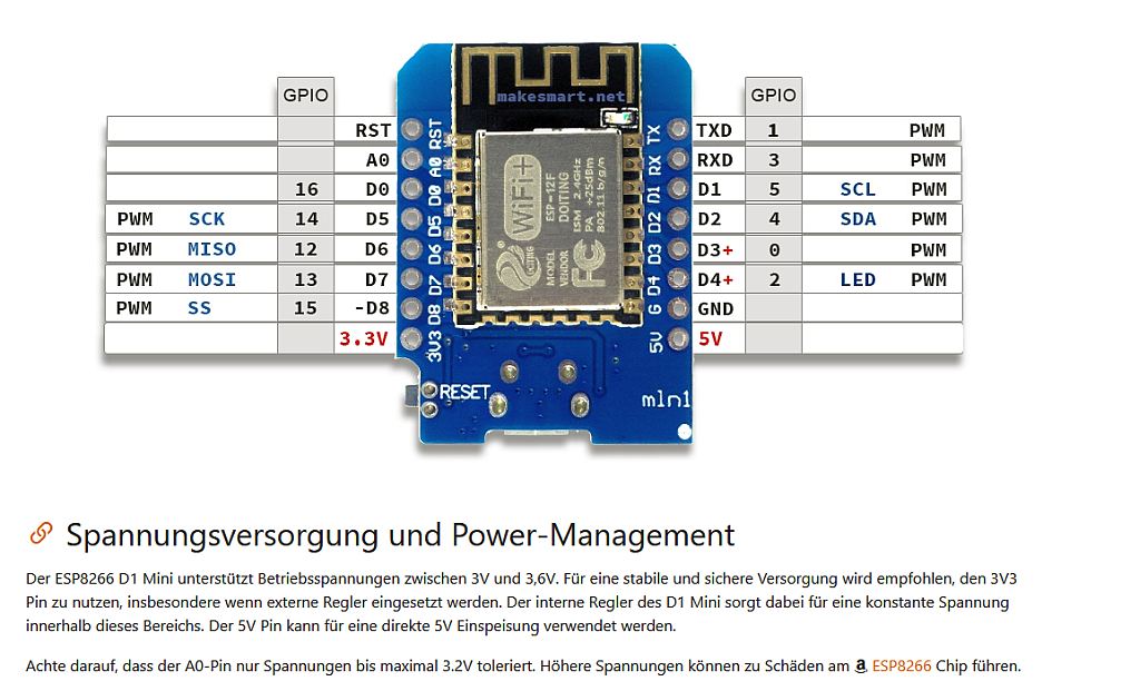
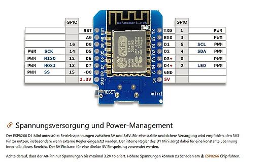
ESP8266 D1 Mini Pinbelegung und Spannungsversorgung
GPIO RST TXD PWM A0 D0 PWM 16 SCK D5 PWM 14 MISO D6 PWM PWM MOSI D7 D2 4 SDA D7 D4 2 LED SS -D8 6 D3 GND 3V3 5V RESET mlnl Spannungsversorgung und Power-Management Der ESP8266 D1 Mini unterstützt Betriebsspannungen
in „ESP8266 D1 Mini + Relaismodul: Relais bleibt bei D1 dauerhaft eingeschaltet“ · Mikrocontroller und Digitale Elektronik · · Screenshots
-
 Bild
Bild
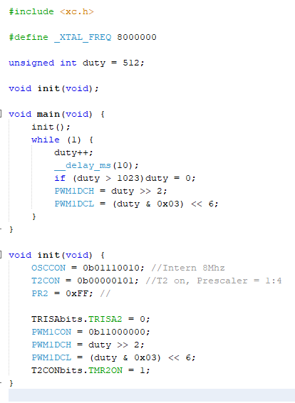
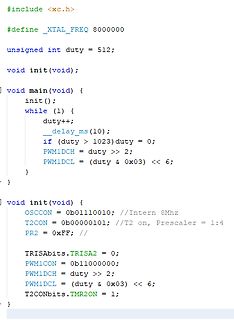
C-Quellcode für PWM-Steuerung auf Mikrocontroller
init(void); void main(void) { init(); while (1) { duty++; __delay_ms(10); if (duty > 1023) duty = 0; PWM1DCH = duty >> 2; PWM1DCL = (duty & 0x03) << 6; } } void init(void) { OSCCON = 0b01110010; //Intern 8Mhz T2CON = 0b00000101; //T2 on, Prescaler = 1:4 PR2 = 0xFF; // TRISAbits.TRISA2 = 0; PWM1CON = 0b11000000; PWM1DCH = duty >> 2; PWM1DCL = (duty & 0x03) << 6; T2CONbits.TMR2ON = 1;
in „PWM mit PIC12F1501“ · Mikrocontroller und Digitale Elektronik · · Screenshots
-
PDF
M37560_Prozessor.pdf
f(IN) = 8 MHz) Fig. 36 Timing of PWM cycle Data us PWM PWM PWM 1function prescaler pre-latch register pre-latch enable bit Transfer control circuit Port 51 PWM PWM lacth prescaler latch register latch Count source P 51/PWM 1 selection
in „M37560 (Buderus-Steuerung) puffern“ · Mikrocontroller und Digitale Elektronik ·
-
Datei
m8515.asm
.include "m8515def.inc" .def tmp = R16 .def sek = R17 .def min = R18 .def hour = R19 .def pwmA = R20 .def pwmB = R21 .def sys_frame = R22 .def rx_ptr = R23 .def led_out = R24 .def status = R25 .equ uart_rx_buf = 0x0060 .equ uart_tx_buf = 0x0070 .equ b_to_a_tmp = 0x0090 .equ uart_cmd_c = 0 .equ
-
Datei
fptest10.asm
******************************************************************** ;* * ;* Testprogramm variable PWM * ;* * ;* Controller: 8515 Clock = 4 MHz * ;* * ;* * ;* Stand: 25.5.03 * ;* * ;* PWM Variabel,Frequenz variabel * ;* * ;* Rechenroutine zur Bestimmumg des Puls / Pausenverhältnisses aus * ;* gewählter
in „Allgemeine Fragen zu PWM“ · Mikrocontroller und Digitale Elektronik ·
-
Datei
isrs.S
// ISRs for FireFly project #include <avr/io.h> #define FLAG_WAVE 0 // PWM is active for a LED #define FLAG_TIMER 1 // PWM is active #define FLAG_UPDATE 2 // Watchdog signaled a update #define SIZEOF_FLY 10 // sizeof struct firefly_t #define WAVE_END_L 0 // offsets to members
in „Glühwürmchen in Rotkohlglas gefangen“ · Projekte & Code ·
-
PDF
HV9901.pdf
voltages up to 240V. Current The HV9901 has an internal high-voltage regulator to power ❐ Efficient PWM Operation Using the Relay Coils’ Inductance internal PWM circuitry. Additionally it includes an adjustable auxiliary regulator with a 1mA capability that can be used to supply low power microcontrollers
in „Cree LED an 230V“ · Mikrocontroller und Digitale Elektronik ·
-
Datei
main.c
; P1SEL |= 0x04; // P1.3 TA1/2 options TACCR0 = 10; // PWM Period TACCTL1 = OUTMOD_7; // TACCR1 reset/set TACCR1 = 2; // TACCR1 PWM duty cycle TACTL = TASSEL_1 + MC_1; // TIMER A, ACLK, up mode P1IFG &= ~0x02; // P1.2 IFG cleared P1IFG &= ~0x01; // P1.0 IFG
in „MSP430 Timer inkompatibel mit ADC“ · Mikrocontroller und Digitale Elektronik ·
-
Datei
main.c
PWM: set at BOTTOM, clear at match // COM1A1/B1 COM1A0/B0 // 1 0 // // configure PWM for analogue outputs: P_ANA_01, P_ANA_02 TCCR0A = (1 << COM0A1) | (1 << COM0B1) | (1 << WGM00 ); TCCR0B = (1 << CS01 ); // configure PWM for analogue outputs: P_ANA_03, P_ANA_04 TCCR1A = (1 << COM1A1) | (1 << COM1B1) | (1 << WGM10 ); TCCR1B = (1 << CS11 ); // configure PWM for analogue outputs: P_ANA_05, P_ANA_06 TCCR2A = (1 << COM2A1
in „selbstdefiniertes Zeichen wird am LCD nicht richtig ausgegeben“ · Mikrocontroller und Digitale Elektronik ·
-
Datei
regelung5a.c
0.01) yn = 0.01; // Begrenzung auf 0.01 .. 0.99 if (yn > 0.99) yn = 0.99; /* Stellgröße y ausgeben = PWM-Schwelle setzen */ tmp1 = (uchar)(yn * 256); // Vergleichswert für 8bit PWM OCR1A = tmp1; // für PWM-Ausgabe auf CIF 1.3 auf Oszi; OCR1B = tmp1; // Motoransteuerung über Schalteinheit wait_us(100);
in „Drehzahlregelung einer Handbohrmaschine“ · Mikrocontroller und Digitale Elektronik ·
-
Datei
Code_ePWM1_with_Adc.txt
// Included Files #include "driverlib.h" #include "device.h" // #define EPWM_TIMER_TBPRD 166U // PWM Frequenz 300Khz für alle ePWMs #define Dead_Band_FED 10U // dead band FED, Totzeit im Fallingedge von 50ns #define Dead_Band_RED 10U // dead band RED, Totzeit im Risingedge von 50 ns // Globals float
in „frage zu C2000 F280049C von Ti mit CCS programmieren“ · Mikrocontroller und Digitale Elektronik ·
-
Datei
PWM_PA0_Uvergleich-3.9khz-IRQ3.asm
;ausgangsspannungsregelung nach stepdown ;pwm an atmega16 für 3,906 khz ;bei 4mhz taktfrequenz ;mit timer0 im fast pwm mode, 8 bit aufloesung ;pwm-signal liegt auf pb3 oc0 ;13.2.12 .include "m16def.inc" ;.def v_panel = r14 ;Messwert PV-Spannung
in „Hilfe Ladereglung Atmega16 Assembler“ · Mikrocontroller und Digitale Elektronik ·
-
Datei
regler_sensor.c
TIMER 0 initialisation ****************************************/ //Set Force Output Compare to 0 -> PWM mode******************** TCCR0|=(0<<FOC0); //PWM, Phase Correct******************************************* TCCR0|=(0<<WGM01); TCCR0|=(1<<WGM00); //Clear OC0 on compare match when up-counting. Set OC0
in „LCD Display funktioniert bei Zusammenstellung nicht“ · Mikrocontroller und Digitale Elektronik ·
-
 Bild
Bild
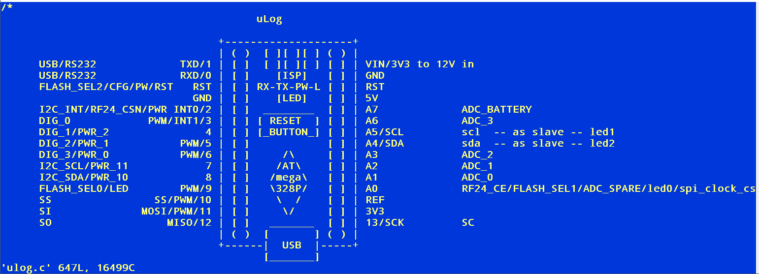
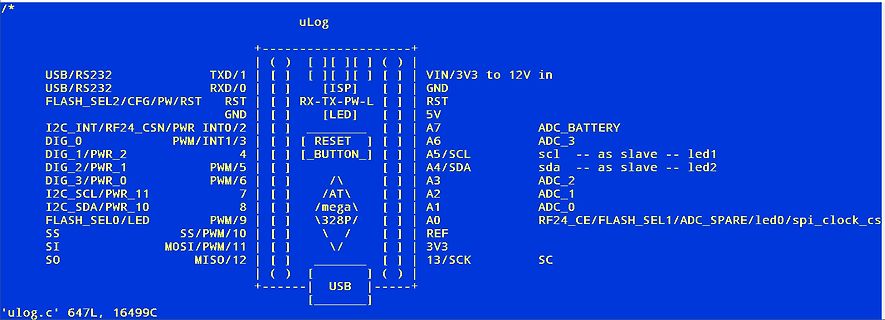
Pinbelegung einer uLog-Platine
uLog USB/RS232 TXD/1 USB/RS232 RXD/0 FLASH_SEL2/CFG/PW/RST RST GND I2C_INT/RF24_CSN/PWR INT0/2 DIG_0 PWM/PWR_2 DIG_1/PWR_0 PWM/5 I2C_SCL/PWR_11 PWM/6 I2C_SDA/PWR_10 7 SS SS/PWM/10 8 SI MOSI/PWM/11 9 SO MISO/12 VIN/3V3 to 12V in GND RST 5V A7 ADC_BATTERY A6 ADC_3 A5/SCL scl -- as slave -- led1 A4/SDA sda
in „Datenlogger mit ca. 1ksps“ · Markt · · Screenshots
-
Datei
Noname.map.txt
/pwm_curr_fdbk.o .text.PWMC_RegisterSwitchonPwmCallBack 0x0000000000000000 0x4 Middlewares/MotorControl/pwm_curr_fdbk.o .text.PWMC_RegisterReadingCalibrationCallBack 0x0000000000000000 0x4 Middlewares/MotorControl
in „Problem mit STM32F103 und RAM-Größe“ · Mikrocontroller und Digitale Elektronik ·
-
Datei
DCF_Decoder.vhd
IEEE; use IEEE.STD_LOGIC_1164.ALL; use IEEE.STD_LOGIC_ARITH.ALL; use IEEE.STD_LOGIC_UNSIGNED.ALL; -- PWM Dekodierung PWM Signal entity PWM_Decoder is port ( DCF_Sync_Sig, Local_CLK : in bit; bit_clk, min_clk, data_bit : out bit ); end PWM_Decoder; architecture Decoder of PWM_Decoder is -- Signale und Deklaratioenen
-
PDF
SIM800_Hardware_Design_V1.09.pdf
MHz ADC precision 10 30 mV Note: the voltage should less than 2.8V, or the ADC may be damaged. 4.15. PWM Table 25: Pin definition of the PWM Pin name Pin number Description PWM0 35 PWM0 PWM1 36 PWM1 Note: SIM800 can only support 1 PWM synchronously, if customer set PIN 35 as PWM, so PIN36 can only be used
in „SIM800L Verbindung instabil“ · Mikrocontroller und Digitale Elektronik ·
-
PDF
40146F.pdf
Number Symbol Bit Description 0 BACW Blank Alternate Code Word 1 BSEL Baud Rate Selection TABLE 3-1: PWM OPTIONS 2 TXWAK PWM mode: 1/6, 2/6 or 1/3, MOD TXWAK BSEL TE Duty Cycle 2/3 select VPWM mode: Wake-up 0 0 0 400us 1/3-2/3 enable 0 0 1 200us 1/3-2/3 3 SPM Sync Pulse Modulation 0 1 0 200us 1/6-2/6 4
in „Fehlersuche Funksender Zentralverriegelung Toyota Yaris“ · Fahrzeugelektronik ·
-
PDF
SG3525ANG.pdf
pulses. Vref 16 Reference Regulator 15 V CC Clock 0.1 0.1 4 Flip/ 13 VC Flop 3.0k Sync 0.1 3 O Out A PWM s 11 ADJ. RT c A 1.0k 6 i l 1.5k Deadtime l 1.0k, 1.0W a 0.009 Ramp 7 t (2) 100▯ o 5 r 14 0.1 0.001 B Out B Comp 10k 9 12 1 = V PWM GND IO 0.01 2 = 1(+) 50▯A Softstart 3 = 1(-) 1 8 1 + 2 2 1 5.0▯F -
in „Gegentaktwandler Überschwingen im Leerlauf“ · Analoge Elektronik und Schaltungstechnik ·
-
Datei
At45Test-2MHz-Counter.bas
Byte Dim Puls As Word Dim Pause As Word Open "COMB.1:9600,8,N,1" For Output As #1 Config Timer0 = Pwm , Prescale = 8 , Compare A Pwm = Clear Down , 'Compare B Pwm = Clear Down Config Timer1 = Counter , Edge = Falling , Noice Cancel = 1 , Capture Edge = Rising Do Pulsein Puls , Pinb , 2 , 1 Print #1
in „Hilfe bei Timer0 -PWM und Timer1-Counter bei Attiny45“ · Mikrocontroller und Digitale Elektronik ·
-
PDF
PIC16F18344.pdf
Unimplemented ― ― 614h ― ― Unimplemented ― ― 615h ― ― Unimplemented ― ― 616h ― ― Unimplemented ― ― 617h PWM5DCL PWM5DC<1:0> ― ― ― ― ― ― xx-- ---- uu-- ---- 618h PWM5DCH PWM5DC<9:2> xxxx xxxx uuuu uuuu 619h PWM5CON PWM5EN ― PWM5OUT PWM5POL ― ― ― ― 0-00 ---- 0-00 ---- 61Ah PWM6DCL PWM6DC<1:0> ― ― ― ― ― ―
in „EEPROM Verständnisproblem beim PIC 16F18344“ · Mikrocontroller und Digitale Elektronik ·
-
PDF
svgen_dq.pdf
80000000-7FFFFFFF voltage vector on quadrature axis stationary reference frame. Outputs Ta Duty ratio of PWM1 (CMPR1 GLOBAL_Q 80000000-7FFFFFFF register value as a fraction of associated period register, TxPR, value). Tb Duty ratio of PWM3 (CMPR2 GLOBAL_Q 80000000-7FFFFFFF register value as a fraction of associated
in „motor control mit floating point format hilfe“ · Digitale Signalverarbeitung / DSP / Machine Learning ·
-
Datei
IRremotecpp.txt
specified number of microseconds. // A space is no output, so the PWM output is disabled. TCCR2A &= ~(_BV(COM2B1)); // Disable pin 3 PWM output delayMicroseconds(time); } void IRsend::enableIROut(int khz) { // Enables IR output. The khz value controls the modulation frequency
in „Arduino 2560 PWM Frequenz ändern auf 100Hz“ · Mikrocontroller und Digitale Elektronik ·
-
PDF
Dokumentation_MBHATM128-0206.pdf
/INT7 Timer/Counter3 Input Capture, ein Impuls an diesem Eingang stoppt Timer3, Interrupt7 PB4 OC0 PWM (Pulse Width Modulation) Ausgang Timer0 PB5 OC1A 1. PWM Kanal Timer1 PB6 OC1B 2. PWM Kanal Timer1 PB7 OC1C/OC2 3. PWM Kanal Timer1, PWM Ausgang Timer2 PE3 OC3A/AIN1 1. PWM Kanal Timer3, negativer Eingang des Analog Komparators PE4 OC3B/INT4 2. PWM Kanal Timer3, Interrupt4 PE5 OC3C/INT5 3. PWM Kanal Timer3, Interrupt5 PE2 XCK0/AIN0 externer Takt für USART0 oder Takt ausgeben, positiver Eingang des Analog Komparators © M. Herrmann 12/2005 Seite
in „atmega128 modul“ · Markt ·
-
PDF
DE2012010361.pdf
Verstärkung letztlich vom Tastverhältnis eines (77.500 Werte) und nach der höchsten Korrelation zur Referenz PWM-Ausgangs abhängt, ändert die Software hierzu schlicht das suchen,ausgehendvonunterschiedlichenStartpositioneninnerhalb zugehörigePWM-Register. derDaten.InderrealenWeltreichtdieRechenleistungnurdazuaus
-
PDF
UCC28880.pdf
high, then a new ON-time pulse followed by an OFF-time pulse is generated for the PWM signal. If the feedback comparator’s output is low at the point the OFF-time has ended, then the PWM controller continues to output a logic low signal at the output (the PWM signal). The PWM signal stays low until the feedback comparator output goes high, at which point the PWM controller is again triggered, and the ON-time + OFF-time pulse is generated. The PWM controller does not need a clock signal, and the PWM signal is load dependent. The PWM signal’s maximum frequency
in „230V AC -> 3V3 DC“ · Analoge Elektronik und Schaltungstechnik ·
-
PDF
PIC16F1503.pdf
xxxx uuuu uuuu 619h PWM3CON0 PWM3EN PWM3OE PWM3OUT PWM3POL — — — — 0000 ---- 0000 ---- 61Ah PWM4DCL PWM4DCL<7:6> — — — — — — 00-- ---- 00-- ---- 61Bh PWM4DCH PWM4DCH<7:0> xxxx xxxx uuuu uuuu 61Ch PWM4CON0 PWM4EN PWM4OE PWM4OUT
in „Versorgungsspannung vom PIC mit PIC messen“ · Mikrocontroller und Digitale Elektronik ·
-
PDF
DC-DC.pdf
winding (in car manuals, this capacitor is referred to as a "condenser"). PULSE WIDTH MODULATION (PWM) All of the switching converters that will be covered in this paper use a form of output voltage regulation known as Pulse Width Modulation (PWM). Put simply, the feedback loop adjusts (corrects) the
in „Step UpDown“ · Mikrocontroller und Digitale Elektronik ·
-
PDF
tlc59401.pdf
for OUTn N: number of OUTn driving LED at the same time dPWM : duty cycle defined by BLANK pin or GS PWM value OPERATING MODES The TLC59401 has two operating modes defined by MODE as shown in Table 4. The GS and DC registers are set to random values that are
in „TLC59401 ansteuern“ · Mikrocontroller und Digitale Elektronik ·
-
PDF
tlc5941.pdf
to zero. GS PWM GS PWM BLANK Cycle n Cycle n+1 wl1 twh1 th4 wh3 su4 GSCLK 4096 1 2 3 1 t t tpd3 wl1 t OUT0 pd1 pd3 (Current) n x td tpd3+ n x d OUT1 tpd1 + d (Current) tpd1+ 15 x td OUT15 (Current) tpd2 XERR Figure 21. Grayscale PWM Cycle Timing Chart Output On Time The amount of time that each output is turned on is a function of the grayscale clock frequency and the programmed grayscale PWM value. The on-time of each output can
in „TLC5941 Vorwiderstände und Spannungsversorgung“ · Mikrocontroller und Digitale Elektronik ·
-
Datei
ledctl.asm
timer 0 ; prescaler 8 ; zaehler 155-255 -> 100 schritte ; -> 10.000 interrupts/sec ; -> 100 Schritte PWM ; -> 100Hz PWM ;------------------------------------------------------------------------------- .include "m8def.inc" .org 0x000 .def tmp1 = r16 ; temporaer genutzes Register .def tmp2 = r17 ; temporaer
-
PDF
drv8811.pdf
SLVS865I –SEPTEMBER 2008–REVISED JANUARY 2015 www.ti.com Feature Description (continued) 0.6 ×VCC PWM_ON I Q S N PWM T PWM N Q R ITRIP O ON I OFF O (OFF VBLANK BLANK RCx Winding Current PWM 0.6 × R C PWM_OFF RCx VBLANK VCC VCC 0.21 ×VCC VDECAY Voltage 0.21 ×VCC FAST SLOW FAST_DECAY BLANK (FD)DECAY DECAY To other PWM Figure 8. PWM 8.3.4 Microstepping Indexer Built-in indexer logic in the DRV8811 allows a number of different stepping configurations. The USM1 and USM0 pins are used to configure the stepping format
in „UV-Laserdrucker II“ · Platinen ·
-
PDF
NCP1271-D.PDF
. RCS V SS − + Vbulk VFB/ 3 0 1 I ramp VPWM + 180ns VCS Figure 28. V is the lesser of V and (V /3) PWM Q R − LEB PWM SS FB Output S CS R I 80% VPWM ramp D Soft−start voltagSS V max duty (1V max. signal) 3 Clock 1 0 RCS 1 V Figure 30. Current−Mode Implementation time 4 ms PWM Feedbackpin voltage divided−by−3, /3 FB Output 1 V V PWM V CS time must be less than130 ms time to prevent fault condition Pulse Width Modulation voltage, V PWM clock 1 V Figure 31. Current−Mode Timing Diagram The timing diagram of the PWM is in Figure 31
in „Behringer B112D Funktionsweise Netzteil“ · Analoge Elektronik und Schaltungstechnik ·
-
PDF
A4979-Datasheet.pdf
Default Blank-Time – 1500 – ns 3 Off-Time (In Fixed Off-Time Mode) tOFF Default Off-Time – 24 – μs PWM Frequency (In Fixed Frequency 3 fPWM Default PWM Frequency – 31.3 – kHz Mode) Fast Decay Time3 t Default Fast Decay Time – 8 – μs FAST Reference Input Voltage VREF 0.8 – 2 V Internal Reference Voltage
in „Schrittmotor-Treiber-IC mit umfangreichen Programmiermöglichkeiten und Diagnose-Funktionen“ · Mikrocontroller und Digitale Elektronik ·