-
PDF
SC51P66E04_Datasheet_1.20190628115453636973.pdf
PIN DESCRIPTION PIN MULTIPLEX Pin External Keyboard Serial Program I/O Pin No. System Timer ADC structure interrupt interrupt port ming P1.1 A 4 -- -- T0/T0O KI1 ADC1 RXD [PDATA] P1.2 A 5 -- -- T1/T1O/
in „Welche IC's / Funktion Mittelabgriff Akkupack ?“ · Analoge Elektronik und Schaltungstechnik ·
-
Datei
main.c
/* ************************************************************************ * * Stromsparende Echtzeituhr mit 32768Hz Uhrenquarz * * ATmega16 mit externen 7,37287 MHz Quarz + 32,768 kHz Quarz ************************************************************************ */ //_________/defines\________________________________________________________________ #define F_CPU 7372800L // Systemtakt in Hz #define F_CAL 12800000L // gemessener Kalibriertakt in 10^-5 Hz // Endung L ist wichtig! #define uart_baudrate 115200 // Baudrate angeben #define uart_baud_calc ((F_CPU)/((uart_baudrate)*16L)-1) #define EEPROM_ADDRESS
in „Uhrzeit und Datum mit Hilfe der genauen Sekunde“ · Mikrocontroller und Digitale Elektronik ·
-
Datei
main.c
OFF #pragma config LVP = OFF void main (void) { //PORTA = 0x34; /* Assigns the value 0x34 to the port */ //PORTAbits.AN0 = 1; /* Sets the AN0 pin high */ //PORTAbits.RA0 = 1; /* Sets the RA0 pin high, same as above //statement */ int index=0; //Index des Arrays const int zu_tab[16]={0,1,0,2,0,0,0,3,0,0,0,0,0,0,0,4}; //Array enthält Zuweisungstabelle TRISB=0xFF; //PortB-->Eingänge TRISA=0; //PortA-->Ausgänge TRISC=0; //PortC-->Ausgänge PORTA=0; PORTC=0; ADCON1 = 0b00001111; /*zu_tab[1]=1; zu_tab[3]=2; zu_tab[7]=3; zu_tab[15]=4;*/ while(1) { if(PORTBbits.RB0 == 1)
in „PIC Programmierung (18F2455)“ · Mikrocontroller und Digitale Elektronik ·
-
PDF
AD1836_prc.pdf
subject to change without notice. REV. PrC –5– PRELIMINARY TECHNICAL DATA AD1836 ABSOLUTE MAXIMUM RATINGS* PIN CONFIGURATION Parameter Min Max Unit 52-Lead MQFP 2 1 3 2 Power Supplies C T T D L K T T Analog (AVDD) –0.3 6.0 V N L A U D D V L R
in „Audio Codec mit Filter“ · Analoge Elektronik und Schaltungstechnik ·
-
PDF
AD1836_prc.pdf
subject to change without notice. REV. PrC –5– PRELIMINARY TECHNICAL DATA AD1836 ABSOLUTE MAXIMUM RATINGS* PIN CONFIGURATION Parameter Min Max Unit 52-Lead MQFP 2 1 3 2 Power Supplies C T T D L K T T Analog (AVDD) –0.3 6.0 V N L A U D D V L R
in „Aktives Filter simulieren“ · Analoge Elektronik und Schaltungstechnik ·
-
Datei
main.c
stm32f4xx_rcc.h" #include "stm32f4xx_tim.h" #include "misc.h" #include "stm32f4xx_dma.h" // PORTA GPIO_Pin_3 wird zwischen 0 und 1 hin und her geschaltet. Sequenz k�nnte auch l�nger sein (Nur ein Beispiel) uint8_t Port_Values[9] = {0x0,0x8,0x0,0x8,0x8,0x0,0x8,0x8,0x8}; // Basisadresse des GPIOA-Port + Offset
in „STM3F4 Bitstream erzeugen“ · Mikrocontroller und Digitale Elektronik ·
-
Datei
lcd.asm
;in order to be HD44780 kompatible out LCD_PORT, iobuf ;>this has to be done rcall lcd_enable ;1 rcall lcd_delay5ms rcall lcd_enable ;2 rcall lcd_delay5ms rcall lcd_enable ;3 rcall lcd_delay5ms ldi iobuf, 0b00000010 ;Set Interface to be 4 bits long
in „Hilfe! LCD-Ansteuerung“ · Mikrocontroller und Digitale Elektronik ·
-
PDF
MN-RBXEB-01.pdf
DIMM0 1010000b SDRAM Clock 1101001b Connectors Pin-out Table A-9 Serial Ports Header Pin# Serial Ports – J7 and J8 1 DCD 2 RX 3 TX 4 CTR 5 GND 6 DSR 7 RTS 8 CTS 9 RI Table A-10 Ethernet RJ45 Pin# Ethernet RJ45 – J18 1 TX+ 2 TX- 3 RX+ 4 Shorted to 5
-
Datei
main.c
BEGIN 3 */ HAL_GPIO_TogglePin(LED_GPIO_Port, LED_Pin); HAL_Delay(250); } /* USER CODE END 3 */ } /** System Clock Configuration */ void SystemClock_Config(void) { RCC_OscInitTypeDef RCC_OscInitStruct; RCC_ClkInitTypeDef
in „STM32F103 Hardfault“ · Mikrocontroller und Digitale Elektronik ·
-
Datei
main.c
Ports Clock Enable */ __HAL_RCC_GPIOB_CLK_ENABLE(); __HAL_RCC_GPIOC_CLK_ENABLE(); __HAL_RCC_GPIOA_CLK_ENABLE(); /*Configure GPIO pin Output Level */ HAL_GPIO_WritePin(PWM_GPIO_Port, PWM_Pin, GPIO_PIN_RESET
in „Phasenanschnitt funktioniert nicht richtig“ · Analoge Elektronik und Schaltungstechnik ·
-
Datei
display.asm
----- Display pin 6 Enable ; (INT0)PD2 | | PB3(OC1) ----- Display pin 14 ; (INT1)PD3 | | PB2 ----- Display pin 13 ; (T0)PD4 | | PB1(AIN1)----- Display pin 12 ; (T1)PD5 | | PB0(AIN0)----- Display pin 11 ; GND | | PD6 Display pin 1 Masse ; +-------+ Display pin 2 VCC+ ; Display pin 3 Kontrast ; PD0 I RX RS232 Display pin 5 R/W an Masse ; PD1 O TX RS232 Display pin 15 Beleuchtung + ; PD2 O Rotary Encoder phaseA Display pin 16
in „LCD Routine Funktioniert nicht“ · Mikrocontroller und Digitale Elektronik ·
-
Datei
lcd_m50530.h
---------------------------------------------- Pin 01 Masse Masse Pin 02 Data0 nicht angeschlossen Pin 03 Data1 nicht angeschlossen Pin 04 Data2 nicht angeschlossen Pin 05 Data3 nicht angeschlossen Pin 06 Data4 AVR Port Bit 0 Pin 07 Data5 AVR Port Bit 1 Pin 08 Data6 AVR Port Bit 2 Pin 09 Data7 AVR Port Bit 3 Pin 10 EX (Execute) AVR Port Bit 5* Pin 11 R/W (Read/Write) AVR Port Bit 4* Pin 12 OC2 AVR Port Bit 7* Pin 13 OC1 AVR Port Bit 6* Pin 14 Kontrast-Regelung
in „Zwei Pins von PORTB frei geben und dafür zwei Pins von PORTD bekommen?“ · Mikrocontroller und Digitale Elektronik ·
-
Datei
lcd_m50530_nacher.h
---------------------------------------------- Pin 01 Masse Masse Pin 02 Data0 nicht angeschlossen Pin 03 Data1 nicht angeschlossen Pin 04 Data2 nicht angeschlossen Pin 05 Data3 nicht angeschlossen Pin 06 Data4 AVR Port Bit 0 Pin 07 Data5 AVR Port Bit 1 Pin 08 Data6 AVR Port Bit 2 Pin 09 Data7 AVR Port Bit 3 Pin 10 EX (Execute) AVR Port Bit 5* Pin 11 R/W (Read/Write) AVR Port Bit 4* Pin 12 OC2 AVR Port Bit 7* Pin 13 OC1 AVR Port Bit 6* Pin 14 Kontrast-Regelung
in „LCD-Problem nach Änderung der Pinbelegung“ · Mikrocontroller und Digitale Elektronik ·
-
Datei
lcd_m50530.h
---------------------------------------------- Pin 01 Masse Masse Pin 02 Data0 nicht angeschlossen Pin 03 Data1 nicht angeschlossen Pin 04 Data2 nicht angeschlossen Pin 05 Data3 nicht angeschlossen Pin 06 Data4 AVR Port Bit 0 Pin 07 Data5 AVR Port Bit 1 Pin 08 Data6 AVR Port Bit 2 Pin 09 Data7 AVR Port Bit 3 Pin 10 EX (Execute) AVR Port Bit 5* Pin 11 R/W (Read/Write) AVR Port Bit 4* Pin 12 OC2 AVR Port Bit 7* Pin 13 OC1 AVR Port Bit 6* Pin 14 Kontrast-Regelung
in „LCD-Problem nach Änderung der Pinbelegung“ · Mikrocontroller und Digitale Elektronik ·
-
Datei
main.c
, LED_PIN10); #define LED_PIN11 1 SBIT(LED11, 0x90, LED_PIN11); #define LED_PIN12 2 SBIT(LED12, 0x90, LED_PIN12); #define LED_PIN13 3 SBIT(LED13, 0x90, LED_PIN13); #define LED_PIN14 4 SBIT(LED14, 0x90, LED_PIN14); #define LED_PIN15 5 SBIT(LED15, 0x90, LED_PIN15); #define LED_PIN16 6 SBIT(LED16, 0x90, LED_PIN16); #define LED_PIN17 7 SBIT(LED17, 0x90, LED_PIN17); // Port 3.0 - 3.5 #define LED_PIN30 0 SBIT(LED30, 0xB0, LED_PIN30
in „uC für 0,20€ CH552 / CH554 von WCH Billig Micro mit USB Funktion, Chip vorstellung“ · Mikrocontroller und Digitale Elektronik ·
-
Datei
ThermometerGabi1.2.bas
Timer1 = Timer , Prescale = 1024 Enable Timer1 Enable Interrupts Dim Preload As Word Preload = &H48E5 'interrupt alle 3 Sek. Timer1 = Preload Config 1wire = Portc.3 ' DS18S20 on Port C.Pin3 Config Portd = Output 'Port D Ausgang für Motoren, Lampe "min" Config Portc.0 = Input 'PortC Eingang für Lichtschranken
in „Atmega8 Thermometer mit Schrittmotoranzeige“ · Projekte & Code ·
-
Datei
PPS5330_hack_V1.4.c
PD5 #define SOFT_SPI_CLK_BIT PD6 #define SOFT_SPI_MISO_PIN PD5 #define ADC_AD0 PC0 // (A0) #define ADC_AD1 PC1 // (A1) #define ADC_AD2 PC2 // (A2) #define ADC_ADW PD2 // (INT0) #define Standby PC4 // (A5
in „PPS5330 Labor-Netzteil hack“ · Mikrocontroller und Digitale Elektronik ·
-
Datei
neuerAnsatz_PWMcontroller.c
: (PWM_PORT |= 1<<2); (pwm_currentphase_Mag3 <= mag[3].pwm_dutycycle)? (PWM_PORT &= ~(1<<3)) : (PWM_PORT |= 1<<3); (pwm_currentphase_Mag4 <= mag[4].pwm_dutycycle)? (PWM_PORT &= ~(1<<4)) : (PWM_PORT |= 1<<4); (pwm_currentphase_Mag5 <= mag[5].pwm_dutycycle)? (PWM_PORT &= ~(1<<5)) : (PWM_PORT |= 1<<5); pwm_currentphase_Mag0 += mag[0].pwm_step; pwm_currentphase_Mag1 += mag[1].pwm_step; pwm_currentphase_Mag2 += mag[2].pwm_step; pwm_currentphase_Mag3
in „uint16 Variable in Hardwareregister speichern“ · Mikrocontroller und Digitale Elektronik ·
-
PDF
LTC1407CMSE.pdf
TA= 25°C. VDD = 3V. PARAMETER CONDITIONS MIN TYP MAX UNITS VREF Output Voltage OUT = 0 2.5 V V Output Tempco 15 ppm/°C REF VREF Line Regulation VDD = 2.7V to 3.6VREF= 2.5V 600 V/V VREF Output Resistance Load
-
Datei
irmp_trunk.patch
IRMP_PORT_PIN, GPIO_DIR_MODE_IN); + ROM_GPIOPadConfigSet(IRMP_PORT_BASE, IRMP_PORT_PIN, + GPIO_STRENGTH_2MA, + GPIO_PIN_TYPE_STD_WPU); #elif defined(__SDCC_stm8) // STM8 IRMP_GPIO_STRUCT->CR1 |= (1<<IRMP_BIT)
in „IRMP - Infrared Multi Protocol Decoder“ · Projekte & Code ·
-
Datei
SolderStation.asm
) ;PortB7: (-) ldi Temp, 0b00001010 ldi TempH, 0b00001101 out DDRB, Temp out PortB, TempH ;PortC0: (O) LCD Data 4/0 ;PortC1: (O) LCD Data 5/1 ;PortC2: (O) LCD Data 6/2 ;PortC3: (O) LCD Data 7/3 ;PortC4: (O) LCD R/S ;PortC5: (O) LCD Enable ;PortC6: (-) ;PortC7: (-) ldi Temp, 0b00111111 ldi TempH, 0b00000000 out DDRC, Temp out PortC, TempH ;PortD0: (-) - ;PortD1: (-) - ;PortD2: (-) - ;PortD3: (-) - ;PortD4: (-) - ;PortD5
in „Lötkolbenreglung mit Atmega 168“ · Mikrocontroller und Digitale Elektronik ·
-
Datei
SolderStation_mod.asm
) ;PortB7: (-) ldi Temp, 0b00001010 ldi TempH, 0b00001101 out DDRB, Temp out PortB, TempH ;PortC0: (O) LCD Data 4/0 ;PortC1: (O) LCD Data 5/1 ;PortC2: (O) LCD Data 6/2 ;PortC3: (O) LCD Data 7/3 ;PortC4: (O) LCD R/S ;PortC5: (O) LCD Enable ;PortC6: (-) ;PortC7: (-) ldi Temp, 0b00111111 ldi TempH, 0b00000000 out DDRC, Temp out PortC, TempH ;PortD0: (-) - ;PortD1: (-) - ;PortD2: (-) - ;PortD3: (-) - ;PortD4: (-) - ;PortD5
in „Lötkolbenreglung mit Atmega 168“ · Mikrocontroller und Digitale Elektronik ·
-
Datei
Timer_Lichtschranke.c
#include "LPC23xx.h" /* LPC23xx/24xx definitions */ //#include "irq2.h" #define VIC_BASE_ADDR 0xFFFFF000 #define speed 80/100.0 #define TIME_INTERVAL 11999999 // 1mSec = 12.000-1 counts #define IMP_NUMBER 190 #define ANZAHL_STABIL 1000 //Anzahl der Entprell-Abfragen, bis Pin als"stabil" eingestuft #define P1_26 (FIO1PIN & (1<26)) //CAP Timer 0 Channel 0(57) #define P1_27 (FIO1PIN & (1<27)) //CAP Timer 0 Channel 1(61) /****************************************************************************** ** Declaration ******************************************************************************/ static
in „Gabellichtschranke Signal bewertung(DC-Motor)“ · Mikrocontroller und Digitale Elektronik ·
-
Datei
Adafruit_ST7735.cpp
// 4: Frame rate control - idle mode, 3 args: 0x01, 0x2C, 0x2D, // Rate = fosc/(1x2+40) * (LINE+2C+2D) ST7735_FRMCTR3, 6 , // 5: Frame rate ctrl - partial mode, 6 args: 0x01, 0x2C, 0x2D, // Dot inversion mode 0x01, 0x2C, 0x2D, // Line inversion
in „Fehlermeldung Arduino C++“ · Mikrocontroller und Digitale Elektronik ·
-
PDF
TPSchalter_KM_G_020322.pdf
C5 +5V 1SW-VDDAGND 9 +5V SW016F 2EN-OscAVDD 17 8 SMD TantSMDn SMDn 4RestarOsc-IN3 C8 ST1 5Found 12 Daten Restart 1 10K 6SDT IN R6 SCK 2 R2 7OFF C-Bypass 100K 3n3 Found 3 10K SMD SDT 4 C4 C3 SW016F ON 6
in „Transponder Lesegerät SUCHE LÖSUNG ???“ · Mikrocontroller und Digitale Elektronik ·
-
Datei
rf12.c
include "global.h" #include "rf12.h" #define F_CPU 8000000UL #include <util/delay.h> #define RF_1_PORT PORTD #define RF_1_DDR DDRD #define RF_1_PIN PIND #define RF_2_PORT PORTC #define RF_2_DDR DDRC #define RF_2_PIN PINC #define SDI 0 #define SCK 4 #define CS 7 #define SDO 1 unsigned short rf12_trans(unsigned short wert) { unsigned char i; cbi(RF_1_PORT, CS); for (i=0; i<16; i++) { if (wert&32768) sbi(RF_2_PORT, SDI); else cbi(RF_2_PORT, SDI); wert<<=1; if (RF_2_PIN&(1<<SDO)) wert|=1; sbi(RF_1_PORT, SCK); asm("nop"); asm("nop"); cbi(RF_1_PORT, SCK)
in „RFM12 Atmega will nicht“ · Mikrocontroller und Digitale Elektronik ·
-
PDF
manual_20digilab_201kx208.pdf
171 GND 14 170 D12 13 169 D11 12 168 D14 11 167 D9 10 166 D7 9 165 VCCIO 8 164 D6 7 163 D8 6 162 D5 5 161 D4 4 160 D0 3 159 D3 2 158 D2 1 157 D1 DECEMBER2000 ▯▯ DIGILAB 1Kx208 MANUAL 8VHU▯&RQQHFWRU▯-▯▯ J2 fi Connector Pin fi Connector Pin fi Connector Pin fi ACEX 1K Pin fi ACEX 1K Pin fi ACEX 1K Pin Signal
-
Datei
LCD.txt
*************************************** File: lcd.c Compiler: AVR-GCC 3.3 Hardware: AVR Date: 04.06.2009 Basic routines for interfacing a HD44780U-based text LC-Display 4bit mode, microcontroller I/O port, write only (rw pin -> GND), dual- or single-line
in „LCD zeigt Schrott an“ · Mikrocontroller und Digitale Elektronik ·
-
 Bild
Bild
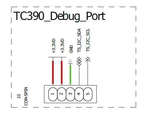
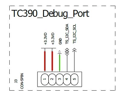
Schaltplan eines Debug-Ports
TC390_Debug_Port +3.3VD +3.3VD GND TS_I2C_SDA TS_I2C_SCL J3 CON-5PIN 1 2 3 4 5
in „Weitere Informationen zu Touch-Controller TC390“ · Mikrocontroller und Digitale Elektronik · · Schaltpläne
-
PDF
DS1267.pdf
: -40°C to +85°C L1 3 12 W0 W1 4 11 H0 PIN DESCRIPTIONS RST 5 10 L0 L0, L1 - Low End of Resistor H0, H1 - High End of Resistor CLK 6 9 COUT GND 7 8 DQ W0, W1 - Wiper Terminal of Resistor V B - Substrate Bias Voltage 14-Pin DIP (300-mil) S - Stacked Configuration Output OUT See Mech. Drawings Section RST - Serial Port Reset Input DQ - Serial Port Data Input CLK - Serial Port Clock Input VB 1 20 VCC NC 2 19 NC C OUT - Cascade
in „Poti mit Atmega8 ersetzen“ · Mikrocontroller und Digitale Elektronik ·
-
Datei
ThermometerSabine1.2.bas
Timer1 = Timer , Prescale = 1024 Enable Timer1 Enable Interrupts Dim Preload As Word Preload = &H48E5 'interrupt alle 6 Sek. Timer1 = Preload Config 1wire = Portc.3 ' DS18S20 on Port C.Pin3 Config Portd = Output 'Port D Ausgang für Motoren, Lampe "min" Config Portc.0 = Input 'PortC Eingang für Lichtschranken
in „Atmega8 Thermometer mit Schrittmotoranzeige“ · Projekte & Code ·
-
PDF
application-note-e2-ee03_v1_deutsch_03.pdf
5 Literaturhinweise: [1] Specification E2-interface; E + E Elektronik [2] E2_interface_EE03_Vxx; E + E Elektronik [3] E2_interface_EE07_Vxx; E + E Elektronik application-note-e2-ee03_d_v1_01.doc Seite 12/13 6 Anhang 6.1 Definitionen und Prototypen für das E2 Interfacemodul /***************************************************************************/ // SW-modul for E2 Interface // Target: SiLabs C8051F005 // Compiler: Keil C51 Version 5.1 // // created:
in „ATMEGA644 und E2-Interface (i2c) hilfe“ · Mikrocontroller und Digitale Elektronik ·
-
PDF
PCA8574-rev02.pdf
P0 4 PCA8574PW 13 INT AD0 6 PCA8574ATS 15 V SS P1 5 PCA8574APW 12 P7 AD1 7 14 P3 P2 6 11 P6 n.c. 8 13 n.c. 7 10 AD2 9 12 P2 P3 P5 VSS 8 9 P4 P0 10 11 P1 002aac941 002aac680 Fig 5. Pin configuration for TSSOP16 Fig 6. Pin configuration for SSOP20 6.2 Pin
in „NXP PCA8574 hat Phänomen mit 2 Adressen“ · Mikrocontroller und Digitale Elektronik ·
-
PDF
AVR-Tutorial.pdf
jeweils mit Drähten verbindet (nicht Vcc und GND miteinander!). Die Versorgungsspannung Vcc beträgt 5V und kann z.B. mit folgender Schaltung erzeugt werden: • IC1: 5V-Spannungsregler 7805 • C1: Elko 10µF (Polung beachten!) • C2,C3: 2x Kondensator 100nF (kein Elektrolyt) • D1: Diode 1N4001 An den Eingang
in „AVR-Tutorial als PDF bzw *.doc“ · Mikrocontroller und Digitale Elektronik ·
-
PDF
Mik-k01-k04-AVR_uc.pdf
handeln soll. + Hat das Bit n im Datenrichtungsregister Low-Pegel, so ist der entsprechende Pin als Eingang konfiguriert. Der Schalter S3 (Schließer) ist in diesem Fall offen und trennt PortXn von PinXn. Schalter S1 (Öffner) ist geschlossen und schaltet den Pull-Up-Widerstand an PinXn, falls S2
in „Warum komme ich beim Auswärten des ADC's nur bis 25% ?“ · Mikrocontroller und Digitale Elektronik ·
-
PDF
IO_subprocessor_draft.pdf
_read lda ios_r0 ;input = %xxxxyyyy, xxxx = input, yyyy = previous output method2_initialize lda #is_ddrd ;point alternate index to port d ddr register sta ios_aad lda #$c0 ;pin 6-7 = output, pin 0-5 = input sta ios_ar lda #is_portd ;point alternate index to port d output register
in „ATMEGA16 Revision & USART receive buffer“ · Mikrocontroller und Digitale Elektronik ·
-
Datei
stm32_ub_spi1.c
von SPI1 //-------------------------------------------------------------- SPI1_DEV_t SPI1DEV = { // PORT , PIN , Clock , Source {GPIOA,GPIO_Pin_5,RCC_AHB1Periph_GPIOA,GPIO_PinSource5}, // SCK an PA5 {GPIOA,GPIO_Pin_7,RCC_AHB1Periph_GPIOA,GPIO_PinSource7}, // MOSI an PA7 {GPIOA,GPIO_Pin_6,RCC_AHB1Periph_GPIOA
in „STM32F429 - kein Takt am SPI“ · Mikrocontroller und Digitale Elektronik ·
-
Datei
disp.c
, positive clock phase, msb first, SPI speed fosc/2 SPCR = (1<<SPE) | (1<<MSTR); SPSR = (1<<SPI2X); delay_ms(300); } */ void DISP_test() { SPI_PORT &= ~(1<<SPI_SCK); delay_ms(75); for(unsigned char i=0; i<=131; i++){ DISP_Plot(i,88,blue); } DISP_Box(5,5,25,25,green); DISP_Box(5,35,25,55,orange); DISP_Box(5,65,25,85,red); DISP_Box(100,5,125,25,green); DISP_Box(100,35,125,55,orange); DISP_Box(100,65,125,85,red); //(x1,y1,x2,y2,color) SPI_PORT |= (1<<SPI_SCK); delay_ms(75);//hier
in „Bausatz Add-on für AVR-NET-IO“ · Mikrocontroller und Digitale Elektronik ·
-
PDF
MPX5700.pdf
Stage #1 Shift Circuitry PIN NUMBERS 1 Vout 4 N/C Pins 4, 5, and 6 are no connects 2 GND 5 N/C GND 3 V S 6 N/C NOTE: Pins 4, 5, and 6 are internal device Figure 1. Fully Integrated Pressure Sensor Schematic connections. Do not
in „Druckschalter Kompressorsteuerung für Weller Entlötstation WDD81V mit MPX5700 Drucksensor 0-7bar“ · Projekte & Code ·
-
Datei
main.c
config BOREN = ON // Brown-out Reset (BOR) Detection Enable bit (BOR is enabled) #pragma config ALTI2C1 = ON // Alternate I2C pins for I2C1 (ASDA1/ASCK1 pins are selected as the I/O pins for I2C1) #pragma config ALTI2C2 = ON // Alternate I2C pins for I2C2 (ASDA2/ASCK2 pins are selected as the I/O pins
in „dsPIC33E Probleme mit ADC/DMA“ · Mikrocontroller und Digitale Elektronik ·
-
PDF
CP2103.pdf
: Pins can be left unconnected when not used. 8 Rev. 1.0 CP2103 D R R D D S S D D D T R R C 8 7 6 5 4 3 2 SGND 2 2 2 2 2 2 2 RI 1 21 NC GND 2 20 NC D+ 3 19 GPIO.0 CP2103 D- 4 18 GPIO.1 Top View VIO 5 17 GPIO.2 VDD 6 16 GPIO.3 SGND REGIN 7 15 NC 8 9 0 1 2 3 4 1 1 1 1 1 S T C D D C C B R N E E N N V P P U U S S Figure 2. QFN-28 Pinout Diagram (Top View) Rev. 1.0 9 CP2103 Figure 3. QFN-28 Package Drawing Table
in „Verständnisfrage: CP2103 USB-Uart Bridge“ · FPGA, VHDL & Co. ·
-
Datei
_9341uno.ino
//Technical support:goodtft@163.com // Breakout/Arduino UNO pin usage: // LCD Data Bit : 7 6 5 4 3 2 1 0 // Uno dig. pin : 7 6 5 4 3 2 9 8 // Uno port/pin : PD7 PD6 PD5 PD4 PD3 PD2 PB1 PB0 // Mega dig. pin: 29 28 27 26 25 24 23 22 #define LCD_RD A0 #define LCD_WR
in „2.8 TFT von egeloo“ · Mikrocontroller und Digitale Elektronik ·
-
Datei
lcd_routines.c
// Ansteuerung eines HD44780 kompatiblen LCD im 4-Bit-Interfacemodus // http://www.mikrocontroller.net/articles/HD44780 // http://www.mikrocontroller.net/articles/AVR-GCC-Tutorial/LCD-Ansteuerung // // Die Pinbelegung ist über defines in lcd-routines.h einstellbar #include <avr/io.h> #include "lcd_routines.h" #include <util/delay.h> //////////////////////////////////////////////////////////////////////////////// // Erzeugt einen Enable-Puls static void lcd_enable( void ) { LCD_PORT |= (1<<LCD_EN); // Enable auf 1 setzen _delay_us( LCD_ENABLE_US ); // kurze Pause LCD_PORT &= ~(1<<LCD_EN); // Enable auf
in „Zeilenadressen LCD 4x20 blau“ · Mikrocontroller und Digitale Elektronik ·
-
Datei
lcd_routines.c
// Ansteuerung eines HD44780 kompatiblen LCD im 4-Bit-Interfacemodus // http://www.mikrocontroller.net/articles/HD44780 // http://www.mikrocontroller.net/articles/AVR-GCC-Tutorial/LCD-Ansteuerung // // Die Pinbelegung ist über defines in lcd-routines.h einstellbar #include <avr/io.h> #include "lcd-routines.h" #include <util/delay.h> //////////////////////////////////////////////////////////////////////////////// // Erzeugt einen Enable-Puls static void lcd_enable( void ) { LCD_PORT |= (1<<LCD_EN); // Enable auf 1 setzen _delay_us( LCD_ENABLE_US ); // kurze Pause LCD_PORT &= ~(1<<LCD_EN); // Enable auf
in „attiny2313, LCD, 4-Bit, C, Einzelne Zeichen falsch“ · Mikrocontroller und Digitale Elektronik ·
-
Datei
LCD-Routines.c
// Ansteuerung eines HD44780 kompatiblen LCD im 4-Bit-Interfacemodus // http://www.mikrocontroller.net/articles/HD44780 // http://www.mikrocontroller.net/articles/AVR-GCC-Tutorial/LCD-Ansteuerung // // Die Pinbelegung ist über defines in lcd-routines.h einstellbar #include <avr/io.h> #include "lcd-routines.h" #include <util/delay.h> //////////////////////////////////////////////////////////////////////////////// // Erzeugt einen Enable-Puls static void lcd_enable( void ) { LCD_PORT |= (1<<LCD_EN); // Enable auf 1 setzen _delay_us( LCD_ENABLE_US ); // kurze Pause LCD_PORT &= ~(1<<LCD_EN); // Enable auf
in „attiny2313, LCD, 4-Bit, C, Einzelne Zeichen falsch“ · Mikrocontroller und Digitale Elektronik ·
-
Datei
lcd-routines.c
// Ansteuerung eines HD44780 kompatiblen LCD im 4-Bit-Interfacemodus // http://www.mikrocontroller.net/articles/HD44780 // http://www.mikrocontroller.net/articles/AVR-GCC-Tutorial/LCD-Ansteuerung // // Die Pinbelegung ist über defines in lcd-routines.h einstellbar #include <avr/io.h> #include "lcd-routines.h" #include <util/delay.h> //////////////////////////////////////////////////////////////////////////////// // Erzeugt einen Enable-Puls static void lcd_enable( void ) { LCD_PORT |= (1<<LCD_EN); // Enable auf 1 setzen _delay_us( LCD_ENABLE_US ); // kurze Pause LCD_PORT &= ~(1<<LCD_EN); // Enable auf
in „splc780d LCD Pollin“ · Mikrocontroller und Digitale Elektronik ·
-
Datei
lcd-routines.c
// Ansteuerung eines HD44780 kompatiblen LCD im 4-Bit-Interfacemodus // http://www.mikrocontroller.net/articles/HD44780 // http://www.mikrocontroller.net/articles/AVR-GCC-Tutorial/LCD-Ansteuerung // // Die Pinbelegung ist über defines in lcd-routines.h einstellbar #include <avr/io.h> #include "lcd-routines.h" #include <util/delay.h> //////////////////////////////////////////////////////////////////////////////// // Erzeugt einen Enable-Puls static void lcd_enable( void ) { LCD_PORT |= (1<<LCD_EN); // Enable auf 1 setzen _delay_us( LCD_ENABLE_US ); // kurze Pause LCD_PORT &= ~(1<<LCD_EN); // Enable auf
in „Atmega8 und LCD Display“ · Mikrocontroller und Digitale Elektronik ·
-
Datei
lcd-routines.c
// Ansteuerung eines HD44780 kompatiblen LCD im 4-Bit-Interfacemodus // http://www.mikrocontroller.net/articles/HD44780 // http://www.mikrocontroller.net/articles/AVR-GCC-Tutorial/LCD-Ansteuerung // // Die Pinbelegung ist über defines in lcd-routines.h einstellbar #include <avr/io.h> #include "lcd-routines.h" #include <util/delay.h> //////////////////////////////////////////////////////////////////////////////// // Erzeugt einen Enable-Puls static void lcd_enable( void ) { LCD_PORT |= (1<<LCD_EN); // Enable auf 1 setzen _delay_us( LCD_ENABLE_US ); // kurze Pause LCD_PORT &= ~(1<<LCD_EN); // Enable auf
in „A/D-Wandler-Test mit Analogwert-Anzeige auf LCD“ · Mikrocontroller und Digitale Elektronik ·
-
Datei
lcd-routines.c
// Ansteuerung eines HD44780 kompatiblen LCD im 4-Bit-Interfacemodus // http://www.mikrocontroller.net/articles/HD44780 // http://www.mikrocontroller.net/articles/AVR-GCC-Tutorial/LCD-Ansteuerung // // Die Pinbelegung ist über defines in lcd-routines.h einstellbar #include <avr/io.h> #include "lcd-routines.h" #include <util/delay.h> //////////////////////////////////////////////////////////////////////////////// // Erzeugt einen Enable-Puls static void lcd_enable( void ) { LCD_PORT |= (1<<LCD_EN); // Enable auf 1 setzen _delay_us( LCD_ENABLE_US ); // kurze Pause LCD_PORT &= ~(1<<LCD_EN); // Enable auf
in „Fehler bei "o" im LCD?“ · Mikrocontroller und Digitale Elektronik ·
-
Datei
lcd-routines.c
// Ansteuerung eines HD44780 kompatiblen LCD im 4-Bit-Interfacemodus // http://www.mikrocontroller.net/articles/HD44780 // http://www.mikrocontroller.net/articles/AVR-GCC-Tutorial/LCD-Ansteuerung // // Die Pinbelegung ist über defines in lcd-routines.h einstellbar #include <avr/io.h> #include "lcd-routines.h" #include <util/delay.h> //////////////////////////////////////////////////////////////////////////////// // Erzeugt einen Enable-Puls static void lcd_enable( void ) { LCD_PORT |= (1<<LCD_EN); // Enable auf 1 setzen _delay_us( LCD_ENABLE_US ); // kurze Pause LCD_PORT &= ~(1<<LCD_EN); // Enable auf
in „Zeitbasierte Aktionen“ · Mikrocontroller und Digitale Elektronik ·