alsa selbst zu installieren, scheint wohl in deren XBMC build integriert zu sein. Hab weder alsa-base noch alsa-utils installiert (wurde auch nicht automatisch installiert) und xbmc listet es trotzdem als ALSA device auf. Vielen dank! :)
18:29:58 BST 2014 armv6l GNU/Linux Update: Linux Internetradio 3.12.35+ #733 PREEMPT Tue Jan 6 21:03:44 GMT 2015 armv6l GNU/Linux Internetradio Programm läuft noch… aplay –l sagt **** Liste der Hardware-Ger▒te (PLAYBACK) **** Karte 0: ALSA [bcm2835 ALSA], Ger▒t 0: bcm2835 ALSA [bcm2835
Starting scheduler on PRO CPU. I (0) cpu_start: Starting scheduler on APP CPU. I (474) system_api: Base MAC address is not set I (484) system_api: read default base MAC address from EFUSE I (484) WIFI_STA MAC: 0x8c, 0xaa, 0xb5, 0x8b, 0x25, 0x50 I (494) main: Starting program I (534) main: Done nvs_flash_init
the scale on its side to disassemble and mount the display unit. Unfasten the Allen screws on the base plate and remove the base plate. Remove the fastening screws. 1–16 Remove the screws on the retainer plate. Then set the scale back upright. Remove the screws on the base (7). Lay the support arm along with the base and the display unit on a table. Remove the plugs from the long side of the scale (insert them in the holes on the short side). Loosely attach the display unit with the support arm and base to the long
PNP Transistoren in DFN1110D-3. • BAT32LS-Q und BAT42LS-Q Schottky-Dioden in DFN1006BD-2 • BAS21LS-Q Schaltdiode in DFN1006BD-2. • PDTA143/114/124/144EQB-Q - 50 V 100 mA PNP Resistor-Equipped Transistors (RET) in DFN1110D-3. • 2N7002KQB - 60 V N-Kanal Trench MOSFET und BSS84AKQB -
GPS-Rollover, siehe auch https://de.racelogic.support/01VBOX_Automotive/01Allgemeine_Informationen/Knowledge_Base/Was_ist_GPS-Rollover%3F 0. Beginn: 6. Jan 1980 1. Rollover: 21. Aug 1999 2. Rollover: 6. Apr 2019 3. Rollover: 20. Nov 2038 Der etrex H kam 2006/2007 auf den Markt, also haben
ohne Anzapfung (primär 220V), danach B80C3200/2200, 2,2mF und daran 3* TIP142 parallel, die Basen hart parallelgeschaltet, in jedem Emitterzweig 1,2Ω. Einer der insgesamt 2*3 Darlingtons war durchlegiert, trotz der nur 1,5A und "richtig fettem" Kühlkörper; der genaue Ausfallgrund blieb
von IXYS ist sauteuer. >die schaffen bei 75°C bis 10A bei 35V: @ Tc=75°C ja. Der R_thCS ist 0,21 °C/W für TO247 angegeben, mit Glimmscheibe dazwischen noch schlechter. D.h, es ist unmöglich unter realer Bedingung die Tc von 75°C zu halten bei 350W Verlustleitung. Realistisch wäre ca. 120W bei KK
das ist > auch bei c++ nicht anders. Du bezeichnest hier offentlichtlich struct sensor als den base-type (wird ja so ähnlich wie ein eingebettetes Basisklassenobjekt bei C++ verwendet). Dann brauchst aber keinen "up-cast" sondern einen "down-cast" von struct sensor* auf etwa struct audio_sensor_1*
.992f08af-eb2a-4a7b-90a4-cd77032caf05&pf_rd_p=992f08af-eb2a-4a7b-90a4-cd77032caf05&pf_rd_r=D8QH90VS1MGE73FQ21AY&pd_rd_wg=JGIcD&pd_rd_r=07f5d4cf-36c9-4db1-8a3c-872d9689291d&pd_rd_i=B000XZZQ6U&th=1 habe ich auf einen Holzstab montiert gehabt und diesen drehbar auf einen Stil drauf gesteckt. Somit hatte das
hochwertige Aluminiumlegierung" https://www.hornbach.de/shop/Balkonstaender-fuer-SAT-Antennen-Schwaiger-BAS5550011/4064857/artikel.html https://www.hornbach.de/shop/Alu-Wandhalter-250-mm-fuer-Satellitenantennen-Schwaiger-WAH25A001/7280729/artikel.html und drei weitere "Material Aluminium" wenigstens
www.elv.de/Universal-Thermostat-UT-200,-Komplettbausatz/x.aspx/cid_74/detail_10/detail2_22053/refid_GoogleBase - nur habe ich keine Idee wie ich das mit der Haltezeit (0 bis 10 Minuten) hinbekomen soll?!
ich den DS18S20 anfasse, aber ich werde nicht schlau daraus z.Z. leuchten bei Raumtemp von etwa 21°C follgende LED's B0, B1, B4, B5, B7 viele Grüße Rocco
Output voltage IO= 5 mA to 1 A, VI= 8.6 to 19 V 5.76 6 6.24 V VO Output voltage IO= 1 A, VI= 19 to 21 V,JT = 25°C 5.76 6 6.24 V VI= 8.6 to 25 V,OI = 500 mA, J = 25°C 9 60 mV VI= 9 to 13 V 11 60 mV ΔV O(1) Line regulation VI= 9 to 13 V, J = 25°C 3 30 mV VI= 8.3 to 21 V,JT = 25°C 9 60 mV IO = 5 mA to 1
Bei der Lernbetty hatte mich auch mal jemand gefragt, wozu denn die Auftrennung zwischen BettyBase und den BettyApps gut sein soll. Eben dazu, daß ein jedes separat gepflegt werden kann. Aber mit nem beim Linken einer einzigen Firmware mit eingebundenen RTOS (wie es deinen Vorstellungen enspricht
man natürlich auch machen, erinnert einen so ein bisschen an die alten DOS Zeiten, wie war das? INT21? ;-) W.S. schrieb im Beitrag #3392740: > Ich bin wirklich nicht dogmatisch, aber ich bevorzuge es, praktisch zu > denken und da kommt mir immer wieder die Frage hoch, _WOZU?_ und die hat > mir
LASER PROTECTION AT SEE FIGURE 6IN. * = 1% METAL FILM RESISTOR = 1N4148, UNLESS NOTED = LASER AN90 F21 Figure 21. Circuit Has Laser Anode Committed to Supply, Inherent Self-Enabled Operation. LT1635 Functions at 1.2V, Although Self-Enable Feature Holds Off Output Until Power Supply Exceeds 2V. Current
Ableben besonders gewürdigt wird. Wenn ich bedenke, wie lange das Unglück der Loveparade 2010 mit 21 Toten in den Medien präsent ist, mit Jahrestagen, Gedenksteinen usw. steht das in keinem Verhältnis zu der gleichen Anzahl Verkehrstote ca. alle 2 Tage in D. Ich finde es finde es auch immer seltsam
ihm passierte. Ob er auch künftig wieder Base-jumpen wolle, wurde er danach gefragt. Klar wolle er, war seine Antwort. Wenn der beim nächsten mal zerfetzt am Boden ankommt. Soll dann die Medien-Mitleidsmaschine auch für ihn trommeln? Oder sind
ik 0 1 . M K R121 5.5 A PAL BASE BAND D153 470 N Ai.c C 0 I D102 1k 0.6 SW B MAC BASE BAND B LN21RPH R165 A A o m GMA01 R134 Q101 0.1 47k R V .pRR GND DATA CLK EN VCC R138 0 C EXT VIDEO IN SW 0.7 5 11 FUNCTION TUNING UP I 50 16 l 15
waveformis error when recovery M the source setting to the factory settings and opensource output. 21. The signal wave does not move when adjust the time base M from the maximum value to the minimum value under the wait state. 22. The SPI data set will be error when the SPI data widthless M than 8 under
945+ICH7 3.0GHz DDR:400 Testing Software: HD Bench 3.4 Testing OS: Windows XP The value is various bases on the testing platform. 2.3.5 Data Retention ▯ 10years without requiring power support 2.3.6 Wear-leveling ▯ Dynamic Wear-Leveling for same level of Write/Erase Cycle 2.3.7 Bad Block Management ▯
pF Ceramicctrolytic C R8 — 2.0 k C17, C18 — Two 0.1 F, 100 V Ceramic each, (ATC 200/823 or C R R9, R21, R22, R23, R24 — 10 k equivalent) R R10 — 8.2 k D1, D2, D3, D4 — 1N4148 A R15, R16, R17, R18 — 2.7 Ohms B1, B2, B3, B4 — Ferrite Beadsivalent A R19, R20 — 10 Ohms/2.0 W Carbon L1, L2 — Two Fair-Rite
andere Menschen meine Worte sinnvoll interpretieren könnten): Ich hab kein Problem damit, dass die BAs, insofern sie akkreditiert sind, Bachelorabschlüsse vergeben dürfen, die denen von FH und Uni gleichgestellt sind. Nur dann sollte man in manchen Bundesländern seitens des Gesetzgebers auch endlich mal bereit dazu sein die BAs in die Hochschulgesetze einzubeziehen. Sie vergeben Hochschulabschlüsse, sie lehren auf Hochschulniveau - ja warum fallen sie dann nicht unter die Hochschulgesetze?! Hier war man nicht konsequent genug
PARAMETER CONDITIONS TYP. MAX. UNIT R th j-mb Thermal resistance junction to - - 0.9 K/W mounting base R Thermal resistance junction to in free air 60 - K/W th j-a ambient(TO220AB) R th j-a Thermal resistance junction to Minimum footprint, FR4 50 - K/W ambient(SOT404) board July 2000 1 Rev 1.000 Philips
PARAMETER CONDITIONS TYP. MAX. UNIT R th j-mb Thermal resistance junction to - - 0.9 K/W mounting base R Thermal resistance junction to in free air 60 - K/W th j-a ambient(TO220AB) R th j-a Thermal resistance junction to Minimum footprint, FR4 50 - K/W ambient(SOT404) board July 2000 1 Rev 1.000 Philips
mit BAT60JFILM Schottky C14 C16 C21 +++ C20 SOD323 1uF 100nF 10nF 1uF 6,3V TACL105M006R B B 5V zu 3,3V U2 LD3985M33R +3V3 1 VIN VOUT 5 D 3 INH N Y G B 2 4 C15 C17 C19 +++ C18 1uF 100nF 10nF 1uF 6,3V C TACL105M006R C D D Spannungsregler
mit BAT60JFILM Schottky C14 C16 C21 +++ C20 SOD323 1uF 100nF 10nF 1uF 6,3V TACL105M006R B B 5V zu 3,3V U2 LD3985M33R +3V3 1 VIN VOUT 5 D 3 INH N Y G B 2 4 C15 C17 C19 +++ C18 1uF 100nF 10nF 1uF 6,3V C TACL105M006R C D D Spannungsregler
Ursache dafür ist, dass die anonymisierten Antworten zentralisiert gesammelt werden. Diese Knowledge Base dient dann erstens zur Beantwortung weiterer Fragen und zweitens zur Weiterentwicklung der Produkte und der Applikationsliteratur. ### Trumpf TruPlasma – Plasmagenerator mit EtherCAT-Interface Am
Signalgeneratoren, die nun wie in der Abbildung gezeigt bis zu 40 GHz erreichen. 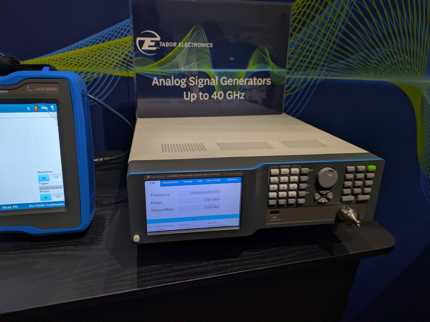 ### Rigol RSA7500 – neuer Spektrumanalysator in Prototypform Im Hause Rigol ist man – offensichtlich – in Sachen RF-Testgeräten auf den Geschmack gekommen. Mit dem Rigol RSA7500 zeigt man nun
APPROXIMATIONS BY CONTINUED FRACTIONS", SerdicaJ. Computing 1 (2007), 433{442 http://sci-gems.math.bas.bg:8080/jspui/bitstream/10525/355/1/sjc033-vol1-num4-2007.pdf
entspricht die Geschwindigkeit ziemlich genau einem i8080/Z80 mit 2.6 MHz. (Verglichen wurde FRACTAL.BAS unter MBASIC-80 mit den Zahlen von https://forum.classic-computing.de/forum/index.php?thread/22627-runcpm-speed-vergleich-auf-verschiedenen-plattformen/). Die Disk-Performance ist akzeptabel. Der
keine Antwort. Die erste Zeile von CPUTEST.HEX lautet: > :100100003E023CEA0030C30901F331FF2FCD4F21FD Das ist eindeutig an Adresse 0100h (: 10 *0100* 00...). Vielleicht mag DDT die Datei lieber: > DDT CPUTEST.HEX > ^C > SAVE 80 CPUTEST.COM Sollte aber einfacher sein, die originalen COM-Dateien
are defined as part of the port layer. THIS MUST BE THE SECOND MEMBER OF THE TCB STRUCT. */ ? BaseType_t xUsingStaticallyAllocatedStack; /* Set to pdTRUE if the stack is a statically allocated array, and pdFALSE if the stack is dynamically allocated. */ #endif 8 ListItem_t xGenericListItem
Vcom no load PWM output voltage V 0 - V PWM CC Feed back voltage V 0.55 0.6 0.65 DC/DC operating FB Base drive current I - - 1 V output =3.0V vs. 2.3V(External) PWMD PWM Base sink current I - - 1 VPWM output =0V vs. 0.7V(External) PWMS 表單編號: 版本: 本資料為統寶光電股份有限公司之智慧財產權及機密文件,非經本公司書面授權許可,不得透露或使用本資料,亦不得複印、複製或轉變成其
applications of PWM and larger diode capacitance, which can cause dimming with AIC 1896 are shown in Fig 21. One, significantswitching losses at the 1.4MHz as fig. 21(a), uses PWM signal to drive SHDN switching frequency of AIC1896. A Schottky diode pin directly for dimming control. The other, as fig. rated at 100mA to 200mA is sufficient for most 21(b), employs PWM signal going through a AIC1896 applications. resistor to drive FB pin. If tSHDN pin is used, the increase of duty cycle results in LED LED Current Control brightness enhancement. If the
Multiplication 4. Implementation Aryeh Eiderman <leib@eiderman.com> The given parameters are: v 0 base speed, 1. Cinematic basics v - slew speed, a - acceleration, F - timer frequency The linear acceleration (ramping) formulas are: and the calculated parameters are: S = v .t + a t / 2 [1], 0 . S - acceleration
outlined in its housing in Figure 1. The sensor element is a TM silicon diode, mounted on a plastic base, covered with a Teflon diffuser. The whole unit is placed on a base with a level control to ensure horizontality. In order to reduce undesirable effects of ambient temperature on measurement, the device
