-
 Bild
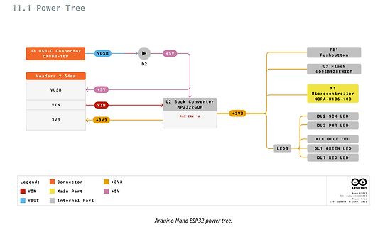
Blockschaltbild der Stromversorgung eines Arduino Nano ESP32
11.1 Power Tree J3 USB-C Connector CX98B-16P VUSB D2 +5V PB1 Pushbutton U3 Flash GD25B128EWIGR M1 Microcontroller NORA-W106-10B Headers 2.54mm VUSB VIN 3V3 +5V VIN U2 Buck Converter MP2322GQH MAX 20V 1A +3V3 +3V3 DL2 SCK LED DL3 PWR LED DL1 BLUE LED DL1 GREEN LED DL1 RED LED LEDS Legend:
in „Arduino Nano mit ESP32-Prozessor“ · Mikrocontroller und Digitale Elektronik · · Diagramme
-
PDF
170-04833-0-MB90549GPF.pdf
voltage VO V SS 0.3 V SS+ 6.0 V *2 Clamp Current ICLAMP 2.0 2.0 mA Max. overall Clamp Current ICLAMP 20.0 20.0 mA “L” level max. output current IL 15 mA *3 “L” level avg. output current OLAV 4 mA *4 “L” level max. overall output current IOL 100 mA “L” level avg. overall output current ILAV 50 mA *5 “H” level max. output current OH 15 mA *3 “H” level avg. output current OHAV 4 mA *4 “H” level max. overall output current IOH 100 mA “H” level avg. overall output current IHAV 50 mA *5 500 mW Flash device Power
in „16Bit PIC von Fujitsu .. hat jemand Informationen?“ · Mikrocontroller und Digitale Elektronik ·
-
Datei
Programm.txt
){}; //Wartet eine kurze Zeit //Aktiviren des SPI - Bus, Clock = Idel LOW //SPI Clock teilen durch 128 SPCR = (1<<SPE)|(1<<MSTR)|(1<<SPR0)|(1<<SPR1); //Enable SPI, SPI in Master Mode SPSR = (0<<SPI2X); //SPRO,SPR1=1 SPIX2=0 fosc/128 //Initialisiere MMC/SD-Karte in den SPI-Mode for (a = 0; a < 0x0f; a
in „ATMEGA8 -- SD/MMC Karte“ · Mikrocontroller und Digitale Elektronik ·
-
PDF
Funktionsbeschreibung.pdf
ist das Richtungsflag. 1 => Positive Bewegung (vom Nullpunkt weg). Alle übrigen Kombinationen (100-128 und 228-256) sind verboten.(reserviert für den Gebrauch als Sonderbefehle) ;************************************************** ; Start ; Name: COUNTERUPDATE ; ; Funktion: Aktualisiert den Zaehlerstand
in „[V] 2-fach ISEL Lineareinheit 300cm mit Zahnriemenantrieb Schrittmotor und Steuerung“ · Markt ·
-
Datei
Xorg.0.log.txt
v_sync: 1201 v_sync_end 1204 v_blanking: 1250 v_border: 0 [ 20.621] (II) SIS(0): Ranges: V min: 51 V max: 75 Hz, H min: 30 H max: 82 kHz, PixClock max 175 MHz [ 20.621] (II) SIS(0): Monitor name: P20-2 [ 20.621] (II) SIS(0): Serial No: YEMD033962 [ 20.621] (II) SIS(0): EDID (in hex): [ 20.621] (II) SIS
in „Notebook mit externem Monitor unter Ubuntu 12.04 LTS (32-bit) - Problem mit Auflösung“ · PC Hard- und Software ·
-
Datei
mmc.c
MMC_Direction_REG |= (1<<SPI_SS); // chip select auf output // hardware spi: bus clock = idle low, spi clock / 128 , spi master mode SPCR = (1<<SPE)|(1<<MSTR)|(1<<SPR0)|(1<<SPR1); MMC_Write |= (1<<SPI_SS); // chip selet auf high, karte anwaehlen } #if (MMC_MAX_SPEED==TRUE) // ***************************************************************************** static void spi_maxSpeed(){ //SPI Bus auf max Geschwindigkeit SPCR &= ~((1<<SPR0) | (1<<SPR1)); SPSR |= (1<<SPI2X); } #endif // ***************************************************************************** static void
in „MMC SD library FAT16 FAT32 read write“ · Projekte & Code ·
-
Datei
mmc.c
MMC_Direction_REG |= (1<<SPI_SS); // chip select auf output // hardware spi: bus clock = idle low, spi clock / 128 , spi master mode SPCR = (1<<SPE)|(1<<MSTR)|(1<<SPR0)|(1<<SPR1); MMC_Write |= (1<<SPI_SS); // chip selet auf high, karte anwaehlen } #if (MMC_MAX_SPEED==TRUE) // ***************************************************************************** static void spi_maxSpeed(){ //SPI Bus auf max Geschwindigkeit SPCR &= ~((1<<SPR0) | (1<<SPR1)); SPSR |= (1<<SPI2X); } #endif // ***************************************************************************** static void
in „SD-Card - SPI: kleine Fragen“ · Mikrocontroller und Digitale Elektronik ·
-
 Bild
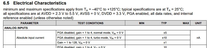
Ausschnitt einer Tabelle der elektrischen Eigenschaften
data rates, and internal reference enabled (unless otherwise noted) PARAMETER TEST CONDITIONS MIN TYP MAX UNIT ANALOG INPUTS PGA disabled, gain = 1 to 4, normal mode, VIN = 0 V ±5 nA PGA disabled, gain = 1 to 4, turbo mode, VIN = 0 V ±10 nA Gain = 1 to 128, VIN = 0 V ±1 PGA disabled, gain = 1 to 4, VIN
in „Ausmessen eines Thermopiles“ · Analoge Elektronik und Schaltungstechnik · · Screenshots
-
 Bild
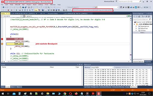
Microchip Studio Code Editor und Memory Ansicht
C_N1-ATMEGA128P_P40-M1_(324P20U) (Debugging) - Microchip Studio main.c //max7219_0_decode_mode(0xf); // if == Code B decode for digits 1-4, No decode for digits 5-8 while(1) { led1_ein; _delay_ms(150); led1_aus; _
in „welcher Debugger für 8bit Controller (AVR etc.) ?“ · Mikrocontroller und Digitale Elektronik · · Screenshots
-
Datei
page.html
title>WebSocket demo</title> </head> <body> <br>mySlider1: <input id="slider1" type="range" min="0" max="255" step="1" oninput="slider1();" value="128"> <p id="sliderValue1"> none </p> <script> var users = document.querySelector('users'), websocket = new WebSocket("ws://127.0.0.1:6789/"); function slider1
in „HTML Gui mit Slidern und Buttons“ · Softwareentwicklung ·
-
PDF
RV-3032-C7_App-Manual-rev1.3.pdf
. TEMP = 384/16 = 24°C 3. ∆T = Ttarget - TEMP = 26°C - 24°C = +2°C 4. TREF = 3059d 5. TREF = (3059/128 - 0.5)°C = 23.3984375°C 6. New TREF = TREF + ∆T = 23.3984375 °C + 2°C = 25.3984375°C 7. New TREF = (new TREF in °C + 0.5°C) × 128/°C = (25.3984375°C + 0.5°C) × 128/°C = 3315d 8. New TREF = 3315d May
in „ATtiny85 + Uhrenquarz mit 10 pF CL: Kondensatoren“ · Analoge Elektronik und Schaltungstechnik ·
-
Datei
decoder11n.ino
tone) * 1 or 2 or 3 or 4 etc // // init is 8928/558 = 16 *4 = 64 samples // // try to take n = 96 or 128 ;o) // // 48 : bandwidth around 186 hz f=496 Hz // // 64 : bandwidth around 140 hz f=558 Hz // // 96 : bandwidth around 94 hz f=744 Hz // // 128 : bandwidth around 70 hz f=992 Hz // // BUT remember
-
PDF
datasheet.pdf
1 0 1 : 8 1 : 4 0 1 1 1 : 16 1 : 8 2¡X0 PS2¡X 0 1 0 0 1 : 32 1 : 16 1 0 1 1 : 64 1 : 32 1 1 0 1 : 128 1 : 64 1 1 1 1 : 256 1 : 128 Prescaler assignment bit : 3 PSC 0 ¡XRTCC 1 ¡X Watchdog Timer RTCC signal Edge : 4 TCE 0 ¡X Increment on low-to-high transition on RTCC pin 1 ¡X Increment on high-to-low
-
Datei
log.txt
129,V2:0,V3:0] 2010-11-04 07:27:45 - 1762 - hap-scheduler - Info - destination 106 shutter-device 80 max-driving-time 125 2010-11-04 07:27:45 - 1762 - hap-scheduler - Info - [47%] [ACK] config HAP vlan 0 source 106 destination 238 abstract-device 80 property 128 value0 125 value1 0 [C:133,V:0,S:106,D:238
-
PDF
XPLAIN_Shematic.pdf
BK-G Jumper cap for 2.54mm pinheader SNT-100-BK-G SAMTEC SMD RF inductor 0402. Z=220Ohm (@100MHz), Max R(dc)=0.80Ohm, 2 L100, L200 BLM15BB221SN1 Max current=200mA BLM15BB221SN1 Murata PCBA identification label PP Top 1 LBL1 White Gloss Label PCBA Xplain PCB, 4-layer, size 54mm x 1 PCB1 A08-0551 85mm
in „Xplain: Schaltplan gesucht“ · Mikrocontroller und Digitale Elektronik ·
-
PDF
Futro_S700_fuer_Freifunk_nutzen.pdf
verschlüsselt werden. Genau die richtige Aufgabe für diesen Mini-Rechner. Benötigt wenig Watt (10-max. 20 Watt je nach Last), also ca. soviel wie zwei oder drei Router. Ausstattung Zusätzliche Netwerkkarten gibt es zu kaufen. Für intern oder als USB Interface, jedoch liegen hier keine Erfahrungen vor
-
PDF
ds-mb86r01-jade-rev1-4.pdf
Max. resolution is 1024 × 768 Max. 6 layered display Max. 2 screen output • Digital video capture function BT.601, BT.656, and RGB666 Max. 2 inputs • Geometry engine (MB86296 compatible display list is
in „Bild im Bild in der Instumententafel Range Rover“ · Mikrocontroller und Digitale Elektronik ·
-
PDF
SMCI33_Technisches_Handbuch_V2-1_de.pdf
Technische Daten 6 Technische Daten Elektrische Anschlüsse Betriebsspannung U b DC 24 V bis 48 V ±4% max. Phasenstrom einstellbar bis max. 3 A/Phase Dauerstrom 2 A/Phase Stromabsenkung einstellbar 0 bis 80% vom Phasenstrom Schnittstellen • SMCI33-1: USB-Standard • SMCI33-2 RS-485 (4-Draht) 19200 Baud (
in „Motorsteuerung von Nanotec in Betrieb nehmen“ · Mechanik, Gehäuse, Werkzeug ·
-
PDF
SMCI33_Technisches_Handbuch_V2-1_de.pdf
Technische Daten 6 Technische Daten Elektrische Anschlüsse Betriebsspannung U b DC 24 V bis 48 V ±4% max. Phasenstrom einstellbar bis max. 3 A/Phase Dauerstrom 2 A/Phase Stromabsenkung einstellbar 0 bis 80% vom Phasenstrom Schnittstellen • SMCI33-1: USB-Standard • SMCI33-2 RS-485 (4-Draht) 19200 Baud (
in „schrittmotorsteuerung smci33-2 von nanotec mit mikrocontroller steuern“ · Mikrocontroller und Digitale Elektronik ·
-
PDF
D120984D-1.pdf
condition, the module may be permanently destroyed. Note 2: VR Conditions: Zener Diode 20mA Note 3: 90% RH Max. (Max wet temp. is 60℃) Maximum wet-bulb temperature is at 60℃ or less. And No condensation (no drops of dew) +60℃ , 90%RH (℃ ) Note 4: In case of temperature below 0℃,the response time of liquid crystal
in „Bedarf an eigenbau STM32F429 Evaluation Board ?“ · Mikrocontroller und Digitale Elektronik ·
-
PDF
ATMega_48_88_168.pdf
CAL6..0 by 1 will give a frequency increment of less than 2% in the frequency range 7.3 - 8.1 MHz. 128 kHz Internal The 128 kHz internal Oscillator is a low power Oscillator providing a clock of 128 kHz. Oscillator The frequency is nominal at 3V and 25°C. This clock may be select as the system clock
in „I2C/TWI TWBR > 10 warum?“ · Mikrocontroller und Digitale Elektronik ·
-
Datei
Keyboard-Descriptor.txt
n> wMaxPacketSize: 0xae39<\r><\n> bInterval: 0xfb<\r><\n> <\r><\n> Endpoint Descriptor 128<\r><\n> bLength: 0xd5<\r><\n> bDescriptorType: 0x03<\r><\n> bEndpointAddress: 0x1e<\r><\n> bmAttributes: 0x2b<\r><\
in „USB-Host LPC1769“ · Mikrocontroller und Digitale Elektronik ·
-
 Bild
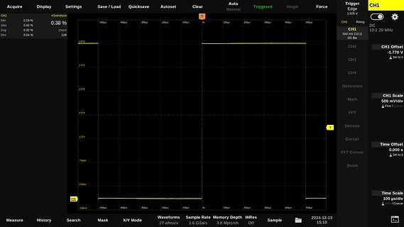
Oszilloskop-Screenshot einer Rechteckspannung
Settings Save / Load Quicksave Autoset Clear Auto Normal Triggered Single Force CH1 +Overshoot Min 0.24% Max 0.42% Avg 0.32% Dev 0.04% 128 Trigger Edge 1.505 V CH1 Rising DC 10:1 20 MHz CH1 500 mV (10:1) DC BW CH2 CH3 CH4 Reference CH1 Scale 500 mV/div Fine / Coarse CH2 -1.770 V Set to 0 CH3 CH4 FFT Decode
in „DSO Batronix Magnova? Erfahrungen?“ · Mechanik, Gehäuse, Werkzeug · · Oszi-Bilder
-
PDF
s1d13700.pdf
7-2 Generic Bus Direct/Indirect Interface with WAIT# Timing 3.3 Volt 5.0 Volt Symbol Parameter Min Max Min Max Units t1 CS# setup time 5 ⎯ 5 ⎯ ns t2 AB[15:0] setup time 5 ⎯ 5 ⎯ ns t3 WR#, RD# falling edge to WAIT# driven low 2 15 2 15 ns t4 DB[7:0] setup time to WR# rising edge (write cycle) Note 2 ⎯
in „LPC2140 an S1D13700 Display driver“ · Mikrocontroller und Digitale Elektronik ·
-
PDF
s1d13700.pdf
7-2 Generic Bus Direct/Indirect Interface with WAIT# Timing 3.3 Volt 5.0 Volt Symbol Parameter Min Max Min Max Units t1 CS# setup time 5 ⎯ 5 ⎯ ns t2 AB[15:0] setup time 5 ⎯ 5 ⎯ ns t3 WR#, RD# falling edge to WAIT# driven low 2 15 2 15 ns t4 DB[7:0] setup time to WR# rising edge (write cycle) Note 2 ⎯
in „[V] 8 LCDs 320x240 s/w, 6 Zoll, Touch, inkl Controller“ · Markt ·
-
PDF
s1d13700.pdf
7-2 Generic Bus Direct/Indirect Interface with WAIT# Timing 3.3 Volt 5.0 Volt Symbol Parameter Min Max Min Max Units t1 CS# setup time 5 ⎯ 5 ⎯ ns t2 AB[15:0] setup time 5 ⎯ 5 ⎯ ns t3 WR#, RD# falling edge to WAIT# driven low 2 15 2 15 ns t4 DB[7:0] setup time to WR# rising edge (write cycle) Note 2 ⎯
in „Erste GLCD (Touch) -Schaltung“ · Mikrocontroller und Digitale Elektronik ·
-
PDF
s1d13700.pdf
7-2 Generic Bus Direct/Indirect Interface with WAIT# Timing 3.3 Volt 5.0 Volt Symbol Parameter Min Max Min Max Units t1 CS# setup time 5 ⎯ 5 ⎯ ns t2 AB[15:0] setup time 5 ⎯ 5 ⎯ ns t3 WR#, RD# falling edge to WAIT# driven low 2 15 2 15 ns t4 DB[7:0] setup time to WR# rising edge (write cycle) Note 2 ⎯
in „[v] LCDs 320x240 s/w, 6 Zoll, Touch, inkl Controller“ · Markt ·
-
PDF
s1d13700_320-240_display.pdf
7-2 Generic Bus Direct/Indirect Interface with WAIT# Timing 3.3 Volt 5.0 Volt Symbol Parameter Min Max Min Max Units t1 CS# setup time 5 ⎯ 5 ⎯ ns t2 AB[15:0] setup time 5 ⎯ 5 ⎯ ns t3 WR#, RD# falling edge to WAIT# driven low 2 15 2 15 ns t4 DB[7:0] setup time to WR# rising edge (write cycle) Note 2 ⎯
in „Anstuerung eines Grafik LCDs. Fragen zu Display und Controller“ · Mikrocontroller und Digitale Elektronik ·
-
PDF
sst_flash_39vf010_1Mbit.pdf
µA CE#=V IHC, DD=VDD Max LI Input Leakage Current 1 µA VINGND to V DD, DD =VDD Max I Output Leakage Current 10 µA V =GND to V , V =V Max LO OUT DD DD DD VIL Input Low Voltage 0.8 V VDD=V DDMin VIH Input High Voltage 0.7VDD
in „Flashspeicher aus USB-Stick mit ATMega8 nutzen“ · Mikrocontroller und Digitale Elektronik ·
-
PDF
en.DM00047230.pdf
Table 5. Value range for IEEE.754 number formats Sign Exponent Fraction Number 0 0 0 +0 1 0 0 -0 0 Max 0 +∞ 1 Max 0 -∞ [0, 1] Max !=0 & MSB=1 QNaN [0, 1] Max !=0 & MSB=0 SNaN [0, 1] 0 !=0 Denormalized Number [0, 1] [1, Max-1] [0, Max] Normalized Number 10/31 DocID022737 Rev 2 AN4044 IEEE standard for
in „Rechenzeitoptimierung STM32F4“ · Mikrocontroller und Digitale Elektronik ·
-
PDF
Si_4322.pdf
V o T st Storage temperature -55 125 C o T ld Lead temperature (soldering, max 10 s) 260 C Recommended Operating Range ELECTRICALSPECIFICATION (Min/max values are valid over the whole recommended operating range, typ conditions: T = 27 C; V = 2.7 V) op dd DC Characteristics Symbol
in „RFM01 NIRQ immer high“ · Mikrocontroller und Digitale Elektronik ·
-
PDF
ATmega48PA-ATmega88PA-ATmega168PA_Datasheet.pdf
programming the CKSEL fuses to “11” as shown in Table 9-13. Table 9-13. 128kHz Internal Oscillator Operating Modes Nominal Frequency (1) CKSEL3...0 128kHz 0011 Note: 1. Note that the 128kHz oscillator is a very low power clock source, and is not designed for high accuracy.
in „Probleme mit Int Capt ISR ATmega48PA“ · Mikrocontroller und Digitale Elektronik ·
-
Datei
hardware_t.cpp
Trigger_Pos_CH4-GRID_HEIGHT/2)/ScaleFactor[Selected_Voltage_CH4][GainIdx])+ADC_ZERO; break; } Signal::CalcMinMax(start,stop,1,pSignal,&min,&max); if (((oldMin<tvalue) && (max>tvalue)) || ((oldMax>tvalue) && (min<tvalue)) || (min<tvalue && max>tvalue)) { //triggervalue crossed--> enable normal-mode ctrl_reg &=
in „Wittig(welec) DSO W20xxA Open Source Firmware (Teil4)“ · Mikrocontroller und Digitale Elektronik ·
-
Datei
ApplComm.c
*********************************************************************************/ #define APPLCOM_MAX_LOG_CHANNELS 6 tBswDp_Channelindex ApplComm_LogChannelList[APPLCOM_MAX_LOG_CHANNELS]; void ApplComm_Init(void) { u08 i; for (i=0; i<APPLCOM_MAX_LOG_CHANNELS; i++) { ApplComm_LogChannelList[i] = 0xFF
-
PDF
d16311gc.pdf
digit) • Key scanning (12 4 matrices) • Dimming circuit (eight steps) • High-voltage output (VDD 35 V max). • LED ports (5 chs., 20 mA max). • General-purpose input port (4 bits) • No external resistor necessary for driver outputs (P-ch open-drain + pull-down resistor output) • Serial interface (CLK, STB
in „Daten vom Vfd Controller Abfangen“ · Mikrocontroller und Digitale Elektronik ·
-
PDF
74ABT573A_philips_Latch_3_state.pdf
CHARACTERISTICS LIMITS T = –40⋅C SYMBOL PARAMETER TEST CONDITIONS Tamb = +25⋅C ato +85⋅C UNIT Min Typ Max Min Max V IK Input clamp voltage VCC = 4.5V; IK= –18mA –0.9 –1.2 –1.2 V VCC = 4.5V; OH = –3mA; V I V IL V IH 2.5 2.9 2.5 V VOH High-level output voltage VCC = 5.0V; OH = –3mA; V I V IL V IH 3.0 3.4
in „Latch, aber welches?“ · Mikrocontroller und Digitale Elektronik ·
-
PDF
Powertip_PE12864LRF-042-H-Q.pdf
) Page3 SAMPLE Ver.01 SPEC Edi.003 1. SPECIFICATIONS 1.1 Features Item Standard Value Display Type 128*64 Dots LCD Type FSTN, Positive,Transflective, Extended Temperature Driver Condition LCD Module:1/65 Duty,1/9 Bias Viewing Direction 6 O’clock Backlight Yellow-Green LED B/L Weight 29.4 g Interface
in „POWERTIP LCD PE12864-003 Anschlussbelegung gesucht“ · Mikrocontroller und Digitale Elektronik ·
-
Datei
page3.html
title>WebSocket demo</title> </head> <body> <br>mySlider: <input id="slider3" type="range" min="0" max="255" step="1" oninput="slider3();" value="128"> <div class="state"> <span class="users">?</span> online </div> <script> var users = document.querySelector('users'), websocket = new WebSocket("ws://
in „HTML Gui mit Slidern und Buttons“ · Softwareentwicklung ·
-
PDF
display.PDF
TG12864B-03 ■ Series ■ Electrical Characteristics Standard value Display Format 128 X 64 DOTS ITEM Symbol Condition UNIT Min. Typ. Max. Drive Method 1/64 Duty ; 1/9 Bias Supply Voltage For Logic V DD SS -- 4.5 5.0 5.5 V Supply Voltage For LCD VDDV 0 -- -- 9.0 -- V LCD Type STN Blue
in „bin Anfänger will Atmega16 Flashen“ · Mikrocontroller und Digitale Elektronik ·
-
PDF
D120424D.pdf
TG12864B-03 ■ Series ■ Electrical Characteristics Standard value Display Format 128 X 64 DOTS ITEM Symbol Condition UNIT Min. Typ. Max. Drive Method 1/64 Duty ; 1/9 Bias Supply Voltage For Logic V DD SS -- 4.5 5.0 5.5 V Supply Voltage For LCD VDDV 0 -- -- 9.0 -- V LCD Type STN Blue
in „LCD-Display dateblatt“ · Mikrocontroller und Digitale Elektronik ·
-
PDF
atmega2560_2561.pdf
power 6 CK 14CK + 65 ms(1) 10 Reserved 11 Note: 1. The device is shipped with this option selected. 128 kHz Internal The 128 kHz internal Oscillator is a low power Oscillator providing a clock of 128 kHz. Oscillator The frequency is nominal at 3V and 25°C. This clock may be select as the system clock
in „Ethernet Buchse“ · Mikrocontroller und Digitale Elektronik ·
-
PDF
TMC262_datasheet.pdf
and DIR Interface Timing AC-Characteristics clock period is CLK Parameter Symbol Conditions Min Typ Max Unit Step frequency (at maximum fSTEP DEDGE=0 ½ fCLK microstep resolution) DEDGE=1 ¼ fCLK Fullstep frequency FS fCLK12 max(t , STEP input low time SL t +20)TSD ns CLK STEP input high time SH max(FILTSD
in „Wärmeentwicklung Mosfet“ · Mikrocontroller und Digitale Elektronik ·
-
PDF
B101EW05_V0.pdf
points average) (Note: ILED is LED current) 297 min. (5 points average) Luminance Uniformity 1.25 max. (5 points) Contrast Ratio 1500 typ, 1000 min. Response Time [ms] 25 typ / 35 Max [Volt] Nominal Input Voltage VDD +3.3 typ. Power Consumption [Watt] 3.4 max. (Include Logic and Blu power) Weight [Grams
in „Handydummy (Attrappe)mit richtigem Display 10Zoll - u.a.Motorola Xoom“ · Mikrocontroller und Digitale Elektronik ·
-
PDF
B156XW03_V.2.pdf
current)) [cd/m ] 200 typ. (5 points average) 170 min. (5 points average) Luminance Uniformity 1.25 max. (5 points) Contrast Ratio 500 typ Response Time [ms] 8 typ / 15 Max Nominal Input Voltage VDD [Volt] +3.3 typ. Power Consumption [Watt] 5.4 max. (Include Logic and BLU power) Weight [Grams] 425 max
in „Pollin LVDS-Board an B156XW03 Display“ · Mikrocontroller und Digitale Elektronik ·
-
PDF
MX25L12835E__3V__128Mb__v1.3.pdf
block (64K-byte per block); 80s(typ.) / chip • Low Power Consumption - Low active read current: 19mA(max.) at 104MHz, 15mA(max.) at 66MHz and 10mA(max.) at 33MHz - Low active programming current: 25mA (max.) - Low active erase current: 25mA (max.) - Low standby current: 100uA (max.) - Deep power down current
in „FLASH Memory Chip im Lenovo X200 von 8 MB auf 16 MB vergroessern“ · PC Hard- und Software ·
-
 Bild
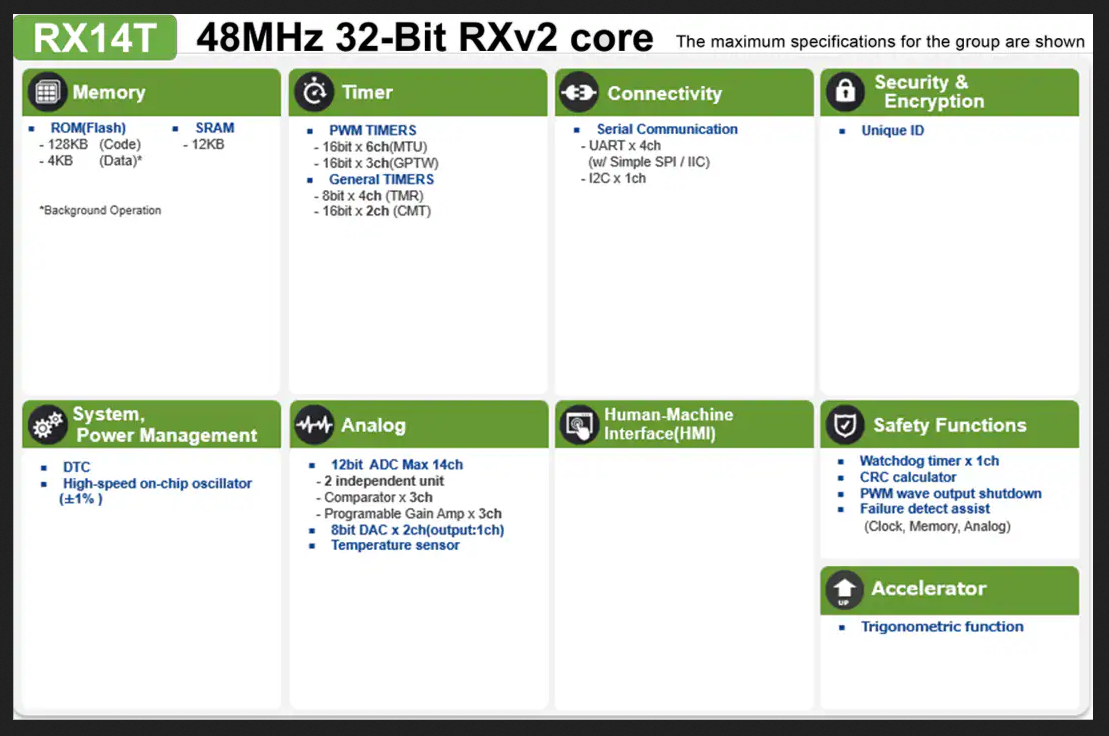
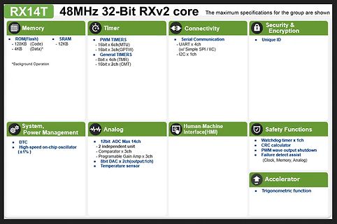
Spezifikationsübersicht RX14T 48MHz 32-Bit RXv2 Core
RX14T 48MHz 32-Bit RXv2 core Memory ROM(Flash) - 128KB (Code) - 4KB (Data)* SRAM - 12KB Timer PWM TIMERS - 16bit x 6ch(MTU) - 16bit x 3ch(GPTW) General TIMERS - 8bit x 4ch (TMR) - 16bit x 2ch (CMT) Connectivity Serial Communication - UART x 4ch (w/ Simple
in „Neue Bauteile: Hochgeschwindigkeitsfunk, Löttechnik und die Rückkehr der QWERTZ-Tastatur“ · Mikrocontroller und Digitale Elektronik · · Screenshots
-
PDF
TG12864B-05.pdf
TG12864B-05 ■ Series ■ Electrical Characteristics Standard value Display Format 128 X 64 DOTS ITEM Symbol Condition UNIT Min. Typ. Max. Drive Method 1/64 Duty ; 1/9 Bias Supply Voltage For Logic V DD SS -- 4.5 5.0 5.5 V Supply Voltage For LCD VDDV 0 -- -- 9.0 -- V LCD Type STN/Transflective
in „KS0108 Pinbelegung Versorgungsspannung“ · Analoge Elektronik und Schaltungstechnik ·
-
PDF
TG12864b.pdf
TG12864B-05 ■ Series ■ Electrical Characteristics Standard value Display Format 128 X 64 DOTS ITEM Symbol Condition UNIT Min. Typ. Max. Drive Method 1/64 Duty ; 1/9 Bias Supply Voltage For Logic V DD SS -- 4.5 5.0 5.5 V Supply Voltage For LCD VDDV 0 -- -- 9.0 -- V LCD Type STN/Transflective
in „GLCD von Pollin (LCD-Modul TG12864B-05)“ · Mikrocontroller und Digitale Elektronik ·
-
PDF
pollin_lcd_128_64.pdf
TG12864B-05 ■ Series ■ Electrical Characteristics Standard value Display Format 128 X 64 DOTS ITEM Symbol Condition UNIT Min. Typ. Max. Drive Method 1/64 Duty ; 1/9 Bias Supply Voltage For Logic V DD SS -- 4.5 5.0 5.5 V Supply Voltage For LCD VDDV 0 -- -- 9.0 -- V LCD Type STN/Transflective
in „Problem mit Displaydatenblatt“ · Mikrocontroller und Digitale Elektronik ·