-
Datei
lcd-routines.c
// Ansteuerung eines HD44780 kompatiblen LCD im 4-Bit-Interfacemodus // http://www.mikrocontroller.net/articles/HD44780 // http://www.mikrocontroller.net/articles/AVR-GCC-Tutorial/LCD-Ansteuerung // // Die Pinbelegung ist über defines in lcd-routines.h einstellbar #include <avr/io.h> #include "lcd-routines.h" #include <util/delay.h> //////////////////////////////////////////////////////////////////////////////// // Erzeugt einen Enable-Puls static void lcd_enable( void ) { LCD_PORT |= (1<<LCD_EN); // Enable auf 1 setzen _delay_us( LCD_ENABLE_US ); // kurze Pause LCD_PORT &= ~(1<<LCD_EN); // Enable auf
in „AVR GCC LCD Turorial mit OLED EA W082-XLG geht nicht“ · Mikrocontroller und Digitale Elektronik ·
-
Datei
lcd-routine.c
// Ansteuerung eines HD44780 kompatiblen LCD im 4-Bit-Interfacemodus // http://www.mikrocontroller.net/articles/HD44780 // http://www.mikrocontroller.net/articles/AVR-GCC-Tutorial/LCD-Ansteuerung // // Die Pinbelegung ist über defines in lcd-routines.h einstellbar #include <avr/io.h> #include "lcd-routine.h" #include <util/delay.h> //////////////////////////////////////////////////////////////////////////////// // Erzeugt einen Enable-Puls static void lcd_enable( void ) { LCD_PORT |= (1<<LCD_EN); // Enable auf 1 setzen _delay_us( LCD_ENABLE_US ); // kurze Pause LCD_PORT &= ~(1<<LCD_EN); // Enable auf
in „Atmega 16MHz delay-Funktion“ · Mikrocontroller und Digitale Elektronik ·
-
Datei
lcd-routines.c
// Ansteuerung eines HD44780 kompatiblen LCD im 4-Bit-Interfacemodus // http://www.mikrocontroller.net/articles/HD44780 // http://www.mikrocontroller.net/articles/AVR-GCC-Tutorial/LCD-Ansteuerung // // Die Pinbelegung ist über defines in lcd-routines.h einstellbar #include <avr/io.h> #include "lcd-routines.h" #include <util/delay.h> //////////////////////////////////////////////////////////////////////////////// // Erzeugt einen Enable-Puls static void lcd_enable( void ) { LCD_PORT |= (1<<LCD_EN); // Enable auf 1 setzen _delay_us( LCD_ENABLE_US ); // kurze Pause LCD_PORT &= ~(1<<LCD_EN); // Enable auf
in „displaytech 204A gibt nur <- und 0 aus.“ · Mikrocontroller und Digitale Elektronik ·
-
Datei
lcd-routines.c
// // Die Pinbelegung ist über defines in lcd-routines.h einstellbar #include <avr/io.h> #include "lcd-routines.h" #include <util/delay.h> //////////////////////////////////////////////////////////////////////////////// // Erzeugt einen Enable-Puls static void lcd_enable( void ) { LCD_PORT |= (1<<LCD_EN); // Enable auf 1 setzen _delay_us( LCD_ENABLE_US ); // kurze Pause LCD_PORT &= ~(1<<LCD_EN); // Enable auf 0 setzen } //////////////////////////////////////////////////////////////////////////////// // Sendet eine 4-bit Ausgabeoperation an das LCD static void lcd_out( uint8_t data ) { data &= 0xF0
in „mega8 Flash Verwirrung“ · Mikrocontroller und Digitale Elektronik ·
-
Datei
lcd-routines.c
// Ansteuerung eines HD44780 kompatiblen LCD im 4-Bit-Interfacemodus // http://www.mikrocontroller.net/articles/HD44780 // http://www.mikrocontroller.net/articles/AVR-GCC-Tutorial/LCD-Ansteuerung // // Die Pinbelegung ist über defines in lcd-routines.h einstellbar #include <avr/io.h> #include "lcd-routines.h" #include <util/delay.h> //////////////////////////////////////////////////////////////////////////////// // Erzeugt einen Enable-Puls static void lcd_enable( void ) { LCD_PORT |= (1<<LCD_EN); // Enable auf 1 setzen _delay_us( LCD_ENABLE_US ); // kurze Pause LCD_PORT &= ~(1<<LCD_EN); // Enable auf
in „LCD 1602A an ATmega8“ · Mikrocontroller und Digitale Elektronik ·
-
Datei
lcd_routinen.c
// Ansteuerung eines HD44780 kompatiblen LCD im 4-Bit-Interfacemodus // // Die Pinbelegung ist über defines in lcd-routines.h eingestellt #include <avr/io.h> #include "lcd_routinen.h" #include <util/delay.h> //////////////////////////////////////////////////////////////////////////////// // Erzeugt einen Enable-Puls static void lcd_enable( void ) { LCD_PORT |= (1<<LCD_EN); // Enable auf 1 setzen _delay_us( LCD_ENABLE_US ); // kurze Pause LCD_PORT &= ~(1<<LCD_EN); // Enable auf 0 setzen } //////////////////////////////////////////////////////////////////////////////// // Sendet eine 4-bit Ausgabeoperation
in „LCD 204B-NLW & AtMega32“ · Mikrocontroller und Digitale Elektronik ·
-
Datei
lcd-routines.c
// Ansteuerung eines HD44780 kompatiblen LCD im 4-Bit-Interfacemodus // http://www.mikrocontroller.net/articles/HD44780 // http://www.mikrocontroller.net/articles/AVR-GCC-Tutorial/LCD-Ansteuerung // // Die Pinbelegung ist über defines in lcd-routines.h einstellbar #include <avr/io.h> #include "lcd-routines.h" #include <util/delay.h> //////////////////////////////////////////////////////////////////////////////// // Erzeugt einen Enable-Puls static void lcd_enable( void ) { LCD_PORT |= (1<<LCD_EN); // Enable auf 1 setzen _delay_us( LCD_ENABLE_US ); // kurze Pause LCD_PORT &= ~(1<<LCD_EN); // Enable auf
in „Probleme mit HD44780 1602 LCD Module“ · Mikrocontroller und Digitale Elektronik ·
-
Datei
lcd-routines.c
// Ansteuerung eines HD44780 kompatiblen LCD im 4-Bit-Interfacemodus // http://www.mikrocontroller.net/articles/HD44780 // http://www.mikrocontroller.net/articles/AVR-GCC-Tutorial/LCD-Ansteuerung // // Die Pinbelegung ist über defines in lcd-routines.h einstellbar #include <avr/io.h> #include "lcd-routines.h" #include <util/delay.h> //////////////////////////////////////////////////////////////////////////////// // Erzeugt einen Enable-Puls static void lcd_enable( void ) { LCD_PORT |= (1<<LCD_EN); // Enable auf 1 setzen _delay_us( LCD_ENABLE_US ); // kurze Pause LCD_PORT &= ~(1<<LCD_EN); // Enable auf
in „LCD ansteuern funktioniert nicht“ · Mikrocontroller und Digitale Elektronik ·
-
Datei
lcs-routines.c
// Ansteuerung eines HD44780 kompatiblen LCD im 4-Bit-Interfacemodus // http://www.mikrocontroller.net/articles/HD44780 // http://www.mikrocontroller.net/articles/AVR-GCC-Tutorial/LCD-Ansteuerung // // Die Pinbelegung ist über defines in lcd-routines.h einstellbar #include <avr/io.h> #include "lcd-routines.h" #include <util/delay.h> //////////////////////////////////////////////////////////////////////////////// // Erzeugt einen Enable-Puls static void lcd_enable( void ) { LCD_PORT |= (1<<LCD_EN); // Enable auf 1 setzen _delay_us( LCD_ENABLE_US ); // kurze Pause LCD_PORT &= ~(1<<LCD_EN); // Enable auf
in „ATmega8 + LCD-Probleme“ · Mikrocontroller und Digitale Elektronik ·
-
Datei
lcd-routines.c
// Ansteuerung eines HD44780 kompatiblen LCD im 4-Bit-Interfacemodus // http://www.mikrocontroller.net/articles/HD44780 // http://www.mikrocontroller.net/articles/AVR-GCC-Tutorial/LCD-Ansteuerung // // Die Pinbelegung ist über defines in lcd-routines.h einstellbar #include <avr/io.h> #include "lcd-routines.h" #include <util/delay.h> //////////////////////////////////////////////////////////////////////////////// // Erzeugt einen Enable-Puls static void lcd_enable( void ) { LCD_PORT |= (1<<LCD_EN); // Enable auf 1 setzen _delay_us( LCD_ENABLE_US ); // kurze Pause LCD_PORT &= ~(1<<LCD_EN); // Enable auf
in „ATtiny2313 / LCD2x16 / String Ausgabe fehlerhaft“ · Mikrocontroller und Digitale Elektronik ·
-
Datei
Lcd-routines.c
// Die Pinbelegung ist über defines in lcd-routines.h einstellbar #include <avr/io.h> #include "lcd-routines.h" #include <util/delay.h> #ifndef F_CPU #define F_CPU 16000000 #endif //////////////////////////////////////////////////////////////////////////////// // Erzeugt einen Enable-Puls static void lcd_enable( void ) { LCD_PORT |= (1<<LCD_EN); // Enable auf 1 setzen _delay_us( LCD_ENABLE_US ); // kurze Pause LCD_PORT &= ~(1<<LCD_EN); // Enable auf 0 setzen } //////////////////////////////////////////////////////////////////////////////// // Sendet eine 4-bit Ausgabeoperation an das LCD static
in „Icons löschen EA DIP203-6 (Atmega64)“ · Mikrocontroller und Digitale Elektronik ·
-
Datei
lcd-routines.c
); lcd_enable(); _delay_ms( LCD_SOFT_RESET_MS2 ); lcd_enable(); _delay_ms( LCD_SOFT_RESET_MS3 ); // 4-bit Modus aktivieren lcd_out( LCD_SET_FUNCTION | LCD_FUNCTION_4BIT ); _delay_ms( LCD_SET_4BITMODE_MS ); // 4-bit Modus / 2 Zeilen / 5x7 lcd_command
in „LCD funktioniert nich“ · Mikrocontroller und Digitale Elektronik ·
-
Datei
lcd-routines.c
// Ansteuerung eines HD44780 kompatiblen LCD im 4-Bit-Interfacemodus // http://www.mikrocontroller.net/articles/HD44780 // http://www.mikrocontroller.net/articles/AVR-GCC-Tutorial/LCD-Ansteuerung // // Die Pinbelegung ist über defines in lcd-routines.h einstellbar #include <avr/io.h> #include "lcd-routines.h" #include <util/delay.h> //////////////////////////////////////////////////////////////////////////////// // Erzeugt einen Enable-Puls static void lcd_enable( void ) { LCD_PORT |= (1<<LCD_EN); // Enable auf 1 setzen _delay_us( LCD_ENABLE_US ); // kurze Pause LCD_PORT &= ~(1<<LCD_EN); // Enable auf
in „Interfacing a HD44780 Based LCD zu einem AVR STK600(ATmega2560)“ · Mikrocontroller und Digitale Elektronik ·
-
Datei
lcd-routines.c
// Ansteuerung eines HD44780 kompatiblen LCD im 4-Bit-Interfacemodus // http://www.mikrocontroller.net/articles/HD44780 // http://www.mikrocontroller.net/articles/AVR-GCC-Tutorial/LCD-Ansteuerung // // Die Pinbelegung ist über defines in lcd-routines.h einstellbar #include <avr/io.h> #include "lcd-routines.h" #include <util/delay.h> //////////////////////////////////////////////////////////////////////////////// // Erzeugt einen Enable-Puls static void lcd_enable( void ) { LCD_PORT |= (1<<LCD_EN); // Enable auf 1 setzen _delay_us( LCD_ENABLE_US ); // kurze Pause LCD_PORT &= ~(1<<LCD_EN); // Enable auf
in „AVR HD44780 Fragen - Display - Fragen - C“ · Mikrocontroller und Digitale Elektronik ·
-
Datei
lcd-routines.c
); lcd_enable(); _delay_ms( LCD_SOFT_RESET_MS2 ); lcd_enable(); _delay_ms( LCD_SOFT_RESET_MS3 ); // 4-bit Modus aktivieren lcd_out( LCD_SET_FUNCTION | LCD_FUNCTION_4BIT ); _delay_ms( LCD_SET_4BITMODE_MS ); // 4-bit Modus / 2 Zeilen / 5x7 lcd_command
in „LCD-Display 204B - brauche Hilfe“ · Mikrocontroller und Digitale Elektronik ·
-
Datei
lcd-routines.c
// Ansteuerung eines HD44780 kompatiblen LCD im 4-Bit-Interfacemodus // http://www.mikrocontroller.net/articles/HD44780 // http://www.mikrocontroller.net/articles/AVR-GCC-Tutorial/LCD-Ansteuerung // // Die Pinbelegung ist über defines in lcd-routines.h einstellbar #include <avr/io.h> #include "lcd-routines.h" #include <util/delay.h> //////////////////////////////////////////////////////////////////////////////// // Erzeugt einen Enable-Puls static void lcd_enable( void ) { LCD_PORT |= (1<<LCD_EN); // Enable auf 1 setzen _delay_us( LCD_ENABLE_US ); // kurze Pause LCD_PORT &= ~(1<<LCD_EN); // Enable auf
in „lcd initialisiert nur ein mal (ATmega8)“ · Mikrocontroller und Digitale Elektronik ·
-
Datei
lcd-routines.c
#include <avr/io.h> #include "lcd-routines.h" #include <util/delay.h> //////////////////////////////////////////////////////////////////////////////// // Erzeugt einen Enable-Puls static void lcd_enable( void ) { LCD_PORT |= (1<<LCD_EN); // Enable auf 1 setzen _delay_us( LCD_ENABLE_US ); // kurze Pause LCD_PORT &= ~(1<<LCD_EN); // Enable auf 0 setzen } //////////////////////////////////////////////////////////////////////////////// // Sendet eine 4-bit Ausgabeoperation an das LCD static void lcd_out( uint8_t data ) { data &= 0xF0; // obere 4 Bit maskieren LCD_PORT &= ~(0xF0>>(4-LCD_DB)); // Maske
in „C-Code optimieren (passt nicht in Attiny2313) :(“ · Mikrocontroller und Digitale Elektronik ·
-
Datei
lcd-routines.c
); lcd_enable(); _delay_ms( LCD_SOFT_RESET_MS2 ); lcd_enable(); _delay_ms( LCD_SOFT_RESET_MS3 ); // 4-bit Modus aktivieren lcd_out( LCD_SET_FUNCTION | LCD_FUNCTION_4BIT ); _delay_ms( LCD_SET_4BITMODE_MS ); // 4-bit Modus / 2 Zeilen / 5x7 lcd_command
in „LCD-Display (HD44780) keine Ausgabe“ · Mikrocontroller und Digitale Elektronik ·
-
Datei
lcd-routines.c
#include <avr/io.h> #include "lcd-routines.h" #include <util/delay.h> //////////////////////////////////////////////////////////////////////////////// // Erzeugt einen Enable-Puls static void lcd_enable( void ) { LCD_PORT |= (1<<LCD_EN); // Enable auf 1 setzen _delay_us( LCD_ENABLE_US ); // kurze Pause LCD_PORT &= ~(1<<LCD_EN); // Enable auf 0 setzen } //////////////////////////////////////////////////////////////////////////////// // Sendet eine 4-bit Ausgabeoperation an das LCD static void lcd_out( uint8_t data ) { data &= 0xF0; // obere 4 Bit maskieren LCD_PORT &= ~(0xF0>>(4-LCD_DB)); // Maske
in „LCD 1602A an Atmega128A will nicht funktionieren“ · Mikrocontroller und Digitale Elektronik ·
-
Datei
lcd-routines.c
); lcd_enable(); _delay_ms( LCD_SOFT_RESET_MS2 ); lcd_enable(); _delay_ms( LCD_SOFT_RESET_MS3 ); // 4-bit Modus aktivieren lcd_out( LCD_SET_FUNCTION | LCD_FUNCTION_4BIT ); _delay_ms( LCD_SET_4BITMODE_MS ); // 4-bit Modus / 2 Zeilen / 5x7 lcd_command
in „Speichermöglichkeit!“ · Mikrocontroller und Digitale Elektronik ·
-
Datei
lcd_routines.c
// Ansteuerung eines HD44780 kompatiblen LCD im 4-Bit-Interfacemodus // http://www.mikrocontroller.net/articles/HD44780 // http://www.mikrocontroller.net/articles/AVR-GCC-Tutorial/LCD-Ansteuerung // // Die Pinbelegung ist über defines in lcd-routines.h einstellbar #include <avr/io.h> #include "lcd_routines.h" #include <util/delay.h> //////////////////////////////////////////////////////////////////////////////// // Erzeugt einen Enable-Puls static void lcd_enable( void ) { LCD_PORT |= (1<<LCD_EN); // Enable auf 1 setzen _delay_us( LCD_ENABLE_US ); // kurze Pause LCD_PORT &= ~(1<<LCD_EN); // Enable auf
in „LCD an Atmega 8“ · Mikrocontroller und Digitale Elektronik ·
-
Datei
lcd-routines.c
// Ansteuerung eines HD44780 kompatiblen LCD im 4-Bit-Interfacemodus // http://www.mikrocontroller.net/articles/HD44780 // http://www.mikrocontroller.net/articles/AVR-GCC-Tutorial/LCD-Ansteuerung // // Die Pinbelegung ist über defines in lcd-routines.h einstellbar #include <avr/io.h> #include "lcd-routines.h" #include <util/delay.h> //////////////////////////////////////////////////////////////////////////////// // Erzeugt einen Enable-Puls static void lcd_enable( void ) { LCD_PORT |= (1<<LCD_EN); // Enable auf 1 setzen _delay_us( LCD_ENABLE_US ); // kurze Pause LCD_PORT &= ~(1<<LCD_EN); // Enable auf
in „Atmega16 und LCD Tutorial“ · Mikrocontroller und Digitale Elektronik ·
-
Datei
lcd-routines.c
// Ansteuerung eines HD44780 kompatiblen LCD im 4-Bit-Interfacemodus // http://www.mikrocontroller.net/articles/HD44780 // http://www.mikrocontroller.net/articles/AVR-GCC-Tutorial/LCD-Ansteuerung // // Die Pinbelegung ist über defines in lcd-routines.h einstellbar #include <avr/io.h> #include "lcd-routines.h" #include <util/delay.h> //////////////////////////////////////////////////////////////////////////////// // Erzeugt einen Enable-Puls static void lcd_enable( void ) { LCD_PORT |= (1<<LCD_EN); // Enable auf 1 setzen _delay_us( LCD_ENABLE_US ); // kurze Pause LCD_PORT &= ~(1<<LCD_EN); // Enable auf
in „[[C] LCD die 10000ste“ · Mikrocontroller und Digitale Elektronik ·
-
Datei
kuche.c
#include <avr/io.h> #include <avr/interrupt.h> #include <stdlib.h> #ifndef F_CPU #warning "F_CPU war noch nicht definiert, wird nun mit 8000000 definiert" #define F_CPU 8000000UL /* Quarz mit 3.6864 Mhz */ #endif #include <util/delay.h> /* H: der Farbton als Farbwinkel H auf dem Farbkreis (z. B. 0° = Rot, 120° = Grün, 240° = Blau) S: die Sättigung S in Prozent (z. B. 0% = keine Farbe, 50% = ungesättigte Farbe, 100% = gesättigte, reine Farbe) V: der Grauwert V als Prozentwert angegeben (z. B. 0% = keine Helligkeit, 100% = volle Helligkeit) Skalierung der HSV Werte: H: 0-255, 0=rot, 42=gelb, 85=
in „HSV RGB Led Dimmer, C Code & Video & Doku“ · Projekte & Code ·
-
Datei
stm32_ub_spi1.c
von SPI1 //-------------------------------------------------------------- SPI1_DEV_t SPI1DEV = { // PORT , PIN , Clock , Source {GPIOA,GPIO_Pin_5,RCC_AHB1Periph_GPIOA,GPIO_PinSource5}, // SCK an PA5 {GPIOA,GPIO_Pin_7,RCC_AHB1Periph_GPIOA,GPIO_PinSource7}, // MOSI an PA7 {GPIOA,GPIO_Pin_6,RCC_AHB1Periph_GPIOA
in „STM32F429 - kein Takt am SPI“ · Mikrocontroller und Digitale Elektronik ·
-
Datei
main.c
); ROM_SysCtlPeripheralEnable(SYSCTL_PERIPH_I2S0); //ROM_SysCtlPeripheralReset(SYSCTL_PERIPH_I2S0); // configuration for Pin Multiplexing GPIOPinConfigure(GPIO_PD5_I2S0RXMCLK); GPIOPinConfigure(GPIO_PD0_I2S0RXSCK); GPIOPinConfigure(GPIO_PD1_I2S0RXWS); GPIOPinConfigure(GPIO_PD4_I2S0RXSD); // configure Port Pins for I2S GPIOPinTypeI2S(GPIO_PORTD_BASE, GPIO_PIN_0 | GPIO_PIN_1 | GPIO_PIN_4 | GPIO_PIN_5 ); // // Select internal clock source // I2SMasterClockSelect(I2S0_BASE, I2S_RX_MCLK_INT
in „Probleme mit Goertzel Algorithmus und Festkommaarithmetik“ · Digitale Signalverarbeitung / DSP / Machine Learning ·
-
Datei
LCD.txt
*************************************** File: lcd.c Compiler: AVR-GCC 3.3 Hardware: AVR Date: 04.06.2009 Basic routines for interfacing a HD44780U-based text LC-Display 4bit mode, microcontroller I/O port, write only (rw pin -> GND), dual- or single-line
in „LCD zeigt Schrott an“ · Mikrocontroller und Digitale Elektronik ·
-
PDF
DS1267.pdf
: -40°C to +85°C L1 3 12 W0 W1 4 11 H0 PIN DESCRIPTIONS RST 5 10 L0 L0, L1 - Low End of Resistor H0, H1 - High End of Resistor CLK 6 9 COUT GND 7 8 DQ W0, W1 - Wiper Terminal of Resistor V B - Substrate Bias Voltage 14-Pin DIP (300-mil) S - Stacked Configuration Output OUT See Mech. Drawings Section RST - Serial Port Reset Input DQ - Serial Port Data Input CLK - Serial Port Clock Input VB 1 20 VCC NC 2 19 NC C OUT - Cascade
in „Poti mit Atmega8 ersetzen“ · Mikrocontroller und Digitale Elektronik ·
-
Datei
d_mmerungsschalter.c
pragma optsize- CLKPR=0x80; CLKPR=0x00; #ifdef _OPTIMIZE_SIZE_ #pragma optsize+ #endif // Input/Output Ports initialization // Port B initialization // Func7=In Func6=In Func5=In Func4=In Func3=In Func2=In Func1=In Func0=In // State7=P State6=P State5=P State4=P State3=P State2=P State1=P State0=P PORTB=0xFF; DDRB=0x00; // Port C initialization // Func6=In Func5=Out Func4=Out Func3=Out Func2=Out Func1=In Func0=In // State6=P State5=0 State4=1 State3=1 State2=1 State1=P State0=T PORTC=0x5E; DDRC=0x3C; // Port D initialization
in „Dämmerungsschalter mit 3mm LED als Lichtsensor und Anzeige“ · Projekte & Code ·
-
PDF
application-note-e2-ee03_v1_deutsch_03.pdf
5 Literaturhinweise: [1] Specification E2-interface; E + E Elektronik [2] E2_interface_EE03_Vxx; E + E Elektronik [3] E2_interface_EE07_Vxx; E + E Elektronik application-note-e2-ee03_d_v1_01.doc Seite 12/13 6 Anhang 6.1 Definitionen und Prototypen für das E2 Interfacemodul /***************************************************************************/ // SW-modul for E2 Interface // Target: SiLabs C8051F005 // Compiler: Keil C51 Version 5.1 // // created:
in „ATMEGA644 und E2-Interface (i2c) hilfe“ · Mikrocontroller und Digitale Elektronik ·
-
PDF
PCA8574-rev02.pdf
P0 4 PCA8574PW 13 INT AD0 6 PCA8574ATS 15 V SS P1 5 PCA8574APW 12 P7 AD1 7 14 P3 P2 6 11 P6 n.c. 8 13 n.c. 7 10 AD2 9 12 P2 P3 P5 VSS 8 9 P4 P0 10 11 P1 002aac941 002aac680 Fig 5. Pin configuration for TSSOP16 Fig 6. Pin configuration for SSOP20 6.2 Pin
in „NXP PCA8574 hat Phänomen mit 2 Adressen“ · Mikrocontroller und Digitale Elektronik ·
-
PDF
AVR-Tutorial.pdf
jeweils mit Drähten verbindet (nicht Vcc und GND miteinander!). Die Versorgungsspannung Vcc beträgt 5V und kann z.B. mit folgender Schaltung erzeugt werden: • IC1: 5V-Spannungsregler 7805 • C1: Elko 10µF (Polung beachten!) • C2,C3: 2x Kondensator 100nF (kein Elektrolyt) • D1: Diode 1N4001 An den Eingang
in „AVR-Tutorial als PDF bzw *.doc“ · Mikrocontroller und Digitale Elektronik ·
-
Datei
DS18B20.c
; //2us Umschaltzeit (minimum 1usec) break; case 3: //Kanal 3 ADR_0 |= (1<<ADR_0_PIN); //1 ADR_1 |= (1<<ADR_1_PIN); //1 ADR_2 &= ~(1<<ADR_2_PIN); //0 _delay_us(2); //2us Umschaltzeit (minimum 1usec) break; case 4: //Kanal 4 ADR_0 &= ~(1<<ADR_0_PIN); //0 ADR_1 &= ~(1<<ADR_1_PIN); //0 ADR_2 |= (1<<ADR_2_PIN); //1 _delay_us(2); //2us Umschaltzeit (minimum 1usec) break; case 5: //Kanal 5 ADR_0 |= (1<<ADR_0_PIN); //1 ADR_1 &= ~(1<<ADR_1_PIN); //0
in „Umstieg ATmega32 auf AT90CAN128 WinAVR“ · Mikrocontroller und Digitale Elektronik ·
-
Datei
laptimer.c
mit Null überschreiben #define CURSOR_HOME 0x02 // Coursor an Anfangsposition setzen #define LCD_PORT PORTD // Port an dem das LCD angeschlossen ist #define LCD_DDR DDRD // Datenpins an denen das LCD angeschlossen ist #define LCD_RS PD4 // Ausgang an dem der RS-Pin des LCD hängt #define LCD_EN PD5 /
in „Laptimer Projekt mit Magnetschleife (Atmega8)“ · Mikrocontroller und Digitale Elektronik ·
-
Datei
ThermometerSabine1.2.bas
Timer1 = Timer , Prescale = 1024 Enable Timer1 Enable Interrupts Dim Preload As Word Preload = &H48E5 'interrupt alle 6 Sek. Timer1 = Preload Config 1wire = Portc.3 ' DS18S20 on Port C.Pin3 Config Portd = Output 'Port D Ausgang für Motoren, Lampe "min" Config Portc.0 = Input 'PortC Eingang für Lichtschranken
in „Atmega8 Thermometer mit Schrittmotoranzeige“ · Projekte & Code ·
-
PDF
IO_subprocessor_draft.pdf
_read lda ios_r0 ;input = %xxxxyyyy, xxxx = input, yyyy = previous output method2_initialize lda #is_ddrd ;point alternate index to port d ddr register sta ios_aad lda #$c0 ;pin 6-7 = output, pin 0-5 = input sta ios_ar lda #is_portd ;point alternate index to port d output register
in „ATMEGA16 Revision & USART receive buffer“ · Mikrocontroller und Digitale Elektronik ·
-
PDF
Mik-k01-k04-AVR_uc.pdf
handeln soll. + Hat das Bit n im Datenrichtungsregister Low-Pegel, so ist der entsprechende Pin als Eingang konfiguriert. Der Schalter S3 (Schließer) ist in diesem Fall offen und trennt PortXn von PinXn. Schalter S1 (Öffner) ist geschlossen und schaltet den Pull-Up-Widerstand an PinXn, falls S2
in „Warum komme ich beim Auswärten des ADC's nur bis 25% ?“ · Mikrocontroller und Digitale Elektronik ·
-
PDF
MPX5700.pdf
Stage #1 Shift Circuitry PIN NUMBERS 1 Vout 4 N/C Pins 4, 5, and 6 are no connects 2 GND 5 N/C GND 3 V S 6 N/C NOTE: Pins 4, 5, and 6 are internal device Figure 1. Fully Integrated Pressure Sensor Schematic connections. Do not
in „Druckschalter Kompressorsteuerung für Weller Entlötstation WDD81V mit MPX5700 Drucksensor 0-7bar“ · Projekte & Code ·
-
 Bild
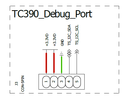
Schaltplan eines Debug-Ports
TC390_Debug_Port +3.3VD +3.3VD GND TS_I2C_SDA TS_I2C_SCL J3 CON-5PIN 1 2 3 4 5
in „Weitere Informationen zu Touch-Controller TC390“ · Mikrocontroller und Digitale Elektronik · · Schaltpläne
-
PDF
CP2103.pdf
: Pins can be left unconnected when not used. 8 Rev. 1.0 CP2103 D R R D D S S D D D T R R C 8 7 6 5 4 3 2 SGND 2 2 2 2 2 2 2 RI 1 21 NC GND 2 20 NC D+ 3 19 GPIO.0 CP2103 D- 4 18 GPIO.1 Top View VIO 5 17 GPIO.2 VDD 6 16 GPIO.3 SGND REGIN 7 15 NC 8 9 0 1 2 3 4 1 1 1 1 1 S T C D D C C B R N E E N N V P P U U S S Figure 2. QFN-28 Pinout Diagram (Top View) Rev. 1.0 9 CP2103 Figure 3. QFN-28 Package Drawing Table
in „Verständnisfrage: CP2103 USB-Uart Bridge“ · FPGA, VHDL & Co. ·
-
PDF
AVR335.pdf
C8 MicrophoneGND 10K GND 4n7 Connector GND GND GND V cc C6 100nF GND C2 C5 1µF 100nF U1D U1C 13 - U1B 9 - 14 C3 5 6 - 8 R11 12 + 1µF 7 R7 R10 10 + LM 324 4 R8 R6 5 LM 324 12K 3 + 1K8 15K C9 C4 2 470R 5K
in „PWM zur Tonausgabe auf einem Lautsprecher Mega8“ · Mikrocontroller und Digitale Elektronik ·
-
PDF
WIZ-EmbeddedWebServser_User_Manual_V1_0_2.pdf
AVR ISP Connector ④ WIZ-Embedded WebServer Module Connector The connector has below pin map. Figure 5. WIZ-Embedded WebServer PIN MAP J3 J2 3.3V 3.3V ADC0/PF0 ADC1/PF1 GND GND ADC2/PF2 ADC3/PF3 SCL/INT0/PD0 SDA/INT0/PD1 ADC4/PF4 ADC5/PF5 RXD1/INT2/PD2 TXD1/INT3/PD3 ADC6/PF6 ADC7/PF7 ICP1/PD4 XCK1/PD5 AREF PB4 T1/PD6 T2/PD7 PB5 PB6 SS/PB0 SCK/PB1 PB7 PE7 MOSI/PB2 MISO/PB3 PE5 PE6 RXD0/PE0 TXD0/PE1 PE3 PE4 GND GND /RESET PE2 Table 3. WIZ-Embedded WebServer PIN MAP © Copyright 2007 WIZnet Inc. All rights
in „[V] Ethernet Webserver mit ATMEGA128 und 2x Ohne MCU“ · Markt ·
-
Datei
sysinit.c
/* ******************************************** Modul : System Init Diverse Einstellungen für den Systemstart und Interrupt Handler Autor : Christian Julius ******************************************** */ /* -------------- System Include Files ------------------- */ #include "stm32f10x_conf.h" #include "system_stm32f10x.h" /* -------------- Standard Include Files ----------------- */ #include <stdbool.h> #include <stdint.h> #include <stdio.h> #include <stdlib.h> /* -------------- Special Include Files / Librarys ------ */ /* -------------- Projekt Include Files ---------------- */ #include "sysinit.h
in „STM32F1xx: Wie GOL am "Leben" halten?“ · Mikrocontroller und Digitale Elektronik ·
-
Datei
_9341uno.ino
//Technical support:goodtft@163.com // Breakout/Arduino UNO pin usage: // LCD Data Bit : 7 6 5 4 3 2 1 0 // Uno dig. pin : 7 6 5 4 3 2 9 8 // Uno port/pin : PD7 PD6 PD5 PD4 PD3 PD2 PB1 PB0 // Mega dig. pin: 29 28 27 26 25 24 23 22 #define LCD_RD A0 #define LCD_WR
in „2.8 TFT von egeloo“ · Mikrocontroller und Digitale Elektronik ·
-
PDF
GCC_Tut_Test.pdf
Tipparbeit 8 aber ubersichtlicher und selbsterkl arend: */ 9 DDRB = (1 << DDB0) | (1 << DDB1) | (1 << DDB2) | (1 << DDB3) | (1 << DDB4); 10 ... ▯ ▯ ▯Die Pins 5 bis 7 werden (da 0) als Eingan e geschaltet. Weitere Beispiele: ▯ 1 // Alle Pins des Ports B als Ausgang definieren: 2 DDRB = 0xff; 3 // Pin0 wieder
-
Datei
lcd.c
// Ansteuerung eines HD44780 kompatiblen LCD im 4-Bit-Interfacemodus // http://www.mikrocontroller.net/articles/HD44780 // http://www.mikrocontroller.net/articles/AVR-GCC-Tutorial/LCD-Ansteuerung // // Die Pinbelegung ist über defines in lcd-routines.h einstellbar #include <avr/io.h> #include "lcd.h" #include <stdlib.h> #include <util/delay.h> //////////////////////////////////////////////////////////////////////////////// // Erzeugt einen Enable-Puls static void lcd_enable( void ) { LCD_PORT |= (1<<LCD_EN); // Enable auf 1 setzen _delay_us( LCD_ENABLE_US ); // kurze Pause LCD_PORT &= ~(1<<LCD_EN
-
Datei
lcd-routines.c
// Ansteuerung eines HD44780 kompatiblen LCD im 4-Bit-Interfacemodus // http://www.mikrocontroller.net/articles/HD44780 // http://www.mikrocontroller.net/articles/AVR-GCC-Tutorial/LCD-Ansteuerung // // Die Pinbelegung ist über defines in lcd-routines.h einstellbar #include <avr/io.h> #include "lcd-routines.h" #include <util/delay.h> //////////////////////////////////////////////////////////////////////////////// // Erzeugt einen Enable-Puls static void lcd_enable( void ) { LCD_PORT |= (1<<LCD_EN); // Enable auf 1 setzen _delay_us( LCD_ENABLE_US ); // kurze Pause LCD_PORT &= ~(1<<LCD_EN); // Enable auf
in „EA DOG 3,3V 4bit (AVR-GCC-Tutorial/LCD-Ansteuerung)“ · Mikrocontroller und Digitale Elektronik ·
-
PDF
DCL10_ds593.pdf
of Cascaded Slave-Serial Topology DS593 (v1.2.1) March 17, 2011 www.xilinx.com 17 Platform Cable USB II X-Ref Target - Figure 18 + 3.3V 2 mm Connector 2 V REF 8 MISO 10 MOSI 4 SS 6 SCK 13 PGND * (4) GND +2.5V +3.3V +1.2V +3.3V V V V V C C C C A O O I U _ _ T X 2 0 VCC MOSI D W ‘1’ (5) DIN SPI Bus Q ST Micro Spartan-3E(2) M25Pxx (1) SPI Flash FPGA CSO_B S HOLD ‘1’ CCLK C + 2.5V GND ( k . 4 GND PROG_B DS593_18_021508 Notes: 1. The pin names for a ST Microsystems
in „USBprog CPLD Starterkit Wie bauen?“ · FPGA, VHDL & Co. ·
-
PDF
User_guide_-_Driver.pdf
1, and so on. Returns: None. 9.2.2.21 GPIOPinTypeI2C Configures pin(s) for use by the I2C peripheral. Prototype: void GPIOPinTypeI2C(unsigned long ulPort, unsigned char ucPins) Parameters: ulPort is the base address of the GPIO port.
in „PCF8574 mit LM3S8938 per I2C auslesen“ · Mikrocontroller und Digitale Elektronik ·
-
PDF
Porting_ucOSII_to_ARM.pdf
. . . 39 4.1.1 Port header; os cpu.h . . . . . . . . . . . . . . . . . . . . . . . . . . . . . . . 41 4.1.2 Port C-functions; os cpu c.c . . . . . . . . . . . . . . . . . . . . . . .. . . . 41 4.1.3 Port assembler-functions
in „uC/OS-II portieren“ · Mikrocontroller und Digitale Elektronik ·