-
Datei
input.txt
STM32F746ZGT6 PE2 PE3 PE4 PE5 PE6 VBAT PC13 PC14 PC15 PF0 PF1 PF2 PF3 PF4 PF5 VSS VDD PF6 PF7 PF8 PF9 PF10 PH0 PH1 NRST PC0 PC1 PC2 PC3 VDD VSSA VREF+ VDDA PA0 PA1 PA2 PA3 VSS VDD PA4 PA5 PA6 PA7 PC4 PC5
-
Datei
main.h
#endif /* Includes ------------------------------------------------------------------*/ #include "stm32u5xx_hal.h" /* Private includes ----------------------------------------------------------*/ /* USER CODE BEGIN Includes */ /* USER CODE END Includes */ /* Exported types --------------------------
in „STM32U599 reagiert nicht: Keine Funktion auf dem Custom Board“ · Mikrocontroller und Digitale Elektronik ·
-
 Bild
Bild
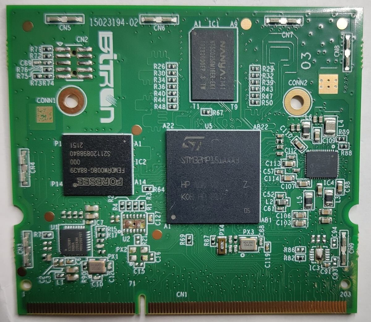
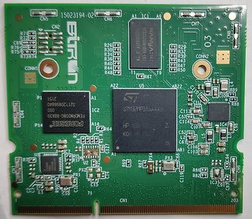
Leiterplatte mit STM32MP15A3 Prozessor
AB22 C110 C112 C113 C114 C107 C57 IC4 C8 R89 C109 R88 P14 S21120898840 000 FEMDRW006G-88A39 AI C2 STM32MP15A3 HP KOR Z C52 L2 C61 IC4 AB1 C106 C193 C94 CN9 R86 R82 IC3 C93 CN1 P14 R64 R63 R62 R61 R60 R59 R58 R57 R56 R55 R54 R53 R52 R51 R50 R49 R48 R47 R46 R45 R44 R43 R42 R41 R40 R39 R38 R37 R36 R35
in „free2move eProWallbox Reverse Engineering (OEM Bitron; ISO 15118 (!), Linux)“ · Fahrzeugelektronik · · Platinenfotos
-
Datei
bootloader.ld
application : { . = ALIGN(0x80); /* PM0056, Rev.1 (4/2009), 4.3.3 */ KEEP(*(.bl_jump)) /* Minimalistic STM32 ISR vector table for jumping to bootloader */ . = 4k; . = ALIGN(0x80); /* PM0056, Rev.1 (4/2009), 4.3.3 */ _isr_vectorsflash_offs = . - 0x08000000; KEEP(*(.isr_vector)) /* This is the real bootloader
in „Nicht genutzte globale Variablen werden wegoptimiert“ · Mikrocontroller und Digitale Elektronik ·
-
PDF
resteliste_1.pdf
Tabelle1 Bezeichnung Menge Gehäuse Hersteller Bezeichnung Angebot 24C02 WMN6P 100 SO8 STM 2 KBit (256 x 8 Bit) 8,00 € AD1100A 10 SO8 Analog DevicesDUM1100 iCoupler 5,00 € BSP373 50 SOT223-4 Infineon Small-Signal MOSFET, 100V, SOT-223 5,00 € CA3240 E 50 DIL8 OP AMP DUAL MOS IP/BIPOLAR OPAMP
in „Aufräumen und Reste“ · Markt ·
-
Datei
edm_test.c
edm_variables.h" #include "edm_test.h" #include "../../ioMapping.h" // Alle Ports und Pins #include "stm32f10x_gpio.h" extern uint16_t ADC1ConvertedValues[10]; /* Test der ADC-Routinen (Multiplex und Interrupt-Aufruf) */ void edm_test_adc(void) { printf_P(PSTR("\fTest EDM-ADC \n" "Beenden durch Knopfdruck
in „STM32: Suche Hilfe zu ADC“ · Mikrocontroller und Digitale Elektronik ·
-
Datei
debugger_output.txt
match requested speed 8000 kHz, using 4000 kHz Info : Stlink adapter speed set to 4000 kHz Info : STM32F303RETx.cpu: hardware has 6 breakpoints, 4 watchpoints Info : Listening on port 3333 for gdb connections Info : accepting 'gdb' connection on tcp/3333 target halted due to debug-request, current mode
in „STM32 läuft mit Debugger schneller als er soll“ · Mikrocontroller und Digitale Elektronik ·
-
Datei
main.c
#include <stdint.h> #include "stm32f3xx.h" // delay loop without using a timer // for 48MHz, Latency 1, gcc optimizer enabled void delay_ms(uint32_t msec) { for (uint32_t j=0; j<6000UL*msec; j++) { __NOP(); } } // Change system clock
in „STM32 läuft mit Debugger schneller als er soll“ · Mikrocontroller und Digitale Elektronik ·
-
Datei
io_test.c
Ursachenvorschung" fuer unterschiedliche Geschwindigkeiten beim Set / Reset von GPIO Pins Hardware : STM32F103C8 IDE : make - Projekt Library : libopencm3 Toolchain : arm-none-eabi 18.02.2020 R. Deelig ------------------------------------------------------------- */ #include <stdint.h> #include <stdlib.h
in „STM32F103: Unterschiedliche Puls-Pausezeiten, Pausezeiten länger“ · Mikrocontroller und Digitale Elektronik ·
-
Datei
SST25VF016B.h
SST25VF016B_H /* Includes ------------------------------------------------------------------*/ #include "stm32f4xx.h" /* Private typedef -----------------------------------------------------------*/ typedef enum ERTYPE{Sec1,Sec8,Sec16,Chip} ErType; typedef enum IDTYPE{Manu_ID,Dev_ID,Jedec_ID} idtype; /* Private
in „Font in SPI Flash schreiben“ · Mikrocontroller und Digitale Elektronik ·
-
Datei
main.c
#include <stm32f0xx.h> #include <string.h> int main() { RCC_HSICmd(ENABLE); RCC_HCLKConfig(RCC_SYSCLK_Div1); RCC_PCLKConfig(RCC_HCLK_Div1); RCC_SYSCLKConfig(RCC_SYSCLKSource_HSI); RCC_AHBPeriphClockCmd(RCC_AHBPeriph_GPIOA
in „[STM32F0] Problem mit ungenauem Timer (RX Signal)“ · Mikrocontroller und Digitale Elektronik ·
-
Datei
nrf24l01_usr.c
----- */ #define RX_CMD_HISTORY 0x10 /* -------------- Public Variablen ----------------------- */ stm32f103_data_t actual_data; // Datensatz für Display volatile uint16_t RfTOCnt = 0; /* Flags */ volatile _Bool f_GotData = false; // Es liegen neue Daten vor volatile _Bool f_GotHistory = false; // Daten
in „[STM32F4xx] NRF24L01+ Funkmodul Source Code“ · Projekte & Code ·
-
Datei
irsnd_init.c
void irsnd_init (void) { // STM32 GPIO_InitTypeDef GPIO_InitStructure; TIM_TimeBaseInitTypeDef TIM_TimeBaseStructure; TIM_OCInitTypeDef TIM_OCInitStructure; /* GPIOx clock enable */ RCC_AHBPeriphClockCmd(IRSND_PORT_RCC, ENABLE); /
in „IRSND auf STM32F0“ · Mikrocontroller und Digitale Elektronik ·
-
Datei
TouchPanel.h
TOUCHPANEL_H_ /* Includes ------------------------------------------------------------------*/ #include "stm32f10x.h" /* Private typedef -----------------------------------------------------------*/ typedef struct POINT { uint16_t x; uint16_t y; }Coordinate; typedef struct Matrix { long double An, Bn, Cn,
in „ADS7843 Werte berechnen“ · Mikrocontroller und Digitale Elektronik ·
-
Datei
BitBangingTest.c
#include <stdio.h> #include <stdint.h> #include <stdbool.h> #include "stm32f3xx.h" volatile _Bool interruptWarDa; void TIM2_IRQHandler(void) { interruptWarDa = 1; TIM2->SR &= ~TIM_SR_UIF; } // Function to delay in microseconds void Delay(uint32_t x){ RCC->APB1ENR |= RCC_APB1ENR_TIM2EN
in „Bit Banging STM32 - F303RE ohne Library“ · Mikrocontroller und Digitale Elektronik ·
-
PDF
Minilabortisch.pdf
Mosfet LDO h s , 4 Kippschalter O t b O 4 + Mosfet Mosfet 3,3 V I r e I + x n b n x ( l m r n ( i p c STM32 LEDs f p i i c 1 Display Display l o e r a Miniatur P K Elektronik r e B Kippschalter e ti i n Poti f s S c B 4 cm Drehencoder 10 cm 2 cm 2 cm 2 cm 10 cm 14 cm
in „Mobiler modularer Microlabortisch in Brotbüchse“ · Mechanik, Gehäuse, Werkzeug ·
-
 Bild
Bild
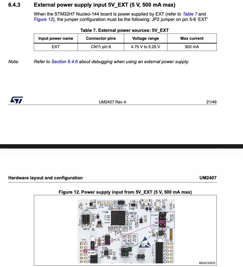
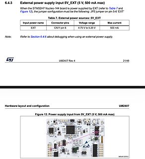
Ausschnitt aus einem Datenblatt mit Tabelle und Leiterplatten-Layout
6.4.3 External power supply input 5V_EXT (5 V, 500 mA max) When the STM32H7 Nucleo-144 board is power supplied by EXT (refer to Table 7 and Figure 12), the jumper configuration must be the following: JP2 jumper on pin 5-6 'EXT' Table 7. External power sources: 5V_EXT EXT
in „L7805 überhitzt bei bestimmten Last-Szenarien“ · Analoge Elektronik und Schaltungstechnik · · Screenshots
-
 Bild
Bild
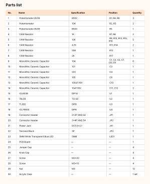
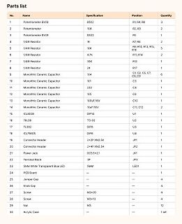
Teileliste einer Bausatz-Dokumentation
22 Connector Header 2x4P XM2.54 JP2 1 23 Power Jack DC5.5x2.1 JK1 1 24 Terminal Block 3P JP3 1 25 STM32 White Transparent Blue LED SMD LED1 1 26 PCB Board -- -- 1 27 Jumper Cap -- -- 4 28 Knob Cap -- -- 4 29 Screw M3x20 -- -- 4 30 Screw M3x10 -- -- 4 31 Nut M3 -- -- 12 32 Acrylic Case -- -- 1 stk
in „Sinusgenerator Bausatz ohne / mit fehlerhafter Stückliste“ · Analoge Elektronik und Schaltungstechnik · · Screenshots
-
Datei
main.c
#include "stm32f4xx.h" TIM_TimeBaseInitTypeDef TIM_TimeBaseStructure; TIM_OCInitTypeDef TIM_OCInitStructure; uint16_t TimerPeriod = 0; void TIM_GPIO_Config(void); int main(void) { TIM_GPIO_Config(); TimerPeriod =
in „STM32F4 einfache PWM“ · Mikrocontroller und Digitale Elektronik ·
-
Datei
blink.c
#include "stm32f4xx.h" void TIM1_UP_TIM10_IRQHandler () { TIM10->SR = (uint16_t)~TIM_IT_Update; GPIOD->ODR ^= (1 << 14); } int main () { // Init GPIO's for LED's RCC_AHB1PeriphClockCmd(RCC_AHB1ENR_GPIODEN, ENABLE
in „STM32F4: Timerinterrupts nichtdeterministisch“ · Mikrocontroller und Digitale Elektronik ·
-
Datei
CAN_Config.h
* @version 3.3.0 * @date 19-Nov-2012 12:11 * @brief This file contains motor parameters needed by STM32 PMSM MC FW * library v3.0 ****************************************************************************** * @attention * * <h2><center>© COPYRIGHT 2012 STMicroelectronics</center></h2> * * Licensed
in „STM32F4 - CAN1 empfängt nichts“ · Mikrocontroller und Digitale Elektronik ·
-
Datei
edm_test.c
edm_variables.h" #include "edm_test.h" #include "../../ioMapping.h" // Alle Ports und Pins #include "stm32f10x_gpio.h" extern uint16_t ADC1ConvertedValues[10]; volatile uint16_t gl_a; volatile uint16_t gl_b; /* Test der ADC-Routinen (Multiplex und Interrupt-Aufruf) */ void edm_test_adc(void) { printf_P
in „STM32: Suche Hilfe zu ADC“ · Mikrocontroller und Digitale Elektronik ·
-
Datei
edm_test.c
edm_variables.h" #include "edm_test.h" #include "../../ioMapping.h" // Alle Ports und Pins #include "stm32f10x_gpio.h" extern uint16_t ADC1ConvertedValues[10]; volatile uint16_t gl_a; volatile uint16_t gl_b; /* Test der ADC-Routinen (Multiplex und Interrupt-Aufruf) */ void edm_test_adc(void) { printf_P
in „STM32 - ADC-DMA1-IRQ-Handler macht Unsinn“ · Mikrocontroller und Digitale Elektronik ·
-
Datei
i2c_ee.h
I2C_EE_H /* Includes ------------------------------------------------------------------*/ #include "stm32f10x.h" /* Exported types ------------------------------------------------------------*/ /* Exported constants --------------------------------------------------------*/ /* The M24C02W contains 256
in „STN32 I2C EEprom AT24C02“ · Mikrocontroller und Digitale Elektronik ·
-
Datei
main.h
#endif /* Includes ------------------------------------------------------------------*/ #include "stm32f0xx_hal.h" /* Private includes ----------------------------------------------------------*/ /* USER CODE BEGIN Includes */ /* USER CODE END Includes */ /* Exported types --------------------------
in „LCD W204B-NLW“ · Mikrocontroller und Digitale Elektronik ·
-
Datei
quelltext2.c
#include <stdio.h> #include "../CMSIS/device/stm32f3xx.h" // The current clock frequency uint32_t SystemCoreClock=8000000; // Counts milliseconds volatile uint32_t systick_count=0; // Interrupt handler void SysTick_Handler(void) { systick_count++;
in „STM32 läuft mit Debugger schneller als er soll“ · Mikrocontroller und Digitale Elektronik ·
-
Datei
index.shtml
id="content"> <p> <div id="datum"> </div> <br> <div id="txt"></div> <br> </p> <p> ARM-Webserver mit STM32F103ZET6 und ENC28J60 <br> Basierend auf den uIP TCP/IP Stack<br><br> Erweiterungen <br> <ul> <li>Lampensteuerung</li> <li>ALLE 3 SEKUNDEN WIRD DIE SEITE AKTUALISIERT</li> <li>LED-Steuerung</li> <li
in „uIP BUTTON an aus“ · Mikrocontroller und Digitale Elektronik ·
-
Datei
oneWire.h
***/ /* Includes **********************************************************************/ #include "stm32f10x_conf.h" /* Defines **********************************************************************/ #define OW_Enable_Port GPIOB #define OW_Enable GPIO_Pin_12 #define OW_Data_Port GPIOB #define OW_Data
in „Timingproblem mit Onewire und STM32“ · Mikrocontroller und Digitale Elektronik ·
-
Datei
LedVuMeter.ino
// LED VU-Meter // turns on the LEDs depending on the sound level detected from the microphon // STM32F4 Discovery #define USERBUTTON PA0 #define GREENLED PD12 #define ORANGELED PD13 #define GREDLED PD14 #define BLUELED PD15 #define REDLEDOTGOVERCURRENT PD5 #define MICROPHON_CLK_INPUT PB10 #define
in „STM32F4 Discovery Arduino“ · Mikrocontroller und Digitale Elektronik ·
-
Datei
debug.c
===================================================================== #include "debug.h" #include "stm32f4xx.h" //============================================================================= // Main output routine //============================================================================= void SWV_puts
in „STM32: Drama mit "Hard Fault Error"“ · Mikrocontroller und Digitale Elektronik ·
-
PDF
Log_24h.pdf
delay_init... board_led_init... button_init... timer2_init... wpsbutton_init... Version: 2.9.4 Hardware: STM32F103 Display: WC24h LEDs: SK6812 RGBW rtc is online eeprom is online sk6812: external pullup detected eeprom is online current eeprom version: 0x00020900 reading ir codes from eeprom DFPLAYER LOGGER
-
Datei
mp3_audio.c
DMA_Init(AUDIO_MAL_DMA_STREAM, &DMA_InitStructure); /* Enable the selected DMA interrupts (selected in "stm32_eval_audio_codec.h" defines) */ #ifdef AUDIO_MAL_DMA_IT_TC_EN DMA_ITConfig(AUDIO_MAL_DMA_STREAM, DMA_IT_TC, ENABLE); #endif /* AUDIO_MAL_DMA_IT_TC_EN */ #ifdef AUDIO_MAL_DMA_IT_HT_EN DMA_ITConfig(
in „STM32F429 WM8789 MP3“ · Mikrocontroller und Digitale Elektronik ·
-
Datei
mp3_audio.c
DMA_Init(AUDIO_MAL_DMA_STREAM, &DMA_InitStructure); /* Enable the selected DMA interrupts (selected in "stm32_eval_audio_codec.h" defines) */ #ifdef AUDIO_MAL_DMA_IT_TC_EN DMA_ITConfig(AUDIO_MAL_DMA_STREAM, DMA_IT_TC, ENABLE); #endif /* AUDIO_MAL_DMA_IT_TC_EN */ #ifdef AUDIO_MAL_DMA_IT_HT_EN DMA_ITConfig(
in „STM32F429 WM8789 MP3“ · Mikrocontroller und Digitale Elektronik ·
-
Datei
syscalls.c
include <errno.h> #include <stdlib.h> /* abort */ #include <sys/types.h> #include <sys/stat.h> #include "stm32f10x.h" /* for _get_PSP() from core_cm3.h*/ #undef errno extern int errno; int _kill(int pid, int sig) { pid = pid; sig = sig; /* avoid warnings */ errno = EINVAL; return -1; } void _exit(int status
in „Undefined reference error (yagarto/msys/gcc)“ · µC & Digital Electronics ·
-
Datei
main.c
#include <stdio.h> #include "stm32f3xx.h" #include "usb.h" // The current clock frequency uint32_t SystemCoreClock=8000000; // Counts milliseconds volatile uint32_t systick_count=0; // Interrupt handler void SysTick_Handler(void) {
in „An W.S.: Läuft deine USB Implementierung auch auf STM32F303?“ · Mikrocontroller und Digitale Elektronik ·
-
Datei
quelltext.c
#include <stdint.h> #include "stm32f3xx.h" // The current clock frequency uint32_t SystemCoreClock=8000000; // Counts milliseconds volatile uint32_t systick_count=0; // Interrupt handler void SysTick_Handler(void) { systick_count++;
in „STM32 läuft mit Debugger schneller als er soll“ · Mikrocontroller und Digitale Elektronik ·
-
Datei
Adc.c
#include "Adc.h" #include "stm32f4xx_adc.h" void Adc_Init(void) { ADC_InitTypeDef ADC_InitStructure; ADC_CommonInitTypeDef ADC_CommonInitStructure; GPIO_InitTypeDef GPIO_InitStructure; RCC_APB2PeriphClockCmd(RCC_APB2Periph_ADC1,
in „STM32F4 Internal Reference“ · Mikrocontroller und Digitale Elektronik ·
-
Datei
can.c
#include "stm32f10x.h" #include "can.h" uint8_t can_init(void) { CAN_InitTypeDef CAN_InitStructure; // enable Clock RCC_APB1PeriphClockCmd(RCC_APB1Periph_CAN1, ENABLE); RCC_APB2PeriphClockCmd(RCC_APB2Periph_GPIOA
in „stm32f103 CAN-Interface“ · Mikrocontroller und Digitale Elektronik ·
-
 Bild
Bild
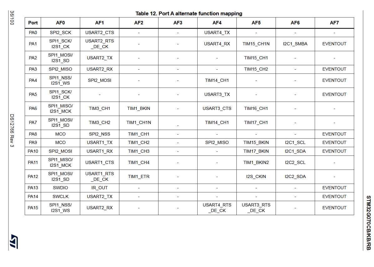
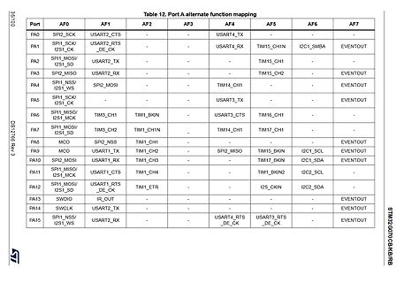
Tabelle der alternativen Port-Funktionszuweisungen eines Mikrocontrollers
USART2_TX - - - EVENTOUT PA15 SPI1_NSS/I2S1_WS USART2_RX - - USART4_RTS_DE_CK USART3_RTS_DE_CK EVENTOUT STM32G070CB/KB/RB
in „UART und I2C Konflikt mit STM32duino STM32G070“ · Mikrocontroller und Digitale Elektronik · · Screenshots
-
Datei
jlink.txt
0x4BA00477, IRLen: 04, IRPrint: 0x1, CoreSight JTAG-DP (ARM) #1 Id: 0x06413041, IRLen: 05, IRPrint: 0x1, STM32 Boundary Scan Cortex-M4 identified. JTAG speed: 100 kHz J-Link>h WARNING: CPU could not be halted J-Link>
in „[STM32/Cortex-M4] JTag nur beim Systemflash möglich. Fehler beim Mainflash“ · Mikrocontroller und Digitale Elektronik ·
-
Datei
main.c
#include <stdio.h> #include "stm32f3xx.h" #include "usb.h" // The current clock frequency uint32_t SystemCoreClock=8000000; // Counts milliseconds volatile uint32_t systick_count=0; // Interrupt handler void SysTick_Handler(void) {
in „An W.S.: Läuft deine USB Implementierung auch auf STM32F303?“ · Mikrocontroller und Digitale Elektronik ·
-
Datei
main.c
#include <stdlib.h> #include <stm32g031xx.h> /*! * \brief Configures pin 5 ("PA11") as digital output. */ void config_output(void) { RCC->IOPENR |= RCC_IOPENR_GPIOAEN; GPIOA->MODER &= ~(0x3u << (11 * 2)); GPIOA->MODER |= (0x1u << (11
in „Crash @ TIM2-Überlauf statt TIM2_IRQHandler (STM32G031J6)“ · Mikrocontroller und Digitale Elektronik ·
-
Datei
main.txt
nc 8 nc nc 9 nc nc 10 nc nc 11 D4 PD0 12 D5 PD1 13 D6 PD2 14 D7 PD3 15 nc nc 16 nc nc */ #include "stm32f4xx.h" uint32_t i; void WriteNibble(char data){ GPIOD->BSRRL |= data; GPIOD->BSRRH |= ~data; GPIOD->BSRRL |= (1<<6); //E=1; for (i=0;i<10000;i++){} //delay GPIOD->BSRRH |= (1<<6); //E=0; for (i=0;
in „STM32: Ich finde einfach keinen Fehler in meinem Code“ · Mikrocontroller und Digitale Elektronik ·
-
Datei
tim.h
#endif /* Includes ------------------------------------------------------------------*/ #include "stm32f4xx_hal.h" /* USER CODE BEGIN Includes */ /* USER CODE END Includes */ extern TIM_HandleTypeDef htim5; extern TIM_HandleTypeDef htim9; /* USER CODE BEGIN Private defines */ /* USER CODE END Private
in „STM32F4 HAL TIMER Interrupt läuft nicht“ · Mikrocontroller und Digitale Elektronik ·
-
Datei
delay.c
#include "delay.h" #include "stm32f0xx_hal.h" // For store tick counts in us static __IO uint32_t usTicks; /** System Clock Configuration */ void SystemClock_Config(uint32_t sysTickDevider) { RCC_OscInitTypeDef RCC_OscInitStruct; RCC_ClkInitTypeDef
in „Interrupt wird ständig aufgerufen“ · Mikrocontroller und Digitale Elektronik ·
-
Datei
8.txt
Model Family: Seagate Maxtor DiamondMax 21 Device Model: MAXTOR STM380215AS Serial Number: 9QZ7D8QL Firmware Version: 4.AAB User Capacity: 80,026,361,856 bytes [80.0 GB] Sector Size: 512 bytes logical/physical Device is: In smartctl database [for details use: -P show
in „[V] SATA SSD/HDDs“ · Markt ·
-
Datei
log.txt
delay_init... board_led_init... button_init... timer2_init... wpsbutton_init... Version: 2.9.4 Hardware: STM32F103 Display: WC12h LEDs: WS2812 GRB rtc is online eeprom is online ws2812: external pullup detected eeprom is online current eeprom version: 0x00020900 reading ir codes from eeprom DFPLAYER LOGGER
-
PDF
Schaltplan.pdf
PA2 1k 2 R3 BC337-40 1 3 PA3 1k Q4 Minuten Einer R4 2 BC337-40 3 GND Binäruhr mit Blue-Pill Board (STM32F103C8T6) 14.10.2017 1.0
-
PDF
Schematic_Smart_Greenhouse_20200410231436.pdf
INPUT2 INPUT3 10 8 9 VS ENABLE2 D D Power Supply 230V AC to 12V / 5V DC RND 205-00035 +12V L7805CV-DG STM +5V 1 2 3 1 3 1 2 1 AC/N +V 4 IN OUT 2 3 AC/L -V GND 3 C1 C3 C4 C2 IRM-15-12 100u 100n 2 100n 100u GND RND 205-00035 1 E 1 2 E 2 3 3 TITLE: Smart Greenhouse REV: 1.1 Company: Sheet: 1/1 Date: 2020-04
in „ESP 32 Schaltung“ · Mikrocontroller und Digitale Elektronik ·
-
Datei
PWM_code.c
#include "stm32f10x_conf.h" unsigned int Sinus[20]= {32768,42893,52028,59277,63931,65535,63931,59277,52028,42893, 32768,22642,13507,6258,1604,0,1604,6258,13507,22642}; int i =0; int main(void) { GPIO_InitTypeDef
in „Sinuswerte für PWM berechnen“ · Mikrocontroller und Digitale Elektronik ·