-
Datei
ASKTimer.c
)((*befehl>>i)&0x01)); } IR_LED_OFF; _delay_ms(70); _delay_ms(70); _delay_ms(17); //Pause zwischen 2 Paketen; } SIGNAL (SIG_OUTPUT_COMPARE1A) { // PinA1 76000 mal in der sek an und ausschalten IR_LED_PORT ^= (1 << IR_LED_PIN); _delay_us(180); _delay_us(150); // Ein Bit dauert 330 us } int main(void) { Timer1(); // PortA als Ausgang IR_LED_DDR|= (1 << IR_LED_PIN ); while(1) { PORTC=(1<<PC0); // interner PullUp Widerstand von PortC.0 wird aktiviert if (!(PINC & (1<<PC0)) > 0) // Ist der Taster0 gedrückt? { IRSend(&Power1befehl
in „Infrarot senden“ · Mikrocontroller und Digitale Elektronik ·
-
PDF
Eurotec.pdf
alloy; Finish: bright electro-tin type l, .0003 in. thick min.; Cover material: cupro-nickel. PIN OUT TABLE — Power Splitter Pin-Out Sum Port Port 1 Port 2 Ground Terminate 50 Ohms 1 1 5 B 2 ,3 ,4 ,7 ,8 — 2 1 2 5 3 ,4 ,7 ,8 6 6 1 4 5 2 ,3 ,6 ,7 ,8 — See Pin Numbers above. E U R O T E C - T H E E
in „Distributor für M/A-COM in Deuschland“ · HF, Funk und Felder ·
-
Datei
cam.c
*/ unsigned char Port; unsigned char Reg0; unsigned char Reg1; unsigned char Reg2; unsigned char Reg3; unsigned char Reg4; unsigned char Reg5; unsigned char Reg6; unsigned char Reg7; void setPort( unsigned char Port) { i2cStart
in „Gameboy Kamera Modul“ · Mikrocontroller und Digitale Elektronik ·
-
PDF
K7S41-K7S41GX.pdf
Internal Audio Connector: AUX1 (White) 15 System Panel Connector (PANEL1) 30 FID Jumpers (FID0, FID1, FID2, FID3, FID4) 8 1.5 ASRock I/O TM (K7S41 / K7S41GX) 1 Parallel Port 6 Line Out (Lime) 2 RJ-45 Port 7 USB 2.0 Ports 3 Game Port 8 VGA Port 4 Microphone (Pink) 9 PS/2 Keyboard Port (Purple) 5 Line In (Light
in „Asrock Board K7S41 mit SATA 1 Terabyte Festplatte“ · PC Hard- und Software ·
-
Datei
par2ser_at89xxxx.asm
;Red LED - send pin low to light LED L2 equ P1.0 ;Pads L2-L9 may be LEDs or wires to other I/O L3 equ P1.1 L4 equ P1.2 L5 equ P1.3 L6 equ P1.4 L7 equ P1.5 L8 equ P1.6 L9 equ P1.7 L10 equ P3.4 ;Green LED - send pin low
in „seriell2parallel converter II“ · Mikrocontroller und Digitale Elektronik ·
-
Datei
rfm70.c
-2M,out power 5dbm,setup LNA gain high (0dBM) { (0x20 | 0x07), 0x00 }, // { (0x20 | 0x08), 0x00 }, // { (0x20 | 0x09), 0x00 }, // { (0x20 | 0x0C), 0xc3 }, //LSB Addr pipe 2 { (0x20 | 0x0D), 0xc4 }, //LSB
in „RFM70 Timing Problem?“ · Mikrocontroller und Digitale Elektronik ·
-
Datei
W5500_SPI.c
#define NOP1 asm volatile ( "nop" "\n" ); #define W5500_CS_Pin LL_GPIO_PIN_4 #define W5500_CS_GPIO_Port GPIOA #define W5500_IRQ_Pin LL_GPIO_PIN_2 #define W5500_IRQ_GPIO_Port GPIOB #define W5500_CS_LOW LL_GPIO_ResetOutputPin (W5500_CS_GPIO_Port, W5500_CS_Pin); #define W5500_CS_HIGH LL_GPIO_SetOutputPin (W5500_CS_GPIO_Port, W5500_CS_Pin); // W5500 Data Modes #define OM10_VDM 00 /* variable data mode */ #define OM10_FDM1 01 /* fixed data mode, 1 byte */ #define OM10_FDM2 10 /* fixed data mode, 2 byte
in „Wiznet W5500 Datenübertragung via Ethernet“ · Mikrocontroller und Digitale Elektronik ·
-
Datei
ws2801_sample.c
#include <util/delay.h> #define CLOCK_DDR DDRB #define CLOCK_PORT PORTB #define CLOCK_PIN PB5 #define DATA_DDR DDRB #define DATA_PORT PORTB #define DATA_PIN PB3 void ws2801_init() { // Init Clock Pin CLOCK_DDR |= (1<<CLOCK_PIN); CLOCK_PORT &= ~(1<<CLOCK_PIN); // Init Data Pin DATA_DDR |= (1<<DATA_PIN); DATA_PORT &= ~(1<<DATA_PIN); } void ws2801_sendRGB(uint8_t* rgb, uint16_t num) { // Start transmission for(uint8_t i=0; i<(num*3); i++) // 3 Byte per LED { for(uint8_t bit=0x80; bit; bit >>= 1) { if(rgb[i] & bit) DATA_PORT |= (1<<DATA_PIN); else DATA_PORT &= ~(1<<DATA_PIN); CLOCK_PORT |= (1<<CLOCK_PIN
-
Datei
web.html
\"D\" %PORTC3>\r\n" "<span class=\"Stil2\">Port C Pin 3</span></p>\r\n" "<p><input type=\"checkbox\" name=\"OUT\" value=\"E\" %PORTC4>\r\n" "<span class=\"Stil2\">Port C Pin 4</span></p>\r\n" "<p><input type=\"checkbox\" name=\"OUT\" value=\"F\" %PORTC5>\r\n" "<span class=\"Stil2\">Port C Pin 5</span></p>\r\n" "<p><input type=\"checkbox\" name=\"OUT\" value=\"G\" %PORTC6>\r\n" "<span class=\"Stil2\">Port C Pin 6</span></p>\r\n" "<p><input type=\"checkbox
-
Datei
NanoEveryRegister.h
ADC0 | Pin Port | Port | Channel | default | PortMux | default | PortMux | default | PortMux | default | 0 PC5 | 0 2 or 3 | --- --- | --- 0-WO5 | --- --- | | 1 PC4 | 0 2 or 3 | --- --- | --- 0-WO4 | --- --- |
in „Fehlerhafte Adressierung von lokalen Arrays bei tinyAVR(R) 0-series“ · Mikrocontroller und Digitale Elektronik ·
-
Datei
LCD_driver.c
********************************************* void ioinit(void) { //* setup the switches for input pinMode(kSwitch1_PIN, INPUT); pinMode(kSwitch2_PIN, INPUT); pinMode(kSwitch3_PIN, INPUT); //* set the pull up resisters digitalWrite(kSwitch1_PIN, HIGH); digitalWrite(kSwitch2_PIN, HIGH); digitalWrite(kSwitch3
in „Arduino Uno mit Sparkfun LCD undefined reference“ · Mikrocontroller und Digitale Elektronik ·
-
Datei
Main.c
// Pin 5 auf Ausgang und andere im ursprünglichen Zustand belassen: DDRD |= (1 << DDD5); DDRC |= (1 << DDC2); // Pull Up von Pin 0 und Pin 1 setzen: PORTC = ( 1 << PC0 ) | ( 1 << PC1 ); } /** Main **/ int
in „Funktionsaufruf Funktioniert nicht richtig..warum?“ · Mikrocontroller und Digitale Elektronik ·
-
Datei
laptime.c
mit Null überschreiben #define CURSOR_HOME 0x02 // Coursor an Anfangsposition setzen #define LCD_PORT PORTD // Port an dem das LCD angeschlossen ist #define LCD_DDR DDRD // Datenpins an denen das LCD angeschlossen ist #define LCD_RS PD4 // Ausgang an dem der RS-Pin des LCD hängt #define LCD_EN PD5 /
in „LCD Ausgabe dauert zu lange“ · Mikrocontroller und Digitale Elektronik ·
-
Datei
ds18s20.c
(pDS18x20->DS18x20_PIN); _delay_us(480); *(pDS18x20->DS18x20_PORT-1) &= ~(_BV(pDS18x20->DS18x20_PIN)); _delay_us(80); result = (*(pDS18x20->DS18x20_PORT-2)) & (_BV(pDS18x20->DS18x20_PIN)); _delay_us(400); return result; }
in „Timerberechnung die hunderste“ · Mikrocontroller und Digitale Elektronik ·
-
Datei
main.c
/************************************************************************/ /* */ /* SEGA Master System 2 */ /* 60Hz Switcher */ /* */ /************************************************************************/ #include <avr/io.h> #include <avr/interrupt.h> #ifndef F_CPU #define F_CPU 9600000 // Processor Frequenz #warning kein F_CPU definiert #endif // CPU: ATtiny13V 9.6MHz // ======================================================================= #define TASTER_DDR DDRB #define TASTER_PORT PORTB #define TASTER_PIN PINB #define TASTER 0 #define ALL_TASTER (1<<TASTER) #define REPEAT_MASK (1<<TASTER)
in „Tastenabfrage mit ATtiny13V“ · Mikrocontroller und Digitale Elektronik ·
-
Datei
main.c
/************************************************************************/ /* */ /* SEGA Master System 2 */ /* 60Hz Switcher */ /* */ /************************************************************************/ #include <avr/io.h> #include <avr/interrupt.h> #ifndef F_CPU #define F_CPU 9600000 // Prozessor Frequenz #warning kein F_CPU definiert #endif // CPU: ATtiny13V 9.6MHz // ======================================================================= #define TASTER_DDR DDRB #define TASTER_PORT PORTB #define TASTER_PIN PINB #define TASTER 0 #define ALL_TASTER (1<<TASTER) #define REPEAT_MASK (1<<TASTER)
in „Tastenabfrage mit ATtiny13V“ · Mikrocontroller und Digitale Elektronik ·
-
Datei
main.c
#include <avr/io.h> #include <uart.h> #include <stdlib.h> #define SYSCLK 3686400 #define BAUD 9600UL #define UBRR_BAUD ((SYSCLK/(16*BAUD))-1) int status; int crash; int light; int crashcounter; void uart_init(void); void adc_init(void); int main(void) { init(); if (status == 0) { sleep(); } else { uart_puts("\r\nInit OK!\r\n"); } while (status != 0) { PrintInt(readadc()); chklight(); // Prüfe Helligkeit, wenn Umgebung dunkel ist >> Beleuchtung EIN if (light != 1) { uart_puts("\r\nLicht EIN!\r\n"); } chkcrash(); //Prüfe Kollisionsstatus if (crash == 0) { motorR(1); motorL(0); } else { uart_puts("\r\nMotoren
in „Infrarot Distanzsensor AD-Wandler, Bitte Source Code Prüfen“ · Mikrocontroller und Digitale Elektronik ·
-
PDF
A600_v2.1_Amplifier_Kit_full_assembly_instructions-2.pdf
, 2 Vsense (output) increases with approx. 0.0485V for every 1V at the supply. For 48V this pin should provide about 2.33V output. 3 GND Supply ground Voltage directly proportional to the PA Unit current
-
PDF
edip128-6e.pdf
input of the host system, for example.. I²C - Address Pin 11,7,6 Base I²C address address D7 D6 D5 D4 D3 D2 D1 D0 BA2 BA1 BA0 L L L $10 0 0 0 1 L L H $20 0 0 1 0 L H L $30 0 0 1 1 S S S L H H $40 0 1 0 0 A A A R H L L $70 0 1 1 1 2 1 0 W H L H
-
Datei
880eed3fe10373c0a5d4ca8d0892cc67.txt
CONF_WATCHASYNC_SUMMARIZE is not set CONF_WATCHASYNC_BUFFERSIZE=64 # CONF_WATCHASYNC_EDGDETECTVIAPOLLING is not set # # Pin Configuration # # # Port A # # CONF_WATCHASYNC_PA0 is not set # CONF_WATCHASYNC_PA1 is not set # CONF_WATCHASYNC_PA2 is not set # CONF_WATCHASYNC_PA3 is not set # CONF_WATCHASYNC_PA4 is not set # CONF_WATCHASYNC_PA5
in „Ethersex will nicht so richtig“ · Mikrocontroller und Digitale Elektronik ·
-
PDF
ADNS-3080-Avago.pdf
D - D - P0.7* SCLK 5 1.3 KΩ LED_CTRL GND 11 Vreg P0.6 22 2 MISO 8 17 3 P1.7 P0.5* 23 4 S 13 18 C MOSI D REFC Vcc SHLD P1.5 S - P0.4* 24 1 A + 2.2 E 3 NCS uF 3 P 7 3 10 KΩ 6 REFB 14 Vcc C C P0.2 RESET Scroll Wheel Y 4 10
in „ADNS3080 Steuerung“ · Mikrocontroller und Digitale Elektronik ·
-
Datei
ASR13_nur_Bus.asm
, Fehler bei Addi? ;Addi passt, ;starkes flackern, bei loop ADC weg .INCLUDE "tn13def.inc" ; In= PB5 Pin1 = (Reset) n.c. ; In= PB4 Pin3 = Shunt ADC2 ; In= PB3 Pin2 = Data ; In= PB2 Pin7 = Spannung AComp; 1,023V Schwelle ; In= PB1 Pin6 = Taster; gedrückt = L; für Erprobung Monitor ; Out=PB0 Pin5 = OC0A
in „Hausbus für Meß- und Steueraufgaben mit Attiny“ · Haus & Smart Home ·
-
Datei
NinoFarad.asm
--------------------------------------------------------------------- ;PB0 > - OUT ;PC1 > - OUT ;PB2 > - OUT ;PB3 > - OUT ;PB4 > - OUT ;PB5 > - OUT ;PB6 > Quarz - ;PB7 > Quarz - ;PC0 > LCD Pin register select OUT ;PC1 > LCD Pin read/write OUT ;PC2 > LCD Pin enable OUT ;PC3 > - OUT ;PC4 > - OUT ;PC5
in „Mega8-Timer1 (16bit) scheint nur bis 256 zu zählen“ · Mikrocontroller und Digitale Elektronik ·
-
Datei
vs1011_1.c
USART_BAUD_RATE*16L)-1) //GROß L <<<<<<<<<<<<<<<<<<<<< #define SS 0 #define SCK 7 #define MISO 6 #define MOSI 5 #define BSYNC 2 #define DREQ 3 #define SS_VS 1 #define RST 7 #define SS_PORT PORTB #define SCK_PORT PORTB #define MISO_PORT PORTB #define MOSI_PORT PORTB #define BSYNC_PORT PORTB #define DREQ_PORT PORTB
in „Sinustest des vs1011“ · Mikrocontroller und Digitale Elektronik ·
-
Datei
lcd-routines.c
); lcd_enable(); _delay_ms( LCD_SOFT_RESET_MS2 ); lcd_enable(); _delay_ms( LCD_SOFT_RESET_MS3 ); // 4-bit Modus aktivieren lcd_out( LCD_SET_FUNCTION | LCD_FUNCTION_4BIT ); _delay_ms( LCD_SET_4BITMODE_MS ); // 4-bit Modus / 4 Zeilen / 5x7 lcd_command
in „20x4 LCD an MyAVR Board anbinden“ · Mikrocontroller und Digitale Elektronik ·
-
Datei
bitbang_spi.h
B #define bb_mosi_pin 3 #endif #if bb_port==2 #define bb_sck_port B//m644 #define bb_sck_pin 7 #define bb_miso_port B #define bb_miso_pin 6 #define bb_mosi_port B #define bb_mosi_pin 5 #endif #if bb_port==3 #define bb_sck_port
in „LPC1758 und PN532 über SPI“ · Mikrocontroller und Digitale Elektronik ·
-
Datei
LCD_DEM16216.inc
cbi LCD_Data_Port, PIN_LCD_E rcall delay_5ms sbi LCD_Data_Port, PIN_LCD_E ;thirdth time rcall delay_5ms cbi LCD_Data_Port, PIN_LCD_E rcall delay_5ms ldi temp1, 0b00000010 ;set 4-bit interface mode and wait out LCD_Data_Port, temp1 sbi LCD_Data_Port, PIN_LCD_E rcall delay_5ms cbi LCD_Data_Port, PIN_LCD_E rcall delay_5ms ldi temp1, 0b00101000 ;zwei zeilig und 5*8 Punktdarstellung rcall LCD_Command rcall delay_5ms ;add 2ms for wait of LCD (it must
-
Datei
LCD_DEM16216.inc
cbi LCD_Data_Port, PIN_LCD_E rcall delay_5ms sbi LCD_Data_Port, PIN_LCD_E ;thirdth time rcall delay_5ms cbi LCD_Data_Port, PIN_LCD_E rcall delay_5ms ldi temp1, 0b00000010 ;set 4-bit interface mode and wait out LCD_Data_Port, temp1 sbi LCD_Data_Port, PIN_LCD_E rcall delay_5ms cbi LCD_Data_Port, PIN_LCD_E rcall delay_5ms ldi temp1, 0b00101000 ;zwei zeilig und 5*8 Punktdarstellung rcall LCD_Command rcall delay_5ms ;add 2ms for wait of LCD (it must
-
Datei
laptimer.c
mit Null überschreiben #define CURSOR_HOME 0x02 // Coursor an Anfangsposition setzen #define LCD_PORT PORTD // Port an dem das LCD angeschlossen ist #define LCD_DDR DDRD // Datenpins an denen das LCD angeschlossen ist #define LCD_RS PD4 // Ausgang an dem der RS-Pin des LCD hängt #define LCD_EN PD5 /
in „Laptimer Projekt mit Magnetschleife (Atmega8)“ · Mikrocontroller und Digitale Elektronik ·
-
Datei
lcd-routines.c
// Ansteuerung eines HD44780 kompatiblen LCD im 4-Bit-Interfacemodus // http://www.mikrocontroller.net/articles/HD44780 // http://www.mikrocontroller.net/articles/AVR-GCC-Tutorial/LCD-Ansteuerung // // Die Pinbelegung ist über defines in lcd.h einstellbar #include <avr/io.h> //#include "main.h" #include "lcd.h" #include <util/delay.h> ///////////////////////////////////////////////////////////////////////////////// // Erzeugt einen Enable-Puls static void lcd_enable( void ) { LCD_PORT |= (1<<LCD_EN); // Enable auf 1 setzen _delay_us( LCD_ENABLE_US ); // kurze Pause LCD_PORT &= ~(1<<LCD_EN); // Enable
in „LCD kann nur Kontrast einstellen“ · Mikrocontroller und Digitale Elektronik ·
-
Datei
lcd-routines.c
// Ansteuerung eines HD44780 kompatiblen LCD im 4-Bit-Interfacemodus // http://www.mikrocontroller.net/articles/HD44780 // http://www.mikrocontroller.net/articles/AVR-GCC-Tutorial/LCD-Ansteuerung // // Die Pinbelegung ist über defines in lcd.h einstellbar #include <avr/io.h> #include "lcd-routines.h" #include <util/delay.h> ///////////////////////////////////////////////////////////////////////////////// // Erzeugt einen Enable-Puls static void lcd_enable( void ) { LCD_PORT |= (1<<LCD_EN); // Enable auf 1 setzen _delay_us( LCD_ENABLE_US ); // kurze Pause LCD_PORT &= ~(1<<LCD_EN); // Enable auf
in „Display Ansteuerung - 16 x 4 DotMatrix LCD“ · Mikrocontroller und Digitale Elektronik ·
-
Datei
lcd-routines.c
// Ansteuerung eines HD44780 kompatiblen LCD im 4-Bit-Interfacemodus // http://www.mikrocontroller.net/articles/HD44780 // http://www.mikrocontroller.net/articles/AVR-GCC-Tutorial/LCD-Ansteuerung // // Die Pinbelegung ist über defines in lcd.h einstellbar #include <avr/io.h> #include "lcd-routines.h" #include <util/delay.h> ///////////////////////////////////////////////////////////////////////////////// // Erzeugt einen Enable-Puls static void lcd_enable( void ) { LCD_PORT |= (1<<LCD_EN); // Enable auf 1 setzen _delay_us( LCD_ENABLE_US ); // kurze Pause LCD_PORT &= ~(1<<LCD_EN); // Enable auf
in „DotMatrix 16x4 in C ansteuern“ · Mikrocontroller und Digitale Elektronik ·
-
Datei
dcfm8.c
BYTE Sekunde59; BYTE Inputstring=0; /* const char error[1][7]PROGMEM ={" XX.X "}; const char temp[2][5]PROGMEM ={",5 C",",0 C"}; const char tag[8][3]PROGMEM ={"Mo","Di","Mi","Do","Fr","Sa","So","20"}; const char fuell[5][2]PROGMEM ={"0",".","-"," ",":"}; // Texte für die LCD-Ausgabe im Flash */ char
in „Funk-uhr über AVR Programmieren mit DCF01“ · Mikrocontroller und Digitale Elektronik ·
-
PDF
BLE112_Datasheet.pdf
RX RT CT USART 1 SPI MI MO C SS Alt.2 MI MO C SS USART 1 UART RX TX RT CT Alt.2 RX TX RT CT TIMER 1 4 3 2 1 0 Alt.2 3 4 0 1 2 1 0 TIMER 3 Alt.2 1 0 1 0 TIMER 4 Alt.2 0 DEBUG DC DD OBSSEL 5 4 3 2 1 0 Table 3:Peripheral I/O Pin Mapping
in „BLE112 wer kennt sich mit dem UART aus ?“ · Mikrocontroller und Digitale Elektronik ·
-
PDF
Cypress_CY8C58LP_001-84932_0F-491909.pdf
Ball Name Ball Name Ball Name Ball Name E5 P2[5] L2 VIO1 B2 P3[6] C8 VIO0 G6 P2[6] K2 P1[6] B3 P3[7] D7 P0[4] G5 P2[7] C9 P4[2] C3 P12[0] E7 P0[5] H6 P12[4] E8 P4[3] C4 P12[1] B9 P0[6] K7 P12[5] K1 P1[7] E3 P15[2] D8 P0[7] L8 P6[4] H2 P12[6]
in „UART-Schnittstelle 2x verwenden?“ · Mikrocontroller und Digitale Elektronik ·
-
Datei
main.c
Objekt zu bestimmern. * Das Programm sollte wie folgt funktionieren: * Durch die Tatsache, dass die Pins 5V und GND des HC-SR04 Moduls mit den entsprechenden Pins des STM32F4 Boards verbunden sind, * ist das Modul mit Strom und Spannung versogt und funktionsbereit. * * Durch die Pin PC6 (TIMER 3 Channel
in „STM32F4 Discovery Board: Aufruf Funktionen in Atollic TrueStudio“ · Mikrocontroller und Digitale Elektronik ·
-
Datei
main.c
#define LED1_ON PORTA |= (1<<PA5) //Rot #define LED1_OFF PORTA &= ~(1<<PA5) #define LED1_C PORTA ^= (1<<PA5) #define LED2_ON PORTA |= (1<<PA6) //Gelb #define LED2_OFF PORTA &= ~(1<<PA6) #define LED2_C PORTA ^= (1<<PA6) #define LED3_ON PORTA |= (1<<PA7) //Grün #define LED3_OFF PORTA &= ~(1<<PA7) #define LED3_C PORTA ^= (1<<PA7) #define INT4_PIN 3 #define INT4_DDR DDRB //Moditaster #define TASTER_PIN 1 #define TASTER_PULLUP PORTB #define TASTER_PINPORT PINB //Statusdefinition
in „Master und 3 Slaves, Kommunikation läuft nicht rund Bitte um Hilfe“ · Mikrocontroller und Digitale Elektronik ·
-
Datei
shiftreg_demo.c
------- */ /* ATtiny44 Anschlusspins IC +-----------+ Vcc | 1 14 | GND PCINT8 - XTAL1 - CLKI PB0 | 2 A 13 | PA0 - ADC0 - AREF - PCINT0 PCINT9 - XTAL2 - PB1 | 3 T 12 | PA1 - ADC1 - AIN0 - PCINT1 PCINT11 - /reset - dW - PB3 | 4 t 11 | PA2 - ADC2 - AIN1 - PCINT2 PCINT10 - INT0 - OC0A - CKOUT - PB2 | 5
in „Schieberegister (HEF4094B) Programmieren“ · Mikrocontroller und Digitale Elektronik ·
-
PDF
KS8863MLL_FLL_RLL_Eval_Board_User_s_Guide_v1.1.pdf
. JP10 Power for Fiber Module. KSZ8863MLL/RLL: Open For (Port 1) KSZ8863FLL: Close pin 1-2 for 3.3V Fiber Module. Close pin 3-2 for 5.0V Fiber Module. JP28 REFCLKO3 enable. KSZ8863MLL/FLL: Open KSZ8863RLL: Close pin 1-2: Enable REFCLKO Close pin 2-3: Disable REFCLKO
in „[V] KSZ8863RLL-EVAL“ · Markt ·
-
PDF
Atmel_AVR_Lernunterlage_v4.pdf
.........................5 2.2 AVR-Architektur..............................................................................................6 2.3 Pin-Belegung ...................................................................
in „Lernunterlage AVR-Assembler (inkl. Befehle in DEUTSCH)“ · Projekte & Code ·
-
 Bild
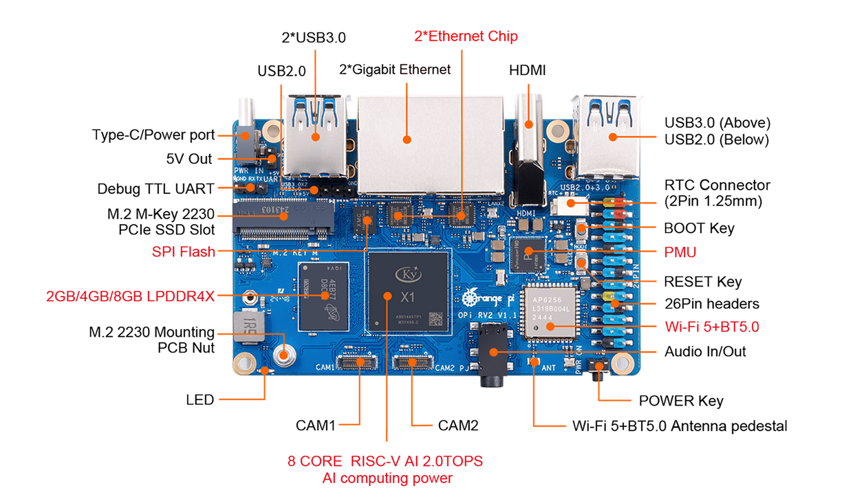
Beschriftetes Single Board Computer Modul
2*USB3.0 2*Gigabit Ethernet HDMI USB3.0 (Above) USB2.0 (Below) Type-C/Power port 5V Out Debug TTL UART RTC Connector (2Pin) M.2 M-Key 2230 PCIe SSD Slot BOOT Key SPI Flash PMU 2GB/4GB/8GB LPDDR4X RESET Key M.2 2230 Mounting 26Pin headers PCB Nut Wi-Fi 5+BT5.0 LED CAM1 CAM2 Audio In/Out CAM2 PJ ANT Wi-Fi 5+BT5.0 Antenna pedestal 8 CORE RISC-V AI 2.0TOPS AI computing power X1
in „RISC/V, überall“ · Mikrocontroller und Digitale Elektronik · · Fotos

-
Datei
atmel_beispiel.txt
PORTB #define PIN_SDO PINB #define DDR_SDO DDRB #define PORT_DATA PORTD #define PIN_DATA PIND #define DDR_DATA DDRD #define PB7 7//--\ #define PB6 6// | #define RFXX_SCK 5// | #define RFXX_SDO 4// |RF_PORT #define RFXX_SDI
in „RFM12 - Funkmodul“ · Mikrocontroller und Digitale Elektronik ·
-
PDF
UserManual_STM32H747_DISCO.pdf
VSS L3 R7 VDD VSS R3 VDD VSS +3V3 IS42S32800G-6BLI IS42S32160D-6BLI 8 5 2 1 4 1 5 9 7 5 0 7 3 4 S 3 3 1 1 2 4 4 2 3 2 3 2 2 4 SDRAM c C C C C C C C C C C C C C C h e n n n n n n n n n n n n n n m 0 0 0 0 0
in „STM32H747-DISCO0 - Demo Sourcecode gesucht“ · Mikrocontroller und Digitale Elektronik ·
-
Datei
main.c
= 0b11111111; //PORT D alle Pins als Ausgänge DDRC = 0b11111111; //PORT C alle Pins als Ausgänge DDRB = 0b11111111; //PORT B alle Pins als Ausgänge PORTD = 0b00000011; //PORT D0 und D1 auf High setzen PORTC = 0b00000000; //PORT C alle Pins auf Low setzen PORTB = 0b00000000; //PORT B alle Pins auf Low setzen while (1) { // leere Schleife } return 0; }
in „Anfänger zu den Fuse Bits“ · Mikrocontroller und Digitale Elektronik ·
-
Datei
main.c
Beeinflussung der Delay-Zeit der benutzerspezifischen Eingabespeicherung und dessen Wiedergabe DDRC = 0; // Port-C Pins als Eingänge DDRD = 0xFB; // PORT-D Pins als Ausgänge, bis auf den INT0 Interrupteingang PORTC = 0xFF; // Pullup-Widerstände für Port-C schalten GIMSK |= (1 << INT0); // generell INT0 als Interrupteingang
in „Leuchtschriftsteuerung“ · Mikrocontroller und Digitale Elektronik ·
-
Datei
problem.c
(DDB) Pin 2 (0_bit) auf Eingang +++ rechter Schleifer DDC2_bit = 0x00; //Setze Port B (DDB) Pin 3 (0_bit) auf Eingang +++ Taster SREG_I_bit = 1; // Interrupt allgemein einschalten TOIE2_bit = 1; // Timer2 overflow
in „Unterschied: IF und SWITCH Abfrage“ · Mikrocontroller und Digitale Elektronik ·
-
PDF
nucleo_F103RB_pinout_sheet.pdf
Nucleo-F103RB Pinout Sheet for Arduino IDE left right Arduino Port Pin Pin Port Arduino Arduino Port Pin Pin Port Arduino TX2 D22 PC10 1 2 PC11 D30 RX2 D32 PC9 1 2 PC8 D33 D23 PC12 3 4 PD2 D31 T4 D15 PB8 3 4 PC6 D34 VDD 5 6 E5V T4 D14 PB9 5 6 PC5 D35 15 Boot0 7 8 GND
in „Nucleo STM32-F103RB nun wirklich "Arduino kompatibel"“ · Mikrocontroller und Digitale Elektronik ·
-
PDF
Driver_Library_user_guide.pdf
family; this will determine which are present on this device. The ulPin argument must be only one of the following vaSYSCTL_PIN_PWM0, SYSCTL_PIN_PWM1, SYSCTL_PIN_PWM2, SYSCTL_PIN_PWM3, SYSCTL_PIN_PWM4, SYSCTL_PIN_PWM5, SYSCTL_PIN_C0MINUS, SYSCTL_PIN_C0PLUS, SYSCTL_PIN_C0O, SYSCTL_PIN_C1MINUS, SYSCTL_PIN_C1PLUS, SYSCTL_PIN_C1O, SYSCTL_PIN_C2MINUS, SYSCTL_PIN_C2PLUS, SYSCTL_PIN_C2O, October 30, 2008 217 System Control SYSCTL_PIN_ADC0, SYSCTL_PIN_ADC1, SYSCTL_PIN_ADC2, SYSCTL_PIN_ADC3
in „I2C Display Steuern“ · Mikrocontroller und Digitale Elektronik ·
-
Datei
main.c
: Switch on peripheral clock RCC_APB2PeriphClockCmd(RCC_APB2Periph_GPIOA | RCC_APB2Periph_SPI1 | RCC_APB2Periph_AFIO, ENABLE); // SCK and MISO are Output, AF floating (PP) as Master GPIO_InitStructure.GPIO_Pin = GPIO_Pin_5 | GPIO_Pin_7;
in „SPI-RAM-Bank an STM32F0-Discovery - write, kein read“ · Mikrocontroller und Digitale Elektronik ·
-
PDF
cp2108-datasheet-1509353.pdf
bps) 208,900 (bps) 234,000 (bps) 288,200 (bps) silabs.com | Building a more connected world. Rev. 1.2 | 11 CP2108 Data Sheet Pin Definitions 4. Pin Definitions T I E S G 0 0 0 0 0 E - + B R S D X X T T T S C I X R D D V V V V T R R C D D D R T 4 3 2 1 0 9 8 7 6 5 4 3 2 1 0 9 6 6 6 6 6 5 5 5 5 5 5 5 5 5 5 4 RX3 1 48 RX1 VSSHD 2 47 RTS1 VIOHD 3 46 CTS1 TX3 4 45 DTR1 CTS3 5 44 DSR1 RTS3 6 43 DCD1 RI3 7 42 RI1 DCD3 8 41 GPIO.0 64 pin QFN DSR3 9 (TopView) 40 GPIO.1 DTR3 10 39 VIO RI2 11 38 GPIO.2 DCD2 12
in „[V] 4St. Silabs 4-fach UART Bridge CP2108-GM (QFN64) (12€)“ · Markt ·