-
PDF
Webserver1.pdf
JP2_22 D6 JP1_16 A6 D6 JP2_21 A7 JP1_15 A7 D7 D7 A8 A8 A9 JP1_14 A9 COL_LED JP2_6 COL_LED A10 JP1_11 A10 TX_LED JP2_8 TX_LED A11 JP1_12 A11_MISO RX_LED JP2_10 RX_LED A12 JP1_9 A12_MOSI LINK_LED JP2_12 LI_LED
in „WIZ810 (WIZ5100) an XMEM Interface (AVR)“ · Mikrocontroller und Digitale Elektronik ·
-
Datei
txtext.asm
: cpi RX, 12 ;Clear all brne com12 ldi YL, low(DDRAM) ldi YH, high(DDRAM) ldi temp, 32 ldi temp2, high(XSize*YSize+DDRAM) clrloop2: st Y+, temp cpi YL, low(XSize*YSize+DDRAM) cpc YH, temp2 brne clrloop2 ldi YL
in „AVR Videogenerator, 40x25 Zeichen, nur 60% CPU Auslastung !“ · Projekte & Code ·
-
Datei
grab32.py
), 'RLA_Ventil': ('b', 2,3), 'Pumpe_Boiler': ('b',2,5), 'Pumpe_Puffer': ('b',2,7), 'Keine_Stoerung': ('b',3,0), 'Zuendung': ('b', 3,2), 'Drehrost': ('b',3,6), 'Reinigung': ('b',3,7), 'Raumaustragung_Saugturbine': ('b',4,1
-
PDF
SARA-G3_DataSheet__UBX-13000993_.pdf
) SARA-G350-01B GSM Connected Mode All 850, 1 Tx + 1 Rx slot (voice or data call 200 250 mA (Call enabled) 900 up to 21.4 kb/s UL, 21.4 kb/s DL) Maximum Tx power (32.2 dBm typ.) 1800, 1 Tx + 1 Rx slot (voice or data
in „GSM-Modul (SIM908) nur analoge Ausgänge für Anruf?“ · HF, Funk und Felder ·
-
Datei
main.c
Korrekturfaktor genau 9606bps UCTL0 &= ~SWRST; // USART freigeben IE1|= URXIE0 + UTXIE0; // TX- und RX-interrupts anschalten IFG1 &= ~UTXIFG0; // Initales interrupt-flag loeschen } void init_uart_1(void) { WDTCTL = WDTPW + WDTHOLD; // Watchdog aus P3SEL |= 0xC0; // P3.6 und 3.7 als USART1 TXD/RXD ME2
in „MSP430 GPS-Daten von UART0 Probleme“ · Mikrocontroller und Digitale Elektronik ·
-
Datei
code.txt
3 (USART RX) */ NVIC_InitStructure.NVIC_IRQChannel = DMA1_Channel3_IRQn; NVIC_InitStructure.NVIC_IRQChannelPreemptionPriority = 2; NVIC_InitStructure.NVIC_IRQChannelSubPriority = 0; NVIC_InitStructure.NVIC_IRQChannelCmd
in „USART Remapping“ · Mikrocontroller und Digitale Elektronik ·
-
Datei
Bootlog_VIP1710_mit_Soft.TXT
: USB hub found hub.c: 2 ports detected insmod: /lib/modules/2.4.30: No such file or directory Using /lib/modules/12ehci-hcd.o ehci_hcd 00:11.2: PCI device 1033:00e0 ehci_hcd 00:11.2: irq 35, pci mem b0002000 usb.c: new USB
in „Pollin MOTOROLA VIP1710“ · Mikrocontroller und Digitale Elektronik ·
-
Datei
dds-pll.asm
mode (3), positive pwm ldi tmp,128 out ocr0b,tmp ldi tmp, (1<<com0b1) + 0* (1<<com0b0) + (1<< wgm00) + (1<< wgm01) out tccr0a,tmp ldi tmp,1 ; max clock out tccr0B,tmp ; set Table for sinewave output ldi r31,high(2*sine) ; setup Z pointer hi ldi
in „PLL mit Atmega8 läuft + Fragen!“ · Mikrocontroller und Digitale Elektronik ·
-
Datei
main.c
-------- // SPI support functions void chip_select(int RAM_bank) { switch (RAM_bank) { case 0: // 0b000 GPIOA->BRR |= (GPIO_Pin_2 | GPIO_Pin_1 | GPIO_Pin_0); break; case 1: // 0b001 GPIOA->BRR |= (GPIO_Pin_2 | GPIO_Pin_1); GPIOA->BSRR |= (GPIO_Pin_0); break; case 2: // 0b010 GPIOA->BRR |= (GPIO_Pin_2 | GPIO_Pin_0); GPIOA->BSRR |= (GPIO_Pin_1); break; case 3: // 0b011 GPIOA->BRR |= (GPIO_Pin_2); GPIOA->BSRR |= (GPIO_Pin_1 | GPIO_Pin_0); break; case 4: // 0b100 GPIOA->BRR |= (GPIO_Pin_1 | GPIO_Pin_
in „OV7670 an STM32F102“ · Mikrocontroller und Digitale Elektronik ·
-
Datei
main.c
esp_system.h" #include "driver/gpio.h" #include "driver/uart.h" #define UART_NUM UART_NUM_1 #define UART_RX_GPIO GPIO_NUM_4 #define LIN_BAUDRATE 9600 static const char *TAG = "LIN_SNIFFER"; // Setup UART buffered IO with event queue const int uart_buffer_size = (1024 * 2); QueueHandle_t uart_queue; void uart_event_task
in „TJA1020 mit ESP32 betreiben“ · Mikrocontroller und Digitale Elektronik ·
-
PDF
esp_wroom_32_datasheet_en.pdf
IO6 SD_CMD IO11 SDIO interface that conforms to the SDIO Slave SD_DATA0 IO7 industry standard SDIO 2.0 card SD_DATA1 IO8 specification. SD_DATA2 IO9 SD_DATA3 IO10 EMAC_TX_CLK IO0 EMAC_RX_CLK IO5 EMAC_TX_EN IO21 EMAC_TXD0 IO19 EMAC_TXD1 IO22 EMAC_TXD2 IO14 EMAC_TXD3 IO12 EMAC_RX_ER IO13 EMAC_RX_DV IO27
-
Datei
RX_01.c
include "usart.h" #include "rf22.h" #include <328/MK3_328_V24.h> #include <util/delay.h> unsigned char rx_tmp[20]; unsigned int b=110; unsigned char cnt; ISR( INT0_vect ) { PORTB|=(1<<PB0); cnt = rf22_getpacket(rx_tmp); if (cnt!= 0) { for (unsigned char a = 0;a<cnt;a++) { usart_write_char(rx_tmp[a]); if
in „RFM22B Interrupt Empfang“ · Mikrocontroller und Digitale Elektronik ·
-
Datei
nRF24L01_Testreceiver.c
/* * nRF24L01_Testempfänger.c * * Created: 06/13/2016 16:53:10 * Author: thobe PB0: CE PB1: CSN PB2: SSnot PB3: MOSI PB4: MISO PB5: SCK PB6: XTAL PB7: XTAL PC0: PC1: PC2: PC3: PC4: PC5: RESETnot: 3,3V PD0: PD1: PD2: PD3: PD4: PD5: PD6: PD7: IRQ (PCint23) */ #ifndef F_CPU //Define F_CPU if not done
in „NRF24L01 und Atmega328P“ · Mikrocontroller und Digitale Elektronik ·
-
PDF
XPort_reference_design_and_guidelines.pdf
21SRC/TR8 1 D9 LED, Bicolor, Green/Red, 1210 SMD Lite-On --- 1 D11 Diode, 3A, 30V, SMB Diodes, Inc. B330B-13 1 J1 Power Jack, 2.5mm Pin, R/A CUI PJ-002B 1 J2 Modular Jack, RJ-11 Corcom/Tyco Elect. RJ11-6N-B 1 JP1 Header, Male, 10 Pos, .1 TH" Amp/Tyco 103240-5 4 P1,P2,P3,P4 Mounting Pad N/A N/A 3 PB1,
in „Lantronix X-Port beschalten“ · Mikrocontroller und Digitale Elektronik ·
-
PDF
specification_CA10089.pdf
Conditions ・・・・・・・・・ 11 7. Characteristics 7.1 DC Characteristics 7.1.1 Display Module ・・・・・・・・・ 12 7.1.2 MIPI DSI Interface ・・・・・・・・・ 12 7.1.3 Backlight ・・・・・・・・・ 13 7.2 AC Characteristics 7.2.1 HS-RX Specifications ・・・・・・・・・ 14 7.2.2 LP-TX Specifications ・・・・・・・・・ 14 7.2.3 RX/TX Specifications ・・・・・・・・・
in „Suche 4.3" Display mit Controller fuer DVI to RGB TTL/MIPI DSI“ · Mikrocontroller und Digitale Elektronik ·
-
PDF
DATA_Sheet_TINY_Tiger_Module_V002_en.pdf
( . R D l l l l r / / / / / / products as: C a / G n n n n C s l 7 6 5 4 3 5 4 3 2 1 0 i V B A A A A A A P r A L L L L L L L L L L L t s GPS systems + traffic control s Medical instruments 4 4 4 4 4 3 3 3 3 3 3 3 3 3 3 2 2 2 2 2 2 2 2 1 0 9 8 7 6 5 4 3 a s Security applications + access
in „geeigneter Transistor zur Schrittmotor/Treiberansteuerung über Puls/Richtungssignal mit MC“ · Analoge Elektronik und Schaltungstechnik ·
-
Datei
simple_tx.c
must //! review these and change as needed for your own board: //! - CAN0 peripheral //! - GPIO Port B peripheral (for CAN0 pins) //! - CAN0RX - PB4 //! - CAN0TX - PB5 //! //! The following UART signals are configured only for displaying console //! messages for this example. These are not required for
in „CAN-Bus mit TM4C123G und MCP2562“ · Mikrocontroller und Digitale Elektronik ·
-
PDF
SR5001_RS232_Control_Spec_MAI_V100.pdf
Host starts a data transmission fromTxD. 2. Host performs the data transmission of the number of required bytes, and ends a transmission. 3-1-1-2. Data transmission sequence from Slave to Host Host (Controller) Slave (The product) TxD → RxD RxD
in „Marantz Receiver RS232C - Protokoll“ · Mikrocontroller und Digitale Elektronik ·
-
PDF
EMS_PIC.pdf
68pF 4 R1 C 1 1 R7 EMS_232_RX 2 36 C7 C8 U1P A D8 5 A 10K 2 4k7 ACM3225 DC/DC CONVERTER L2 D B R 2 LM393D VA-0505S 2 S BAT54S 9 R m 3 4 5 GND V D 3 O R R R G D K 0 k _ G D 4 1 1 1 2 SJ2 U1 M _ S D6 1 8 1 L5 4 JP2 E M 4 EMS_GND 2
in „Buderus EMS-"Gateway" mit PIC18F / Sammelbestellung“ · Haus & Smart Home ·
-
PDF
Platine_4_Kanal.pdf
Verbraucher) o Alternativ auch P-FET für Verbraucher o Alternativ Steckverbinder für ext. Relais, z.B kompatibel zu https://www.aliexpress.com/item/5V-2-Channel-Relay-Module-for-Arduino-PIC-ARM- DSP-AVR-Electronic-Raspberry-pi/32385866986.html o Anzeige • LED für Output ein o Rückkanal vom Verbraucher
in „Hutschienen Arduino“ · Mikrocontroller und Digitale Elektronik ·
-
PDF
test.pdf
exhaustive; on some pins, more peripherals are available than are listed here. Pin GPIO ADC Timer I2C UART SPI 5 V? D0 PB11 2_SDA 3_RX Yes D1 PB10 2_SCL 3_TX Yes D2 PB2 Yes D3 PB0 CH8 3_CH3 D4 PA7 CH7 3_CH2 1_MOSI D5 PA6 CH6 3_CH1 1_MISO D6 PA5 CH5 1_SCK D7 PA4 CH4 2_CK 1_NSS D8 PA3 CH3 2_CH4 2_RX 3
in „Wie kann ich diese Webseite ausdrucken?“ · PC Hard- und Software ·
-
Datei
eeprom-debug.txt
(rx_chars() < 2) { wait(10); } // Und einlesen: mtmp = (unsigned short)uart_getc(); tmp = uart_getc(); // mtmp ==> Speicherposition, tmp ==> Byte zum schreiben/lesen // Debug-Meldung uart_puts(" Writing
in „[AVR] ATmega16 startet neu bei EEPROM-Zugriff auf 0x1F0?“ · Mikrocontroller und Digitale Elektronik ·
-
PDF
CS6422_F1.pdf
ORDERING INFORMATION See page 48. o o CS6422-IS -40 to 85 C 20-pin SOIC CDB6422 Evaluation Board NC1 NC2 NC3 NC4 DVDD AVDD 9 10 11 12 16 1 RGain RVol NI 17 ADC + Σ Rx DAC 3 AO + Suppression - 14 (0, 6, 9.5, 12 dB) (Mute, -12 to +30 dB) Pre-emphasis Clock CLKI Network Filter Generation 13 Echo Acoustic CLKO
in „Schaltung um Echo rauszufiltern“ · Mikrocontroller und Digitale Elektronik ·
-
Datei
24Receiver.c
int ubrr) { // set baud rate UBRR0H = (uint8_t) (ubrr >> 8); UBRR0L = (uint8_t) (ubrr); // activate Rx and Tx UCSR0B = /*(1<<RXEN0) | (1<<RXCIE0) | */(1<<TXEN0); // select async 8N1 UCSR0C = (3<<UCSZ00); } void uart_putchar(char c) { while (!(UCSR0A & (1 << UDRE0))); // wait for buffer ready UDR0 = c;
in „NRF24L01 und Atmega328P“ · Mikrocontroller und Digitale Elektronik ·
-
PDF
ug1091-carrier-card-design.pdf
REFCLK1 input, bank 505 B51 GND Ground, connect to carrier card ground plane B52 GND Ground, connect to carrier card ground plane B53 GTR_DP2_C2M_P PS-GTR lane 2 RX, bank 505 B54 GTR_DP2_C2M_N PS-GTR lane 2 RX, bank 505 B55 GND
-
PDF
TTester_096k.pdf
, B=9, 613mV NPN, B=9, 621mV NPN, B=9, 615mV 2N3055 NPN, B=21, 617mV NPN, B=21, 626mV NPN, B=21, 625mV BC546B NPN, B=381, 780mV NPN, B=376, 777mV NPN, B=387, 771mV BC556B PNP, B=266, 790mV PNP, B=429, 787mV
-
Datei
code.txt
3 (USART RX) */ NVIC_InitStructure.NVIC_IRQChannel = DMA1_Channel3_IRQn; NVIC_InitStructure.NVIC_IRQChannelPreemptionPriority = 2; NVIC_InitStructure.NVIC_IRQChannelSubPriority = 0; NVIC_InitStructure.NVIC_IRQChannelCmd
in „STM32 Tutorial“ · Mikrocontroller und Digitale Elektronik ·
-
Datei
code.c
3 (USART RX) */ NVIC_InitStructure.NVIC_IRQChannel = DMA1_Channel3_IRQn; NVIC_InitStructure.NVIC_IRQChannelPreemptionPriority = 2; NVIC_InitStructure.NVIC_IRQChannelSubPriority = 0; NVIC_InitStructure.NVIC_IRQChannelCmd
in „STM32 Tutorial“ · Mikrocontroller und Digitale Elektronik ·
-
Datei
main.c
1 T2CONbits.TMR2ON = 1; //Timer2 starten //Periodendauer einstellen PR2 = 156; //156 etspricht 100Hz //Pulsweite einstellen (50%), CCPR1L:CCP1CON(DC1B) = 0x138 CCPR1L = (0x0138 >> 2); //die unteren 2 Bits entfernen CCP1CONbits.DC1B = (0x0138 & 0x3); //die unteren 2 Bits rausmaskieren } void initTimer1(void) { //Timer1 control register T1CON = 0x00; //alles zurücksetzen T1CONbits.TMR1CS = 0x00; //Timer1 läuft vom Instructionclock
in „PIC16F1825 will nicht so, wie ich will“ · Mikrocontroller und Digitale Elektronik ·
-
PDF
EMS_PIC.pdf
U1P A 4700µH D8 5 A 10K C 1 2 4k7 EMS_232_RX DC/DC CONVERTER L2 D B R 2 LM393D VA-0505S 2 S 9 R K 3 4 5 V DBAT54S 3 4 1 0 R N D 1 SJ2 U1 _ N 1 2 S _ EMS_GND JP2 E S 1 VDD1 VDD2 8 1 TXD CANH 7 1 E D 6 RB2 2 VOA VIA 7 2 MEMS_GND RB3
in „Buderus EMS-"Gateway" mit PIC18F / Sammelbestellung“ · Haus & Smart Home ·
-
PDF
TTester_096k.pdf
, B=9, 613mV NPN, B=9, 621mV NPN, B=9, 615mV 2N3055 NPN, B=21, 617mV NPN, B=21, 626mV NPN, B=21, 625mV BC546B NPN, B=381, 780mV NPN, B=376, 777mV NPN, B=387, 771mV BC556B PNP, B=266, 790mV PNP, B=429, 787mV
-
Datei
startup_stm32f10x_hd.c
void WEAK DMA1_Channel6_IRQHandler(void); void WEAK DMA1_Channel7_IRQHandler(void); void WEAK ADC1_2_IRQHandler(void); void WEAK USB_HP_CAN1_TX_IRQHandler(void); void WEAK USB_LP_CAN1_RX0_IRQHandler(void); void WEAK CAN1_RX1_IRQHandler(void); void WEAK CAN1_SCE_IRQHandler(void); void WEAK EXTI9_5_IRQHandler
in „STM32F10x mit Eclipse, yagarto (GCC) und J-Link (GDB)“ · Mikrocontroller und Digitale Elektronik ·
-
PDF
ATxMega_128_Stick.pdf
Steckbrett mini USB Port Bootloaderfähig über USB microSD Karten Slot für bis zu 8 GB 192kB Flash, 2kB EEPROM, 16kB RAM sehr schnelle Berechnungen dank 32 MHz 3x SPI, 3x USART, 2x I2C 8x ADC, 2x DAC integrierter Spannungswandler Stromzufuhr über USB oder externes Netzteil alle wichtigen
in „ATxMega Stick“ · Markt ·
-
Datei
main.c
TIM_TimeBaseStructure.TIM_Period = 65535; TIM_TimeBaseStructure.TIM_ClockDivision = 0; TIM_TimeBaseInit(TIM2, &TIM_TimeBaseStructure); TIM_ClearITPendingBit(TIM2, TIM_IT_Update); //Interrupt Flag von TIM2 löschen TIM_ITConfig(TIM2, TIM_IT_Update, ENABLE); //Interrupt für TIM2 Aktivieren TIM_Cmd(TIM2, ENABLE
in „Stm32: Übertragungsfehler bei dauerhafter Übertragung“ · Mikrocontroller und Digitale Elektronik ·
-
Datei
main.lss.txt
(ispTransmit == ispTransmit_hw) { 2a6: 80 91 79 00 lds r24, 0x0079 2aa: 90 91 7a 00 lds r25, 0x007A 2ae: 20 e0 ldi r18, 0x00 ; 0 2b0: 83 36 cpi r24, 0x63 ; 99 2b2: 92 07 cpc r25, r18 2b4: 09 f4 brne .+2 ; 0x2b8 <ispEnterProgrammingMode
in „2 Programme in einem AVR“ · Mikrocontroller und Digitale Elektronik ·
-
PDF
mc68hc11a1.pdf
E ROM O P A5/D5 PC5 D A D P A4/D4 PC4 T D H D SCI TxD PD1 A3/D3 PC3 R T A RxD PD0 P O A2/D2 PC2 P A1/D1 PC1 A0/D0 PC0 R/W STRB AS STRA PARALLEL I/O EQUIVALENT TO MC68HC24 Figure 1 MC68HC11A8 Block Diagram MOTOROLA MC68HC11A8 4 MC68HC11A8TS/D B W I S L / / / / N N N N T R R D
in „mc68hc11a1fn-uC-8bit“ · Markt ·
-
Datei
MJoy.asm
pin pull-up 1.5kOhm .equ USBpinmask =0b11111100 ;mask low 2 bit (D+,D-) on PB .equ USBpinmaskDplus =~(1<<DATAplus) ;mask D+ bit on PB .equ USBpinmaskDminus =~(1<<DATAminus);mask D- bit on PB .equ SOPbyte =0b10000000 ;Start of Packet byte .
in „IGOR USB lässt sich nicht assemblieren“ · Mikrocontroller und Digitale Elektronik ·
-
Datei
code.c.txt
kHz erzeugen //UBR11 = 0x00; // siehe application note tabelle 2, seite 10 //UMCTL1 = 0x29; //0x4A; // korrektur der division UBR01=0x1B; UBR11=0x00; UMCTL1=0x94; /* uart1 32768Hz 12 00bps (1200.29bps) */ UCTL1 &= ~SWRST; // USART freigeben printf("starting\n"); IE2 |= URXIE1;// + UTXIE1; // TX- und RX-interrupts anschalten IFG2 &= ~UTXIFG1; // initales interrupt-flag loeschen _BIS_SR(/*LPM3_bits + */GIE); // ab in den LPM3 mit interrupts ... for(;;); } #pragma vector=UART1TX_VECTOR __interrupt void
in „MSP430 UART Interrupt wird nicht ausgelöst“ · Mikrocontroller und Digitale Elektronik ·
-
PDF
manual_maestro.pdf
when the UART’s internal buffer fills up. This should not occur during normal operation. • Serial RX buffer full (bit 2) A firmware-level error that occurs when the firmware’s buffer for bytes received on the RX line is full and a byte from RX has been lost as a result. This error should not occur during
in „Pegelwandler 3.3v -> 5v“ · Mikrocontroller und Digitale Elektronik ·
-
Datei
avrwsr_Tiny_Nobby.asm
2002.08.09 ; Target: AT90S2313 ; ;----------------------------------------------------------------- ; ; ; RX/TX: MAX232 ; INT0 and INT1: AM-UHF-433MHz-Receiver ; ; ; Copyright (C) 2002 Thomas Fischl <fischl@FundF.net> ; modified by Nobby: RS-232 Datenformat 8 Datenbit, odd parity, 2 stopbits ; ; This
in „AM Funkmodul dekodieren“ · Mikrocontroller und Digitale Elektronik ·
-
PDF
GPS_Datenlogger.pdf
GROUPID=2953;ARTICLE=45597;START=0; 1,55 1,55 24C512 SORT=artnr;OFFSET=16;SID=25zSNJXKwQARkAAHEBuWw9b0aecb77a2c64fc8e5032d84d824160 1 LCD-Modul http://www.pollin.de/shop/shop.php?cf=detail.php&pg=NQ==&a=NDU0OTc4OTk= 1,95 1,95 1 Punktrasterplatine http://www.pollin.de/shop/shop.php?cf=detail.php&pg=NQ
in „GPS Datenlogger Eigenbau Montageanleitung“ · Projekte & Code ·
-
Datei
main.asm
ready _Ret1: ret ;*********************************************************** RunTimer2: ;reset menu after 60 seconds lds temp1, Timer2 lds temp2, Time2 inc temp1 sts Timer2, temp1 cp temp1, temp2 brcs _Ret2 clr temp1 sts Timer2, temp1 lds temp1, TimerFlags andi temp1, 0b11111011 ;clear
-
PDF
TMC5240-EVAL_V10_-_Schematic_Drawing.pdf
GND GND GND GND 6 27 28 C207 POK NC C208 NC NC 1uF/16V GND 4.7uF/6.3V 25 26 0603 0603 NC NC 2 MAX8881EUT33 23 24 SOT23-6 CLK NC 21 22 UART_TX DIAG1/UART_RX Motor Connector GND GND GND 19 20 SLEEP UART_EN 17 18 REFL_INT REFR_INT 15 16 NC NC J203 EEPROM 13 14 1 NC NC B1 4 4 NC 11 12 NC 2 B2 +VCC_IO
in „TMC5240 antwortet nicht im Single Wire Uart“ · Mikrocontroller und Digitale Elektronik ·
-
Datei
rf12.c
(); rf12_trans(0xB8AA); rf12_ready(); rf12_trans(0xB8AA); rf12_trans(0x8209); // TX off } uint8_t rf12_rec(void) { uint16_t fifo_data; while(PINC&(1<<PC2)); rf12_trans(0x0000); fifo_data = rf12_trans(0xB000); return (fifo_data
in „RFM12 Empfäng: MSB = 1, Rest = Daten + Resetproblem“ · Mikrocontroller und Digitale Elektronik ·
-
PDF
6neds.pdf
TAiOUT Pulse output (i = 0 to 4) Toggle flip-flop Note: The TA0 IN pin (P71) is shared with TB5 IN, RxD 2 and SCL pin, so to be careful. Figure 1.14.3. Block diagram of timer A Timer Ai mode register Symbol Address When reset b7 b6 b5 b4 b3 b2 b1 b0 TAiMR(i=0 to 4) 0396 16 to 039A 16 00 16 R W Bit symbol
in „M16C- Key Input Interrupt“ · Mikrocontroller und Digitale Elektronik ·
-
 Bild
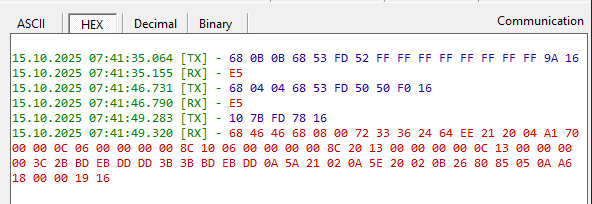
Hexadezimaler Log-Auszug einer seriellen Kommunikation
ASCII HEX Decimal Binary Communication 15.10.2025 07:41:35.064 [TX] - 68 0B 0B 68 53 FD 52 FF FF FF 9A 16 15.10.2025 07:41:35.155 [RX] - E5 15.10.2025 07:41:46.731 [TX] - 68 04 04 68 53 FD 50 50 F0 16 15.10.2025 07:41:46.790 [RX] - E5 15.10.2025 07:41:49.283 [TX] - 10 7B FD 78 16 15.10.2025 07:41:49.320 [RX] - 68 46 46 68 08 00 00 72 33 36 24 64 EE 21 20 04 A1 70 00 00 0C 06 00 00 00 8C 10 06 00 00 00 8C 20 13 00 00 00 0C 13 00 00 00 3C 2B BD EB DD D3 3B BD 3B BD EB DD 0A 5A 21 02 0A 5E 20 02 0B 26 80 85
in „Sharky 773 mit intereme M-Bus auslesen“ · Haus & Smart Home · · Screenshots

-
Datei
code.txt
6 (USART RX) */ NVIC_InitStructure.NVIC_IRQChannel = DMA1_Channel6_IRQn; NVIC_InitStructure.NVIC_IRQChannelPreemptionPriority = 2; NVIC_InitStructure.NVIC_IRQChannelSubPriority = 0; NVIC_InitStructure.NVIC_IRQChannelCmd
in „USART Remapping“ · Mikrocontroller und Digitale Elektronik ·
-
PDF
arduino-leonardo-schematic_3b.pdf
)PD3 21 D1/TX D6* 6# #PWM Hi-Speed +A8 UGND 5 UGND (RXD1/AIN1/INT2)PD2 20 D0/RX UGND 5 UGND (RXD1/AIN1/INT2)PD2 20 D0/RX D5* 5# #PWM Hi-Speed 7 VBUS (SDA/INT1)PD1 19 D2/SDA VUSB 7 VBUS (SDA/INT1)PD1 19 D2/SDA D4 4 +A6 VUSB (OC0B/SCL/INT0)PD0 18 D3/SCL (OC0B/SCL/INT0
in „externe Speisung eines Arduino Leonardo“ · Mikrocontroller und Digitale Elektronik ·
-
PDF
XPort-Pro_IG.pdf
B EN55022:2006 and EN55024:1998 + A1:2001 + A2:2003 AS/NZS CISPR22:2006 VCCI V-3/2009.04 EN61000-3-2:2006, EN 61000-3-3:1995+A1:2001+A2:2005 EN61000-4-2 (+/-4kV Contact Discharge, +/-8kV Air
in „[V] 2St. gebrauchte Lantronix XPORT PRO Module -LAN-Seriell, KLEINEN DEFKTEN , zu Fädeln (beide 8€)“ · Markt ·