-
PDF
readme_151223.pdf
integrierter DALI-Schnittstelle. Damit habe ich gearbeitet. Das Projekt besteht aus 2 Teilen: Der Hardware (ATTiny2313), programmiert in C und einem User-Interface, realisiert mit Python / TKinter. 1.) Hardware + C-Programm EinATTiny2313 fungiert als Gateway zwischen serieller Schnittstelle und dem DALI-Bus. Der
in „RS232-DALI-Gateway für ATtiny2313 / Python-GUI“ · Projekte & Code ·
-
Datei
USI_TWI_Master.h
is written for the ATmega169, ATtiny26 and ATtiny2313 * * AppNote : AVR310 - Using the USI module as a TWI Master * * Description : This is an implementation of an TWI master using * the USI module as basis. The implementation assumes
in „Butterfly USI als TWI Master verwenden“ · Mikrocontroller und Digitale Elektronik ·
-
Datei
main.c
irsnd.h" #ifndef F_CPU # error F_CPU unknown #endif void timer1_init (void) { #if defined (__AVR_ATtiny45__) || defined (__AVR_ATtiny85__) // ATtiny45 / ATtiny85: OCR1C = (F_CPU / F_INTERRUPTS / 4) - 1; // compare value: 1/15000 of CPU frequency, presc = 4 TCCR1 = (1 << CTC1) | (1 << CS11) | (1 << CS10
in „IRSND Daten für Roomba“ · Mikrocontroller und Digitale Elektronik ·
-
Datei
attiny2313.c
/******************************************************* Projekt: DP Lüftersteuerung Version : ATTiny2313A - 1 Erstellt: 22.10.2016 Letze Änderung: 24.10.2016 Chip: Attiny2313A mit internen 8.0 MHz *******************************************************/ /// Header-Dateien /// #include <io.h> #include
in „Attiny2313A - Timer Interrupt wird nicht aufgerufen (C)“ · Mikrocontroller und Digitale Elektronik ·
-
Datei
AVRStrudio4.11b401_Release_Notes.txt
causes unstable operation when placing a breakpoint on line 65535 of an Assembler project SIMULATOR * ATtiny26: various fixes for Timer/Counter1. * ATtiny15: various fixes for Timer/Counter1. * Various fixes for most devices' Timer/Counter0: is now cycle-correct and fully functional. * Fixed problem with
in „AVRStudio4 v4.11 Build 401 Beta freigegeben“ · Mikrocontroller und Digitale Elektronik ·
-
Datei
tm16xx.h
Anode und zusaetzlichem Tasteninterface. Geeignet fuer: TM1651, TM1637 MCU : alle AVR ( getestet ATtiny85, ATtiny2313, ATtiny44, ATmega8, ATmega328p ) F_CPU : 8 MHz intern Pinbelegung Controller TM16xx --------------------------- PB1 CLK PB0 DIO CLK und DIO sind mit jeweils 2,2 kOhm Pop-Up Wider- staenden
in „Siebensegment und Tasten ansteuern mit TM1651 \ TM1637“ · Projekte & Code ·
-
Datei
SPIsourceATmega.txt
-------------------------------------------------------------- fertigL: in r16,PINC ; Antwort v. ATTiny durch low-Signal auf PIN C3 sbrc r16,3 ; ATTiny fertig? rjmp fertigL ; nein clr R0 ret ;------------------------------------------------------------------------ fertigH: in r16,PINC ; Antwort v. ATTiny durch high-Signal auf PIN C3 sbrs r16,3 ; ATTiny fertig? rjmp fertigH ; nein inc R0 ret ;------------------------------------------------------------------------ ;beide Slaves stoppen SlaveStop: sbi PORTC,1 sbi PORTC,2 ret ;----------------------
in „SPI Kopplung von ATmega8 und ATtiny 2313“ · Projekte & Code ·
-
Datei
SIR.c
uart.h" #include "irmp.h" #define UART_BAUD_RATE 38400 void timer1_init (void) { #if defined (__AVR_ATtiny45__) || defined (__AVR_ATtiny85__) // ATtiny45 / ATtiny85: #if F_CPU >= 16000000L OCR1C = (F_CPU / F_INTERRUPTS / 8) - 1; // compare value: 1/15000 of CPU frequency, presc = 8 TCCR1 = (1 << CTC1) |
in „uart_puts funktioniert nur sporadisch (zusammen mit IRMP)“ · Mikrocontroller und Digitale Elektronik ·
-
PDF
Arduino.pdf
AVR_ATmega2560__) ADMUX = _BV(REFS0) | _BV(MUX4) | _BV(MUX3) | _BV(MUX2) | _BV(MUX1); #elif defined (__AVR_ATtiny24__) || defined(__AVR_ATtiny44__) || defined(__AVR_ATtiny84__) ADMUX = _BV(MUX5) | _BV(MUX0); #elif defined (__AVR_ATtiny25__) || defined(__AVR_ATtiny45__) || defined(__AVR_ATtiny85__) ADMUX = _BV(
in „Aref Spannung, was ist besser?“ · Mikrocontroller und Digitale Elektronik ·
-
Datei
main.c
include "irmp.h" #ifndef F_CPU #error F_CPU unkown #endif void timer1_init (void) { #if defined (__AVR_ATtiny45__) || defined (__AVR_ATtiny85__) // ATtiny45 / ATtiny85: #if F_CPU >= 16000000L OCR1C = (F_CPU / F_INTERRUPTS / 8) - 1; // compare value: 1/15000 of CPU frequency, presc = 8 TCCR1 = (1 << CTC1) |
in „IRMP - Infrared Multi Protocol Decoder“ · Projekte & Code ·
-
Datei
RFID-Reader-Modul.c
/* / Projektname : RFID-Reader-Modul / Dateiname : RFID-Reader-Modul.c / Version : 1.0.0 - ATtiny2313 / Datum : 28.12.2013 / Compiler : WinAVR 20100110 libc 1_7_1 / Autor : Johannes Kretzmann / Copyright : johannes.kretzmann@projektsammlung.de / www.projektsammlung.de / / / / Mikrocontroller: ATtiny2313
in „Attiny2313 eeprom Fragen“ · Mikrocontroller und Digitale Elektronik ·
-
Datei
definition_tn2313.txt
;***** THIS IS A MACHINE GENERATED FILE - DO NOT EDIT ******************** ;***** Created: 2005-01-11 10:31 ******* Source: ATtiny2313.xml ********** ;************************************************************************* ;* A P P L I C A T I O N N O T E F O R T H E A V R F A M I L Y ;* ;* Number : AVR000 ;* File Name : "tn2313def.inc" ;* Title : Register/Bit Definitions for the ATtiny2313 ;* Date : 2005-01-11 ;* Version : 2.14 ;* Support E-mail : avr@atmel.com ;* Target MCU : ATtiny2313 ;* ;* DESCRIPTION ;* When including this file in the assembly program file, all I/O register
in „Attiny2313 programmieren“ · Mikrocontroller und Digitale Elektronik ·
-
Datei
tn2313def.inc
;***** THIS IS A MACHINE GENERATED FILE - DO NOT EDIT ******************** ;***** Created: 2005-11-04 09:37 ******* Source: ATtiny2313.xml ********** ;************************************************************************* ;* A P P L I C A T I O N N O T E F O R T H E A V R F A M I L Y ;* ;* Number : AVR000 ;* File Name : "tn2313def.inc" ;* Title : Register/Bit Definitions for the ATtiny2313 ;* Date : 2005-11-04 ;* Version : 2.21 ;* Support E-mail : avr@atmel.com ;* Target MCU : ATtiny2313 ;* ;* DESCRIPTION ;* When including this file in the assembly program file, all I/O register
in „ATTINY2313 16Mhz“ · Mikrocontroller und Digitale Elektronik ·
-
Datei
Values.txt
74LS08N 12 47µ 12 4052D 12 35701331 12 27pF 12 27k 12 2,2n 12 22µ 12 1N4446 12 1,8k 12 1.2 12 10 µF 11 TOBU3 11 RS232 11 MEGA8-AI 11 IR 11 4.7u 11 4,7µ 11 39 11 33K 11 2u2 11 2N3904 11 270R 11 27 11 22k 11 2,2k 11 18,432MHz 11 15nF 11 100uF 11 0R 11 0,1 uF 10 PORT 10 AVR-ISP-6 10 8MHz 10 680 Ohm 10 4u7
in „[KiCad] Bibliotheksaufbau - Konzeptideen gesucht“ · Platinen ·
-
Datei
USI_TWI_Slave.h
module can be used. * The example is written for the ATmega169, ATtiny26 & ATtiny2313 * * AppNote : AVR312 - Using the USI module as a TWI slave * * Description : Header file for USI_TWI driver * * * ********************************************************************
in „AVR: I2C bleibt hängen“ · Mikrocontroller und Digitale Elektronik ·
-
Datei
tinytouchlib.diff
charge_transfer_time); DDRB &= ~(_BV(tt_sensepin)); // float pad input, note that pull up is off. @@ -101,10 +97,11 @@ while (!(ADCSRA&_BV(ADIF))); ADCSRA |= _BV(ADIF); // Clear ADIF + uint16_t dat1 = 0x100; #ifdef __AVR_ATtiny10__ - dat1 = ADCL; + dat1 -= ADCL; #else - dat1 = ADCH; + dat1 -= ADCH; #endif // Precharge
in „TinyTouchLib - Touchbutton library für Attiny“ · Mikrocontroller und Digitale Elektronik ·
-
PDF
stk500_ba_-2.pdf
Die Systemsoftware unterstützt zur Zeit folgende AVR’s in allen Ge- schwindigkeitsstufen (MHz): • ATtiny11 • AT90S4433 • ATtiny12 • AT90S4434 • ATtiny15 • AT90S8515 • ATtiny22 • AT90S8535 • ATtiny28 • ATmega8 • AT90S1200 • ATmega16 • AT90S2313 • ATmega161 • AT90S2323 • ATmega163 • AT90S2333 • ATmega323
in „deutsche version vom stk500 handbuch“ · Mikrocontroller und Digitale Elektronik ·
-
Datei
Fernbedienung_mit_IRSND_mega8.c
Andreas */ #define F_CPU 8000000L #include "irsnd.h" void timer1_init (void) { #if defined (__AVR_ATtiny45__) || defined (__AVR_ATtiny85__) // ATtiny45 / ATtiny85: OCR1C = (F_CPU / F_INTERRUPTS / 4) - 1; // compare value: 1/15000 of CPU frequency, presc = 4 TCCR1 = (1 << CTC1) | (1 << CS11) | (1 << CS10
in „IR Fernbedienung mit IRSND“ · Mikrocontroller und Digitale Elektronik ·
-
Datei
Fernbedienung_mit_IRSND_mega8.c
Andreas */ #define F_CPU 8000000L #include "irsnd.h" void timer1_init (void) { #if defined (__AVR_ATtiny45__) || defined (__AVR_ATtiny85__) // ATtiny45 / ATtiny85: OCR1C = (F_CPU / F_INTERRUPTS / 4) - 1; // compare value: 1/15000 of CPU frequency, presc = 4 TCCR1 = (1 << CTC1) | (1 << CS11) | (1 << CS10
in „IR Fernbedienung mit IRSND“ · Mikrocontroller und Digitale Elektronik ·
-
Datei
AVR.html
height: 20px;" class="hcp1" valign="top"> <td colspan="1" rowspan="1" style="width: 8.485%;" class="hcp11" width="8.485%"> <p class="hcp12" align="right">ATtiny9</p> </td> <td colspan="1" rowspan="1" style="width: 6.776%;" class="hcp13" width="6.776%"> <p class="hcp14" align="center"><span class="hcp15">
in „Billige Alternative zu AVR STK 500 oder Wie brenne ich günstig mein Programm auf den Mikrochip?“ · Mikrocontroller und Digitale Elektronik ·
-
Datei
IRMP_Test_nio.txt
#define F_CPU 16000000 #include "irmp.h" static void timer1_init (void) { #if defined (__AVR_ATtiny45__) || defined (__AVR_ATtiny85__) // ATtiny45 / ATtiny85: #if F_CPU >= 16000000L OCR1C = (F_CPU / F_INTERRUPTS / 8) - 1; // compare value: 1/15000 of CPU frequency, presc = 8 TCCR1 = (1 << CTC1) |
in „IR NEC Signal mit einlesen“ · Mikrocontroller und Digitale Elektronik ·
-
Datei
VirtualWire.cpp
defined #endif #include "VirtualWire.h" #include <util/crc16.h> #undef TIMER_VECTOR #ifdef __AVR_ATtiny85__ # define TIMER_VECTOR TIM0_COMPA_vect #elif defined(__AVR_ATtiny84__) || defined(__AVR_ATtiny24__) || defined(__AVR_ATtiny44__) // Why can't Atmel make consistent? # define TIMER_VECTOR TIM1_COMPA_vect
in „Korrigierte "VirtualWire" Library für Attiny84 / 85“ · Projekte & Code ·
-
Datei
txlcd_i2c_demo.c
, 0x0e, 0x0c, 0x08, 0x00 }; static const unsigned char ohmbmp[8] PROGMEM = // Ohmzeichen { 0x0e, 0x11, 0x11, 0x11, 0x0a, 0x0a, 0x1b, 0x00}; /* -------------------------------------------------------- my_putchar wird von my-printf / printf aufgerufen und hier muss eine Zeichenausgabefunktion angegeben
in „(sehr) kleines "FrameWork" für ATtiny44“ · Projekte & Code ·
-
Datei
1wire.cpp
along with this program. If not, see <http://www.gnu.org/licenses/>. // // //VERSION 1.1 DS2423 for ATTINY2313 and ATTINY25 //FOR MAKE by hand /* avr-gcc -mmcu=[attiny25|attiny2313] -O2 -c ow_slave_DS2423.c avr-gcc.exe -mmcu=[attiny25|attiny2313] ow_slave_DS2423.o -o ow_slave_DS2423.elf avr-objcopy -O ihex
in „1-Wire Slave auf AVR“ · Mikrocontroller und Digitale Elektronik ·
-
Datei
README.txt
========================================================================= Tested on this AVRs: - ATtiny 45 / 16 MHz - ATmega 168 / 20 MHz - ATxmega 192A3 / 32 MHz0 Should work on: - ATtiny 45/85 - ATmega 48/88/168/328 - ATxmega xA3(U) The operation frequency needs to be at least 16 MHz. =============
in „AVR ASM ws2811 / ws2812 Ansteuerung mit FastPWM“ · Projekte & Code ·
-
Datei
wiring.c
volatile unsigned long timer0_millis = 0; static unsigned char timer0_fract = 0; #if defined(__AVR_ATtiny24__) || defined(__AVR_ATtiny44__) || defined(__AVR_ATtiny84__) SIGNAL(TIM0_OVF_vect) #else SIGNAL(TIMER0_OVF_vect) #endif { // copy these to local variables so they can be stored in registers // (volatile
in „IRMP - Infrared Multi Protocol Decoder“ · Projekte & Code ·
-
Datei
AVR_Tiny_Bootloader.c
/* * AVR_Tiny_Bootloader.c * * Created: 11.02.2014 16:25:16 * Author: Marius Dege // pf write hexfile to flash memory // return value: pf+ // The + indicates successful interpretation of the command. // Now an intel hex file can be send to the
in „ATTiny1634 Bootloader C nimmt nicht alles korrekt an“ · Mikrocontroller und Digitale Elektronik ·
-
Datei
AVR_Tiny_Bootloader.c
/* * AVR_Tiny_Bootloader.c * * Created: 11.02.2014 16:25:16 * Author: Marius // pf write hexfile to flash memory // return value: pf+ // The + indicates successful interpretation of the command. // Now an intel hex file can be send to the MCU
in „ATtiny Bootloader C füllt FF's in Flash“ · Mikrocontroller und Digitale Elektronik ·
-
PDF
SermultiChip.pdf
Pinbelegung A HV 4 3 2 F 1 B G E C BAT D Backplane 30 29 28 27 26 25 24 23 22 21 20 19 18 17 16 15 14 13 12 11 10 09 08 07 06 05 04 03 02 01 Pinbelegung am Chip D3 E2 F2 A2 B2 C2 D2 E1 G1 F1 A1 16 17 19 20 21 22 23 24 25 26 27 B3 15 28 B1 F3 14 29 C1 E3 13 30 D1 B/C4 12 + G4 11 Back1,2,3 G3 9 A3 8 C3 7 G2 6 10
in „Multimeter mit serieller Schnittstelle für unter 10€“ · Projekte & Code ·
-
PDF
AVR042_Hardware_Design_Considerations_doc2521.pdf
target application board so that the ISP connectors can be accessed easily. Note: 1. Except the ATtiny10, ATtiny11 and ATtiny28. On most devices the ISP interface is located on the same pins as the SPI interface. However, there are exceptions from this rule, e.g. the ATmega103 and the ATmega128 do not
in „Atmega 8A PU“ · Mikrocontroller und Digitale Elektronik ·
-
Datei
iotnx61.h
/* $Id: iotnx61.h,v 1.6 2007/12/12 14:00:49 arcanum Exp $ */ /* avr/iotnx61.h - definitions for ATtiny261, ATtiny461 and ATtiny861 */ /* This file should only be included from <avr/io.h>, never directly. */ #ifndef _AVR_IO_H_ # error "Include <avr/io.h> instead of this file." #endif #ifndef _AVR_IOXXX_H
in „Fehler in ATtiny461 Definitions-Header“ · Mikrocontroller und Digitale Elektronik ·
-
PDF
Funksteckdosen-1.pdf
Zunächst schließe ich das Empfangsmodul aneine elektrische Quelle von 5 V an; dazu benutze ich meine Attiny-Platine (http://www.g-heinrichs.de/wordpress/index.php/attiny/). Die beiden Data-Ausgänge unterscheiden sich nicht in ihrerFunktion; einendavon schließe ich an Kanal 0 meines Logik-Analysators an;
in „Auseinandergenommene Geräte“ · Analoge Elektronik und Schaltungstechnik ·
-
Datei
main.c
debounce.h" #ifndef F_CPU # error F_CPU unknown #endif void timer1_init (void) { #if defined (__AVR_ATtiny45__) || defined (__AVR_ATtiny85__) // ATtiny45 / ATtiny85: OCR1C = (F_CPU / F_INTERRUPTS / 4) - 1; // compare value: 1/15000 of CPU frequency, presc = 4 TCCR1 = (1 << CTC1) | (1 << CS11) | (1 << CS10
in „Konzeption einer IR Fernbedienung“ · Mikrocontroller und Digitale Elektronik ·
-
PDF
TSL230_ReadMe_110717.pdf
Messung der Beleuchtungsstärke mit TSL230 und ATtiny2313 in C Messung der Beleuchtungsstärke mit Light-to-Frequency-Converter TSL230R und ATtiny2313 in C 1.) Allgemeines Der Light_To_Frequency-Converter TSL230 erzeugt an seinem Ausgangspin einen Takt
in „Messung der Beleuchtungsstärke mit TSL230R und ATtiny2313 in C“ · Projekte & Code ·
-
Datei
main.c
#ifndef __AVR_ATtiny2313A__ #define __AVR_ATtiny2313A__ #endif #include <avr/io.h> #include <avr/interrupt.h> #include <avr/sleep.h> #include <avr/wdt.h> //#define F_CPU 8000000UL // ATtiny2312A internal clock (CKDIV8
in „Ablufthaubensteuerung, Schaltung entstören“ · Mikrocontroller und Digitale Elektronik ·
-
Datei
tn4313def.inc
" ;* Title : Register/Bit Definitions for the ATtiny4313 ;* Date : 2010-08-20 ;* Version : 2.35 ;* Support E-mail : avr@atmel.com ;* Target MCU : ATtiny4313 ;* ;* DESCRIPTION ;* When including this file in the assembly program file, all I/O register
in „Woher kriege ich die Datei t4313def.inc?“ · Mikrocontroller und Digitale Elektronik ·
-
Datei
GccApplication3.c
/*************************************************************************************** Titel: ATtiny TPS Author: Christian Hottum File: ATtiny461A_TPS.c Version: 0.1 Datum: 09.01.2015 Software: AVR-GCC 4.3.3 Target: ATtiny461A DESCRIPTION Firmware für einen Tasten Programierbare Steuerung auf Basis einen ATtiny461A mit 3 Tasten (S1(PB0), S2(PB2) und reset(PB7)), 4 digitale Eingängen (PA0 - PA3), 2 ADC Eingänge (PB4 - PB5), 4 digitale Ausgänge (PA4 - PA7), 2 PWM Ausgänge (PB1, PB3), Freie Pins (PB6), 8 MHZ
in „AVR TTiny 461 Pullup nicht aktiv?“ · Mikrocontroller und Digitale Elektronik ·
-
Datei
GccApplication3.c
/*************************************************************************************** Titel: ATtiny TPS Author: Christian Hottum File: ATtiny461A_TPS.c Version: 0.1 Datum: 09.01.2015 Software: AVR-GCC 4.3.3 Target: ATtiny461A DESCRIPTION Firmware für einen Tasten Programierbare Steuerung auf Basis einen ATtiny461A mit 3 Tasten (S1(PB0), S2(PB2) und reset(PB7)), 4 digitale Eingängen (PA0 - PA3), 2 ADC Eingänge (PB4 - PB5), 4 digitale Ausgänge (PA4 - PA7), 2 PWM Ausgänge (PB1, PB3), Freie Pins (PB6), 8 MHZ
in „AVR TTiny 461 Pullup nicht aktiv?“ · Mikrocontroller und Digitale Elektronik ·
-
Datei
tn2313def.inc
" ;* Title : Register/Bit Definitions for the ATtiny2313 ;* Date : 2010-08-20 ;* Version : 2.35 ;* Support E-mail : avr@atmel.com ;* Target MCU : ATtiny2313 ;* ;* DESCRIPTION ;* When including this file in the assembly program file, all I/O register
in „Welche .def ist die richtige?“ · Mikrocontroller und Digitale Elektronik ·
-
Datei
tn2313def.inc
" ;* Title : Register/Bit Definitions for the ATtiny2313 ;* Date : 2005-10-01 ;* Version : 2.20 ;* Support E-mail : avr@atmel.com ;* Target MCU : ATtiny2313 ;* ;* DESCRIPTION ;* When including this file in the assembly program file, all I/O register
in „AVR000: Register and Bit-Name Definitions“ · Mikrocontroller und Digitale Elektronik ·
-
Datei
RFID_2Kanal_V3_doc1.bas
1) Found = 128 'wieder Löschen 128 für Tag nicht im EEprom Goto Zweites_pruefen End If If Found > 11 Then Set Portb.7 ' Led 2 Ein (Tag ist aus Gruppe 2) End If Else 'Tag nicht im EEprom If Modus = 2 Or Modus = 5 Then If Gruppe1_leer > 55 Then Gruppe1_leer = 55 ' 11 Transponder schon im EEprom für Gruppe
in „Pollin RFID Entwicklungsboard“ · Mikrocontroller und Digitale Elektronik ·
-
Datei
Temp.asm
clk/4= abt. 1kHz ;*************************************************************************** ; ATtiny26 Pin Assignment: ; 01 PB.0 MOSI/ CW-Tone-out ; 02 PB.1 MISO ; 03 PB.2 SCK ; 04 PB.3 OC1B MotDrive(U) ; 05 Vcc ; 06 Gnd ; 07 PB.4 AD7/RS232negVoltChgPump (T0) ; 08 PB.5 AD8 ; 09 PB.6 AD9/RS232 TxD-
in „Tiny26 Programm ändern in Programm für Mega8“ · Mikrocontroller und Digitale Elektronik ·
-
Datei
telefonadapter.c
Wählziffern // '*'=14, '#'=15, wie im EEPROM-Kurzwahlspeicher /* EEPROM-Kurzwahlspeicher (256 Bytes eines ATtiny45): 11 Blöcke { 1 Byte Nummernlänge 30 Nibbles (15 Bytes) Ziffern (wie oben kodiert; LSN zuerst) } für Wahlwiederholung (Index 0) und 10 Rufnummernspeicher 5 Blöcke à 16 Bytes = 80 Bytes sind noch
in „HEX-File passt nicht in Attiny 25“ · Mikrocontroller und Digitale Elektronik ·
-
Datei
wiring.c
volatile unsigned long timer0_millis = 0; static unsigned char timer0_fract = 0; #if defined(__AVR_ATtiny24__) || defined(__AVR_ATtiny44__) || defined(__AVR_ATtiny84__) SIGNAL(TIM0_OVF_vect) #else SIGNAL(TIMER0_OVF_vect) #endif { // copy these to local variables so they can be stored in registers // (volatile
in „IRMP - Infrared Multi Protocol Decoder“ · Projekte & Code ·
-
Datei
vali_rc5.c
_COMP_vect #endif /* defined(__AVR_ATmega32__) */ /*****************************/ /**** TARGET = ATTINY2313 ****/ /*****************************/ #if defined(__AVR_ATtiny2313__) #define DISABLE_INT0() do { \ GIMSK &= ~(1<<INT0); \ } while(0) #define ENABLE_INT0() do { \ EIFR |= (1<<INTF0); \ GIMSK |=
in „Atmega 32 RC5“ · Mikrocontroller und Digitale Elektronik ·
-
 Bild
Bild
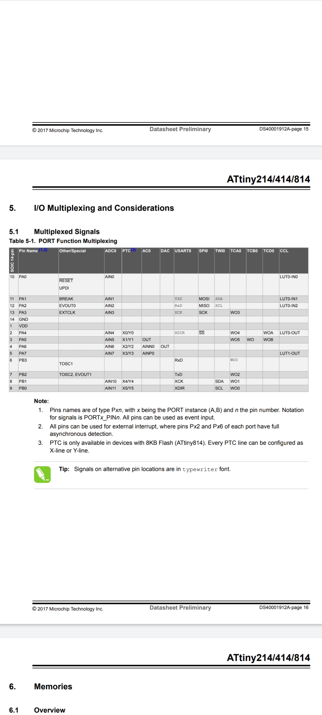
Datenblatt ATtiny214/414/814 I/O Multiplexing Tabelle
ATtiny214/414/814 5. I/O Multiplexing and Considerations 5.1 Multiplexed Signals Table 5-1. PORT Function Multiplexing Pin Name Other/Special ADC0 PTC A0 DAC USART0 SPI TC0 TCA TCBO TCDO CCL 10 PA0 RESET
in „Clock-Output beim ATtiny814“ · Mikrocontroller und Digitale Elektronik · · Screenshots
-
 Bild
Bild
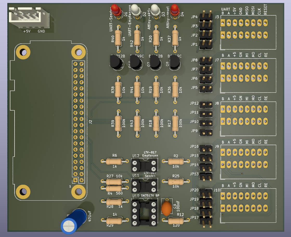
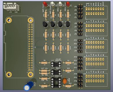
CAD-Ansicht eines Leiterplatten-Layouts
+5V GND UART-Sende D1 UART-Empfang D2 Attiny-aktiv D3 Attiny-reset D4 JP4 JP3 J3 B A +5V GND MOSI CLK RESET R40 1k R42 1k JP2 JP1 R37 1k 12B 49C 2B B 9C JP8 J7 B A +5V GND MOSI CLK RE R38 10k R41 10k R19 10k R36 10k JP5 JP12 JP11 J8 B A +5V GND
in „BME280 mit Attiny85 auslesen Daten per SN75176 an Pi senden“ · Mikrocontroller und Digitale Elektronik · · Layouts
-
 Bild
Bild
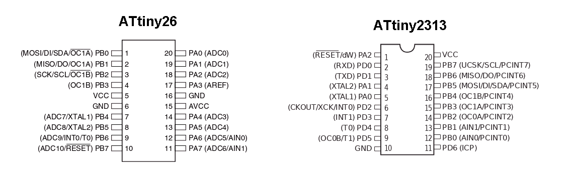
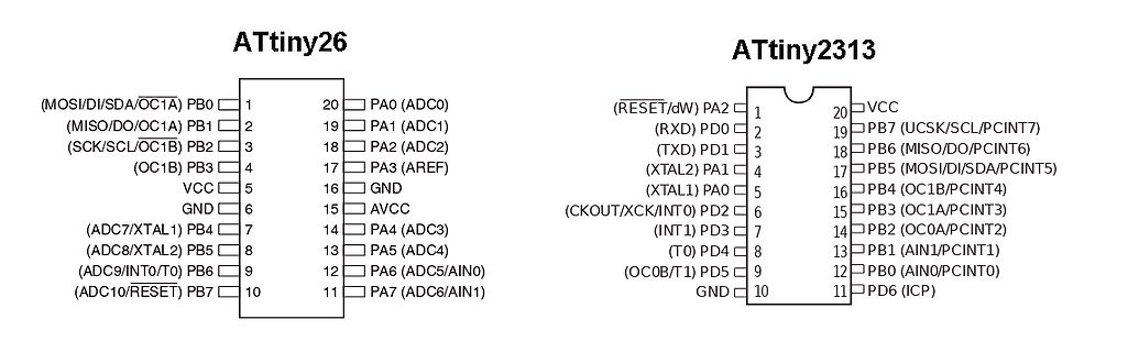
Pinbelegung ATtiny26 und ATtiny2313
(ADC8/XTAL2) PB5 8 13 PA5 (ADC4) (ADC9/INT0/T0) PB6 9 12 PA6 (ADC5/AIN0) (ADC10/RESET) PB7 10 11 PA7 (ADC6/AIN1) ATtiny2313 (RESET/dW) PA2 1 20 VCC (RXD) PD0 2 19 PB7 (UCSK/SCL/PCINT7) (TXD) PD1 3 18 PB6 (MISO/DO/PCINT6) (XTAL2) PA1 4 17 PB5 (MOSI/DI/SDA/PCINT5) (XTAL1) PA0 5 16 PB4 (OC1B/PCINT4
in „Suche Attiny26L-8SU (NOS)“ · Markt · · Screenshots
-
Datei
tn2313def__2_.inc
Y ;* ;* Number :AVR000 ;* File Name :"tn2313def.inc" ;* Title :Register/Bit Definitions for the ATtiny2313 ;* Date :03.06.17 ;* Version :1.00 ;* Support E-mail :avr@atmel.com ;* Target MCU :ATtiny2313 ;* ;* DESCRIPTION ;* When including this file in the assembly program file, all I/O register ;* names
in „Welche .def ist die richtige?“ · Mikrocontroller und Digitale Elektronik ·
-
Datei
dude5.4arduino_avr910.txt
flash:w:blink.hex:a -vvv -C ./avrdude.conf avrdude: Version 5.4-arduino, compiled on Oct 9 2007 at 11:20:31 Copyright (c) 2000-2005 Brian Dean, http://www.bdmicro.com/ System wide configuration file is "./avrdude.conf" User configuration file is "/Users/vinz/.avrduderc" User configuration file does not
in „avrdude - Probleme unter Mac OS X 10.7 (Lion)“ · Mikrocontroller und Digitale Elektronik ·