S S S M A A C A D T I Z 8 1 Q W R 8 1 1 C M C C P B W U U I S I S Q Q L E D E S S p (3) ü ü ü ü ATtiny4/5/9/10 6 0.5–1 0.032 1.8–5.5 12 10³ 4 2 1 4 ATtiny102/104 8/14 1 0.032 1.8–5.5 12 10 5/8 ü ü 2 2 ü ü 1 4 ATtiny13A 8–20 1 0.064 1.8–5.5 20 10 4 ü 2 ü ü ü ü 3 ü ATtiny20/40 12–20 2/4 0.128/0.256 1.8
einen Regelkreis in Planung (Spannungs- und Stromregelung), wobei ich einen AVR (im speziellen: ATTiny841) verwende. Dabei nutze ich die beiden internen Analogkomparatoren, welche laufend die gewünschte Ausgangsspannung (-strom) mit der realen Ausgangsspannung (-strom), welche bei einem Überschreiten
Der Weitere Programmablauf ist für mein eigentliches Problem nicht relevant. Da der Tiny841 (bzw. 441) die Komparatoreingänge mit den ADC-Eingängen doppelt belegt hat habe ich mir gedacht, dass ich ganz einfach den jeweiligen Analogpin auch gleich mit dem ADC verbinden kann und die Spannung/den Strom
aber weniger. Christoph db1uq K. schrieb im Beitrag #5999240: > Der billigste M4F von ST, STM32G441KBT6 bei Reichelt kostet > 4,30€ im LQFP32. Reichelt ist für sowas auch keine Referenz ;-)
notwendige hat (AES, CRC, EEPROM Raid1, time-sync, definierter Protokollstack) kommt noch mit einem attiny84A aus.
ich habe mich, nachdem ich immer nur mit Arduino und fertigen Funktionen gearbeitet habe, an einen Attiny45 rangemacht. Programmieren mit ISP und Atmel Studio 6 funktioniert gut, auch wenn die Handhabung etwas umständlich ist(Kompilieren, Fenster für den Programmer öffnen, Tab auswählen, Hochladen).
zugegeben muß, daß Atmel hier nicht gerade ein glückliches Händchen beim Mapping hatte. Naja, bei 441/841 haben sie ja gezeigt, wie sie das zukünftig bei den LPC-Teilen handhaben wollen. Mal sehen, ob es nach der Übernahme dazu überhaupt noch kommen wird...
Für ne Zahl mit 375 Dezimaltellen braucht man 156 Byte. Das ganze Programm paßt also dicke in nen ATtiny45 rein. Peter
127 18.015 ms 128 17.641 ms 129 17.777 ms 130 17.923 ms 131 18.188 ms 132 22.747 ms 133 18.441 ms 134 18.618 ms 135 18.778 ms 136 19.145 ms 137 19.179 ms 138 19.314 ms 139 20.207 ms 140 20.051 ms 141 19.850 ms 142 20.065 ms 143 20.303 ms 144 21.228 ms 145 20.541 ms 146 20.687 ms
Falk B. schrieb im Beitrag #6884634: > Man kann das auch in einem extra AVR, z.B. > ATtiny2313 machen, der dann die 8 Bits parallel ausgibt und per > Handshake an den "echten" Empfänger weitergibt. > So eine Art WS2812 UART. So in der Art dachte ich mir das auch. Man könnte die Daten
massiv variiert. Von Bitbanging über Timer, USART(SPI), USART(native) bis hin zum USI und den SPIs der 441/841 habe ich alles schonmal gebraucht und umgesetzt.
sich gerne bei mir melden. Zu den Eckdaten: - Grösse 50x50mm - FTDI FT232RL USB Chip - ATtiny 841/441 - Versorgung über CR2032 oder USB (3.3V) - bis zu 4 EEPROM Chips (24AA1026) mit je 128k x 8bit - micro SD-Karte vorgesehen Ich habe bisher nur die 2 EEPROM Chips wie auf den Bildern in
Hallo: Ich mnöchte gerne den integrierten Temperatursensor des ATTINY25 (http://www.atmel.com/dyn/resources/prod_documents/...) verwenden und stoße im Datenblatt auf Seite folgende Kalibrierungsformel: Zitat aus dem Datenblatt: " Software calibration can be done
Hi, schau mal bei Atmel die AppNote AVR441 an, da verwenden die einen Tiny25 dazu. PS: darin ist eine funktion "calibrate" enthalten.
auswertet. Das ist zumeist auch oberhalb der Grenzfrequenz der Geber. Neuerdings werde ich den ATtiny441 verwenden - noch kleiner und ebenfalls mit 100-fach Auswertung für sin/cos-Signale. Kosten Pro Kanal < 1€ avec plaisir.
stimmt erstens sowieso nicht (Gegenbeispiele, die ich auf Anhieb aus dem Kopf weiss: ATMega1284P, ATTiny441, ATTiny841, die haben allesamt zwei 16Bit-Timer) und zweitens ist es praktisch immer möglich, einen 8Bit-Timer durch Software auf 16 oder mehr Bit zu erweitern. Man muß halt einfach nur programmieren
that use slightly different algorithms are not supported. This applies to the following devices: ATtiny12, ATtiny15, ATtiny26, ATtiny2313, AT90S1200, AT90S2313, AT90S2323/2343, AT90S4433, AT90S8515 and AT90S8535. The bootloader module of AVROSP supports all devices with bootloader capabilities. Note: ATtiny11 and ATtiny28 do not support ISP or bootloader programming, and are not supported by AVROSP. The user could customize the code to support other programmers, e.g. a serial high-voltage programmer.
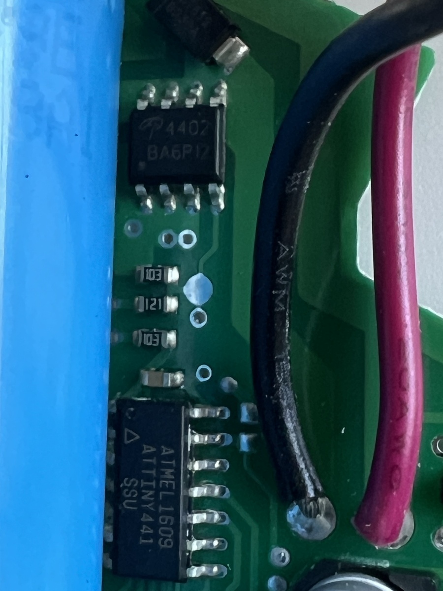
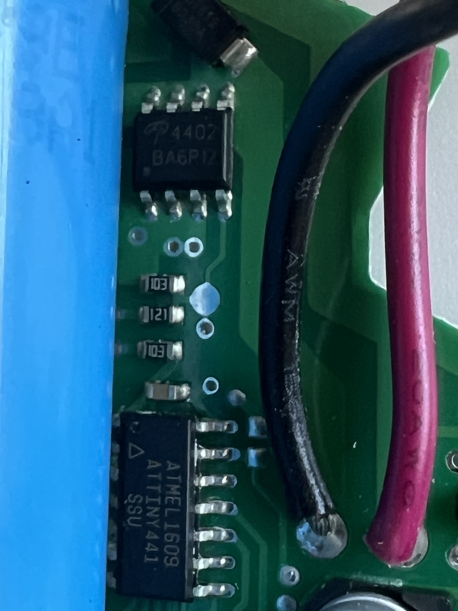
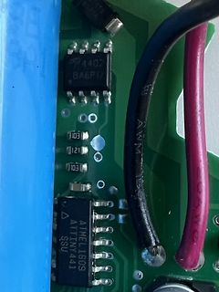
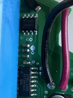
diesem Fehler. Checkt da die Schaltung was nicht richtig?! Bestückt ist sie mit 3 ICs: ATTMEL1609 ATtiny441, NB6N11S und TL431 u. einigen Transistoren. Ich weiß, dass das in dieser Preisklasse Liebhaberbemühung ist ... aber in Zeiten wie diesen möchte ich reparieren was geht. ;-) Danke für Ihr Verständnis
Hallo Beim Attiny441 gibt es ja die Möglichkeit, für SPI die Pins PA2, PA1, PA0 und PA3 zu verwenden statt PA7, PA6, PA5 und PA4 (default). Da ich an den default-Pins die ISP-Schnittstelle benötige, würde ich
A P P L I C A T I O N N O T E F O R T H E A V R F A M I L Y ;* ;* Number : AVR000 ;* File Name : tn441def.inc ;* Title : Register/Bit Definitions for the ATtiny441 ;* Created : 2017-10-02 18:57 ;* Version : 1.00 ;* Support e-mail : avr@atmel.com ;* Target MCU : ATtiny441 ;* ;* DESCRIPTION ;* When including
Ok muss ich mal durch probieren. Mir wäre der Attiny102 noch aufgefallen mit Uart und 1kb
Die ATtiny24/44/84 haben z.b. eine andere Belegung, die neue Reihe ATtiny441/ATtiny841 ebenfalls. Die ATtiny4/5/9/10 unter anderem, haben eine TPI Schnittstelle. PDI beherrscht mein Programmer auch, wird
includes two separate battery chargers. One using AT90S4433 AVR microcontroller and one using the ATtiny15 AVR microcontroller. The AT90S4433 design demonstrates how efficient a battery charger can be implemented with C-code. The ATtiny15 design shows the highest integrated and lowest cost battery charger
Ich weiß jetzt nicht genau auf welches Datenblatt Du Dich beziehst -- ich hatte es mir mal bei dem ATtiny26 genauer angesehen und habe gerade das Datenblatt des AT90USB vor mir. Ich denke das ist im Prinzip alles sehr ähnlich, bloß das ältere AVRs Gain 200 und differentielle Messung nicht können. Bei
dementsprechenden Entwurf gemacht. Die Anforderungen an die Trimpotis sind aber reichlich hoch. 6,372K und 441,5k einzustellen wird mit einem Poti kaum klappen... Damit ist die Theorie: 50 °C = 5,0V = 1000LSB 1000LSB/2 = 500LSB = 50,0°C
jemals) benötigen (werden). Um SX-Protokolle zu decodieren, reicht ein Tiny-Controller (bspw. Attiny441) locker aus. Wenn man ein Oszi oder einen LA hat und die Gleissignale schrittweise untersuchen kann, und wenn man dann auch noch Programmiererfahrung hat, dann sollte man das hinbekommen! Was an
the Peripheral Timer/Counter1. The nominal frequency of this peripheral clock, PCK, is 25.6 MHz. 4 ATtiny15L 1187DS–12/01 ATtiny15L ATtiny15L Register Summary Address Name Bit 7 Bit 6 Bit 5 Bit 4 Bit 3 Bit 2 Bit 1 Bit 0 Page $3F SREG I T H S V N Z C page 11 $3E Reserved $3C Reserved $3B GIMSK - INT0 PCIE
/* * VU Meter für ATTiny 25 (45/85) für 10 oder 12 LEDs (z.B. 9 grün, 2 gelb, 1 rot) * 15.3.17 * Anregung von https://www.mikrocontroller.net/topic/419372 - dort ist die HW mit einem Tiny13 beschrieben * * Taktfrequenz 8MHz
confusion. Deckblatt zeigt: 8-bit AVR Microcontrollers ATmega328/P DATASHEET COMPLETE und hat 441 Seiten Das von heute lautet ATmega328P 8-bit AVR Microcontroller with 32K Bytes In-System Programmable Flash DATASHEET hat 293 Seiten Danke & Gruesse
(Am STK500 samt Leitungen und Stecker liegt es nicht - Gegenprobe an anderen Prozessortypen (zB. ATtiny168) funktioniert) Bootloader funktioniert (immer noch) ...! Jetzt gehen mir so langsam die Ideen aus ...! Würde gern SPI wieder "gängig" kriegen - HVP (PP) ist einfach zu aufwendig. Jemand
/* * VU Meter für ATTiny25 (45/85) für 12 LEDs (z.B. 9 grün, 2 gelb, 1 rot) * 15.3.17, HildeK * Anregung von https://www.mikrocontroller.net/topic/419372 - dort ist die HW mit einem Tiny13 beschrieben * * Taktfrequenz 8MHz
Device Support The system software currently supports the following devices in all speed grades: n ATtiny11 n AT90S4433 n ATtiny12 n AT90S4434 n ATtiny15 n AT90S8515 n ATtiny22 n AT90S8535 n ATtiny28 n ATmega8 n AT90S1200 n ATmega16 n AT90S2313 n ATmega161 n AT90S2323 n ATmega163 n AT90S2333 n ATmega323
Device Support The system software currently supports the following devices in all speed grades: n ATtiny11 n AT90S4433 n ATtiny12 n AT90S4434 n ATtiny15 n AT90S8515 n ATtiny22 n AT90S8535 n ATtiny28 n ATmega8 n AT90S1200 n ATmega16 n AT90S2313 n ATmega161 n AT90S2323 n ATmega163 n AT90S2333 n ATmega323
2-2 for an example. A non-inclusive list of Atmel AVR devices with this feature includes: Atmel ATtiny10, ATtiny13, ATtiny20, ATtiny26, ATtiny28, ATtiny2313, ATmega48/88/168, ATmega8, ATmega16, ATmega32, ATmega8515/8535, ATmega162, ATmega164/324/644/ 1284, and ATmega165/325/3250/645/6450. 2 AVR205 8365A-AVR-01/11 AVR205 Figure 2-2. Atmel ATtiny13A pinout. 3 Measurement principle In this application note, the “gate-open” interval was chosen to be 0.1s, or 100ms, and so the signal to be measured will clock a counter for this time interval,
digitale Lösung b) umgeht diese Probleme. Messen und die Signale digitalisieren kann bereits ein ATtiny 13 recht gut. (http://www.elektronik-labor.de/AVR/T13contest/Seriell.html)
Chip der, das direkt kann (Analog in => RS-323)? Kleiner Mikrocontroller mit internem ADC zB. Tiny441 und ein RS485 Treiber zB. ein Texas THVD2410DR. mfg
Klar, die Zeiten, da das komplette Manual eines AT90S2343 (mehr oder minder ein Vorläufer des ATtiny15, der wiederum Vorläufer des ATtiny25/45/85 ist) auf nur 59 Seiten passte, sind vorbei. Heutige Controller fangen irgendwo bei 500 Seiten an, und selbst bei einem moderaten SAMD51 bist du schon bei
Applicability Application This application note applies to all AVRs with External RC Oscillator except ATtiny11, Note ATtiny12, ATtiny28, ATmega163, and ATmega323. For these devices, please refer to the device datasheets. Introduction This application note describes how to use the external RC oscillator for
that the firmware in the pro- grammer is outdated. The following devices are currently supported: ATtiny12 ATtiny15 ATtiny22 AT90S1200 AT90S2313 AT90S/LS2323 AT90S/LS2343 AT90S/LS2333 AT90S4414 AT90S/LS4433 AT90S/LS4434 AT90S8515 AT90S/LS8535 ATmega161(L) ATmega16(L) ATmega163(L) ATmega32(L) ATmega323
DWORD_WRITE Write double word Flash words (3) 0x1D CODE_WRITE Write flash words Notes: 1. Atmel ATtiny4/5/9/10 2. Atmel ATtiny20 3. Atmel ATtiny40 3.2.5.2 Addressing the flash The data space uses byte accessing, but because the flash sections are accessed as words and organized in pages, the byte address
Arne Groh '2011-06-20 ' 'Fusebits '1111 1111 '1111 1111 '1101 1111 '1110 0100 $regfile = "attiny2313.dat" $crystal = 8e6 Dim I As Byte Dim J As Integer Dim Ocr_0a As Word Dim Ocr0ah As Byte Dim Ocr0al As Byte Dim Ocr1a As Word Dim Ocr1b As Word Dim Flags As Byte Lastrun Alias Flags
are used for programming the Flash, EEPROM, Lock-bits and most Fuse-bits in all AVRs (except the ATtiny11 and ATtiny28). This feature makes it possible to program the AVR on the last stage of production of a target application board, reprogram if SW bugs are identified late in the process, or even update
Dallas 1wire-Controller ist auf dem CP) - IRDA - eigenes Material auf Fädelfläche - LCD - ich hatte 441xx und SED1520 dran - I2C Expander PCF8574 (Sockel) - I2C EEPROM 24xx (Sockel) -
Audioverstärker 20W - Lüfteranschluss/Heizungsanschluss - Peltier-Brücke DC 24V/6A - Watchdog ATTiny - Schaltregler 24V->5V - Größe 180x176mm Vom Board sind noch ein paar leere Platinen da, dazu noch ein paar Trinamic Module. Grüße, Marcus
für 3*10-bit PWM? Zwei 16Bit-Timer (und damit 4 16Bit-PWM-Kanäle) haben z.B.: Mega1284P Tiny441 Tiny841
entwickelt, und schon mit der ersten Version dieser lib lässt sich dein Beleuchtungsprojekt mit einem Attiny13 ! realisieren. Die Ws2812 hat zwar 'nur' 8bit pro Farbe, aber ich versteh' das ganze Gedöns mit 10bit und mehr nicht. Wenn du dein Teil mit einer Überblendungszeit von ca. 5 sec anstrahlst, hast
8MHz is offered in version 4.0. For later 4.x versions, two frequencies are offered: 4 and 8MHz for ATtiny2313, and 4.8 and 9.6MHz for the ATtiny13. The OSCCAL register is changed so that only 7 bits are used to tune the frequency for the selected oscillator. The MSB is not used. Auto loading of the default
must stay between GND and AV . CC Note that some devices cannot measure negative differences, e.g. ATtiny26. The need for calibration The total error of the actual ADC comes from more than just quantization error. This document describes offset and gain errors and how to compensate for them. It also describes
maximum value (512 using 10-bit ADC). Note that some devices cannot measure negative differences, e.g. ATtiny26. 2.3 The need for calibration The total error of the actual ADC comes from more than just quantization error. This document describes offset and gain errors and how to compensate for them. It also

 Bild
 Bild
 Bild