-
Datei
0001-Visual-Studio-2015-Files.patch
Include="src\atmega668base.h" /> + <ClInclude Include="src\atmega8.h" /> + <ClInclude Include="src\attiny2313.h" /> + <ClInclude Include="src\attiny25_45_85.h" /> + <ClInclude Include="src\avrdevice.h" /> + <ClInclude Include="src\avrdevice_impl.h" /> + <ClInclude Include="src\avrerror.h" /> + <ClInclude
in „Simulavr unter Windows mit Visual Studio 2015 kompilieren“ · Mikrocontroller und Digitale Elektronik ·
-
Datei
tiny_oled_spi_3wire_b.ino
3wire.ino Demoprogramm zum Anbinden eines SSD1306 OLED-Displays mit nur 3 benoetigten I/O Leitungen des ATtiny-Controllers. Demoprogramm hier fuer ATtiny44/84. Programm sollte durch Abaenderung der Anschlusspins auch auf ATtiny45/85 lauffaehig sein, da die SPI-Schnittstelle nur mittels Bitbanging (und nicht
in „ATtiny85 benötige Taster und kein freier Port“ · Mikrocontroller und Digitale Elektronik ·
-
PDF
ATtiny212_40001911A.pdf
Technology Inc. ATtiny212/412 9.2. Overview.................................................................................................................................... 45 9.3. Functional Description..............
in „Neue 8-Bit Tinys vorgestellt: 417/814/816/817“ · Mikrocontroller und Digitale Elektronik ·
-
Datei
USI_TWI_Master.asm
define PORT_USI_SCL PORTE4 #define PIN_USI_SDA PINE5 #define PIN_USI_SCL PINE4 #elif defined(__AVR_ATtiny25__) | defined(__AVR_ATtiny45__) | defined(__AVR_ATtiny85__) | \ defined(__AVR_AT90Tiny26__) | defined(__AVR_ATtiny26__) #define DDR_USI DDRB #define PORT_USI PORTB #define PIN_USI PINB #define PORT_USI_SDA
in „C->Asm (TWI) Fehlersuche“ · Mikrocontroller und Digitale Elektronik ·
-
Datei
AVRrescue.c
0x06, 0xC0, 00, 00}, // ATtiny15 {0x1E, 0x90, 0x07, 0x6A, 0xFF, 00}, // ATtiny13 {0x1E, 0x90, 0x08, 00, 00, 00}, // ATtiny9 {0x1E, 0x90, 0x0A, 00, 00, 00}, // ATtiny4 {0x1E, 0x91, 0x01, 0xDF, 00, 00}, // AT90S2313 {0x1E, 0x91, 0x02
in „AVR-Rescue: standalone Parallel HV-Programmer“ · Projekte & Code ·
-
PDF
STK500-HW-Beschreibung.pdf
Die Systemsoftware unterstützt zur Zeit folgende AVR’s in allen Ge- schwindigkeitsstufen (MHz): • ATtiny11 • AT90S4433 • ATtiny12 • AT90S4434 • ATtiny15 • AT90S8515 • ATtiny22 • AT90S8535 • ATtiny28 • ATmega8 • AT90S1200 • ATmega16 • AT90S2313 • ATmega161 • AT90S2323 • ATmega163 • AT90S2333 • ATmega323
in „deutsche version vom stk500 handbuch“ · Mikrocontroller und Digitale Elektronik ·
-
PDF
STK500-HW-Beschreibung.pdf
Die Systemsoftware unterstützt zur Zeit folgende AVR’s in allen Ge- schwindigkeitsstufen (MHz): • ATtiny11 • AT90S4433 • ATtiny12 • AT90S4434 • ATtiny15 • AT90S8515 • ATtiny22 • AT90S8535 • ATtiny28 • ATmega8 • AT90S1200 • ATmega16 • AT90S2313 • ATmega161 • AT90S2323 • ATmega163 • AT90S2333 • ATmega323
in „Handbuch/Anleitung zu AVR STK 500“ · Mikrocontroller und Digitale Elektronik ·
-
PDF
STK500-HW-Beschreibung.pdf
Die Systemsoftware unterstützt zur Zeit folgende AVR’s in allen Ge- schwindigkeitsstufen (MHz): • ATtiny11 • AT90S4433 • ATtiny12 • AT90S4434 • ATtiny15 • AT90S8515 • ATtiny22 • AT90S8535 • ATtiny28 • ATmega8 • AT90S1200 • ATmega16 • AT90S2313 • ATmega161 • AT90S2323 • ATmega163 • AT90S2333 • ATmega323
in „Einstieg mit dem AVR STK 500“ · Mikrocontroller und Digitale Elektronik ·
-
PDF
STK500-HW-Beschreibung.pdf
Die Systemsoftware unterstützt zur Zeit folgende AVR’s in allen Ge- schwindigkeitsstufen (MHz): • ATtiny11 • AT90S4433 • ATtiny12 • AT90S4434 • ATtiny15 • AT90S8515 • ATtiny22 • AT90S8535 • ATtiny28 • ATmega8 • AT90S1200 • ATmega16 • AT90S2313 • ATmega161 • AT90S2323 • ATmega163 • AT90S2333 • ATmega323
in „Einsteigerfragen zu STK-500“ · Mikrocontroller und Digitale Elektronik ·
-
PDF
STK500-HW-Beschreibung.pdf
Die Systemsoftware unterstützt zur Zeit folgende AVR’s in allen Ge- schwindigkeitsstufen (MHz): • ATtiny11 • AT90S4433 • ATtiny12 • AT90S4434 • ATtiny15 • AT90S8515 • ATtiny22 • AT90S8535 • ATtiny28 • ATmega8 • AT90S1200 • ATmega16 • AT90S2313 • ATmega161 • AT90S2323 • ATmega163 • AT90S2333 • ATmega323
in „++++Programmübertragung auf STK500++++“ · Mikrocontroller und Digitale Elektronik ·
-
PDF
STK500-HW-Beschreibung.pdf
Die Systemsoftware unterstützt zur Zeit folgende AVR’s in allen Ge- schwindigkeitsstufen (MHz): • ATtiny11 • AT90S4433 • ATtiny12 • AT90S4434 • ATtiny15 • AT90S8515 • ATtiny22 • AT90S8535 • ATtiny28 • ATmega8 • AT90S1200 • ATmega16 • AT90S2313 • ATmega161 • AT90S2323 • ATmega163 • AT90S2333 • ATmega323
in „STK500 - welcher Prozessor in welchem Sockel?“ · Mikrocontroller und Digitale Elektronik ·
-
PDF
STK500-HW-Beschreibung.pdf
Die Systemsoftware unterstützt zur Zeit folgende AVR’s in allen Ge- schwindigkeitsstufen (MHz): • ATtiny11 • AT90S4433 • ATtiny12 • AT90S4434 • ATtiny15 • AT90S8515 • ATtiny22 • AT90S8535 • ATtiny28 • ATmega8 • AT90S1200 • ATmega16 • AT90S2313 • ATmega161 • AT90S2323 • ATmega163 • AT90S2333 • ATmega323
in „Evaluation Boards“ · Mikrocontroller und Digitale Elektronik ·
-
PDF
STK500-HW-Beschreibung.pdf
Die Systemsoftware unterstützt zur Zeit folgende AVR’s in allen Ge- schwindigkeitsstufen (MHz): • ATtiny11 • AT90S4433 • ATtiny12 • AT90S4434 • ATtiny15 • AT90S8515 • ATtiny22 • AT90S8535 • ATtiny28 • ATmega8 • AT90S1200 • ATmega16 • AT90S2313 • ATmega161 • AT90S2323 • ATmega163 • AT90S2333 • ATmega323
in „STK500 mit AVRDRAGON via JTAG verbinden“ · Mikrocontroller und Digitale Elektronik ·
-
PDF
STK500_HW_BESCHREIBUNG_2.PDF
Die Systemsoftware unterstützt zur Zeit folgende AVR’s in allen Ge- schwindigkeitsstufen (MHz): • ATtiny11 • AT90S4433 • ATtiny12 • AT90S4434 • ATtiny15 • AT90S8515 • ATtiny22 • AT90S8535 • ATtiny28 • ATmega8 • AT90S1200 • ATmega16 • AT90S2313 • ATmega161 • AT90S2323 • ATmega163 • AT90S2333 • ATmega323
in „Suche deutsche Übersetzung für STK500“ · Mikrocontroller und Digitale Elektronik ·
-
PDF
STK500-HW-Beschreibung.pdf
Die Systemsoftware unterstützt zur Zeit folgende AVR’s in allen Ge- schwindigkeitsstufen (MHz): • ATtiny11 • AT90S4433 • ATtiny12 • AT90S4434 • ATtiny15 • AT90S8515 • ATtiny22 • AT90S8535 • ATtiny28 • ATmega8 • AT90S1200 • ATmega16 • AT90S2313 • ATmega161 • AT90S2323 • ATmega163 • AT90S2333 • ATmega323
in „STK500 als ISP“ · Mikrocontroller und Digitale Elektronik ·
-
PDF
stk500user_guide_de.pdf
Die Systemsoftware unterstützt zur Zeit folgende AVR’s in allen Ge- schwindigkeitsstufen (MHz): • ATtiny11 • AT90S4433 • ATtiny12 • AT90S4434 • ATtiny15 • AT90S8515 • ATtiny22 • AT90S8535 • ATtiny28 • ATmega8 • AT90S1200 • ATmega16 • AT90S2313 • ATmega161 • AT90S2323 • ATmega163 • AT90S2333 • ATmega323
in „ATmega32 ISP“ · Mikrocontroller und Digitale Elektronik ·
-
Datei
Synth.asm
, 120, 120,120, 120, 120, 120,120, 120, 120, 120 .db 0,1,3,5, .db 8,11,15,19, .db 23,28,34,40, .db 45,52,58,64 .db 70,76,83,88, .db 94,100,105,109, .db 113,117,120,123, .db 125,127,128,128, .db 128,127,125,123, .db 120,117,113,109, .db 105,100,94,88, .db 83,76,70,64, .db 58,52,45,40, .db 34,28,23,19, .db 15,11,8,5, .db 3,1,0,0, .db 0,1,3,5, .db 8,11,15,19, .db 23,28,34,40, .db 45,52,58,64, .db 70,76,83,88, .db 94,100,105,109, .db 113,117,120,123, .db 125,127,128,128, .db 128,127,125,123, .db 120,117,113,109, .db 105,100,94,88, .db 83,76,70,64, .db 58,52,45,40, .db 34,28,23,19
in „Attiny2313 Timer16 Bit, Normal Mode, unsauber“ · Mikrocontroller und Digitale Elektronik ·
-
Datei
fuse.c
programmable attinys * . reset hi-low fuses to factory default on target devices * . layout to drop-on attiny13, attiny25/45/85 8 pin devices targets * . attiny24/44/84 targets needs additional breadboard and jumper wires * . standalone operations, fuses show on 7 segment display * * . project fuse setting
in „Attiny85 neu verfust?“ · Mikrocontroller und Digitale Elektronik ·
-
 Bild
Bild
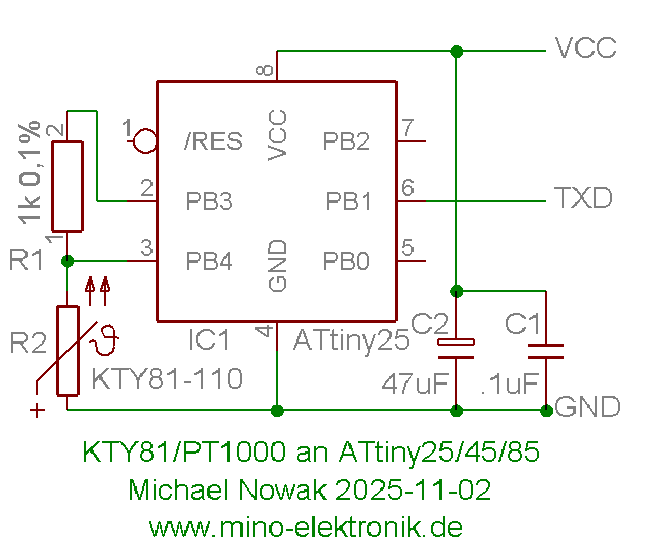
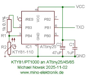
Schaltplan ATtiny25 mit PT1000 Widerstand
VCC 8 /RES 1 1k 0,1% 2 PB3 3 PB4 4 GND IC1 ATtiny25 5 PB0 6 PB1 TXD 7 PB2 VCC 8 C2 47uF C1 .1uF GND R1 R2 KTY81-110 + KTY81/PT1000 an ATtiny25/45/85 Michael Nowak 2025-11-02 www.mino-elektronik.de
in „KTY81/PT1000 an Attiny mit ser. Ausgabe“ · Projekte & Code · · Schaltpläne
-
 Bild
Bild
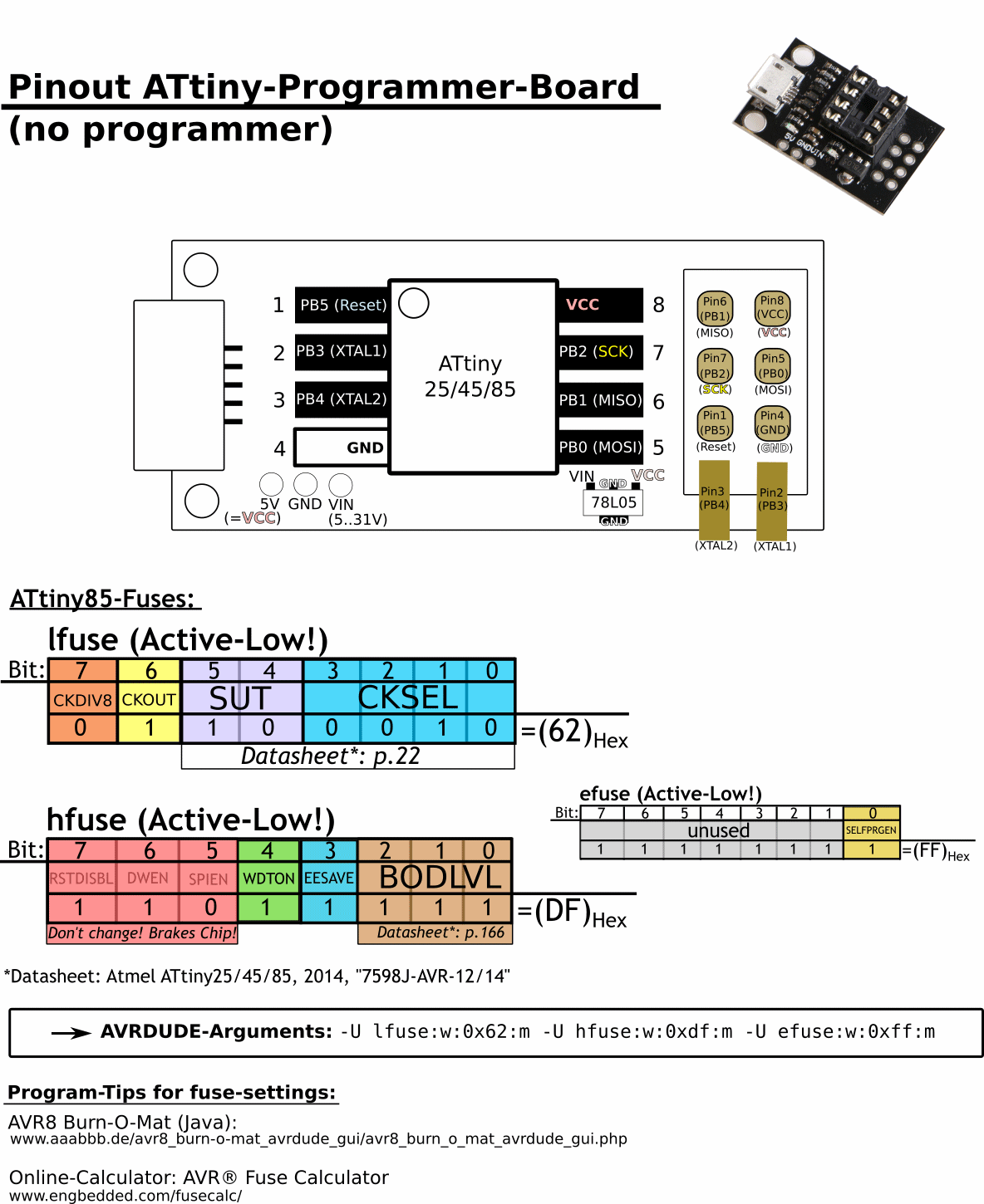
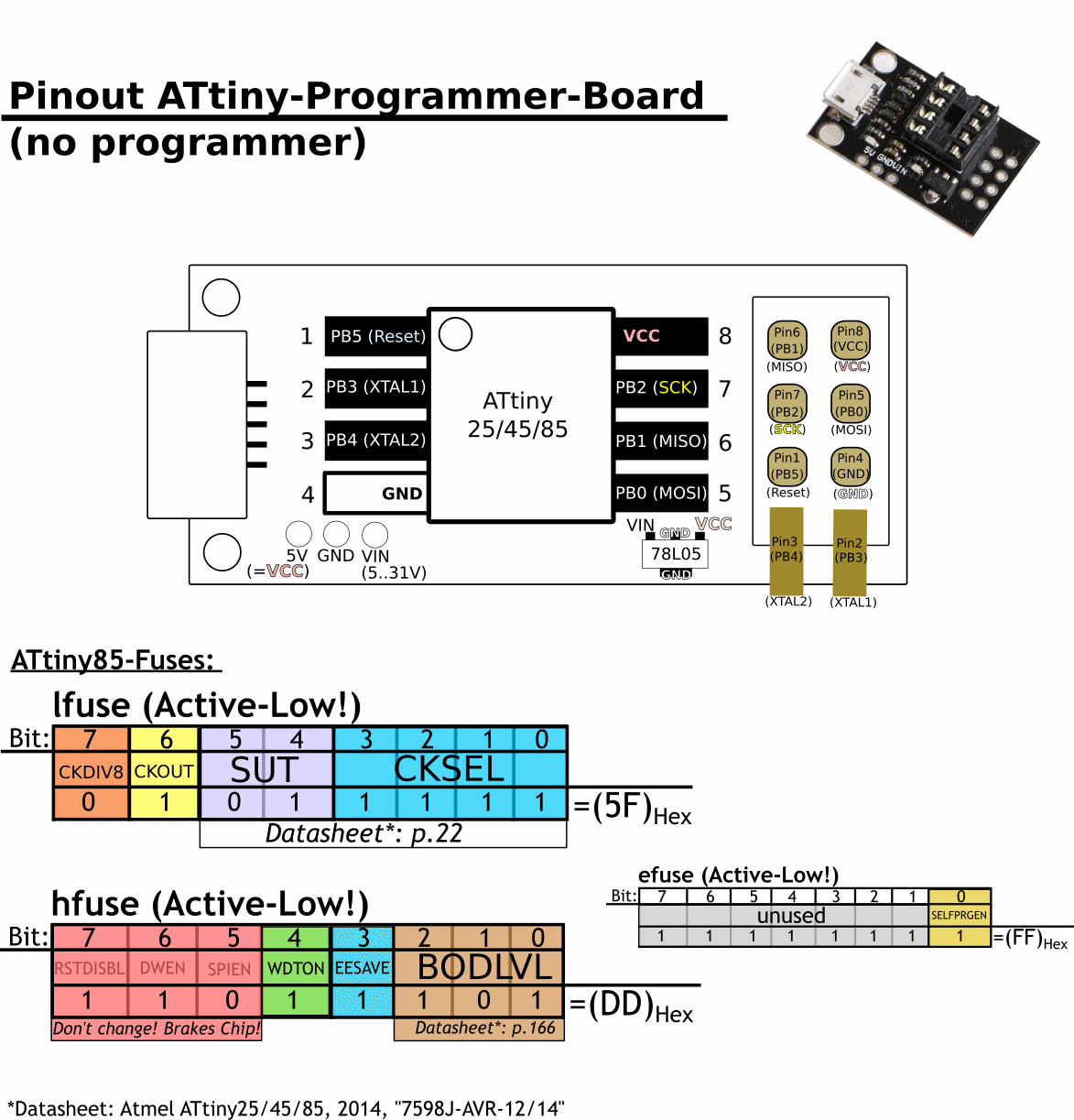
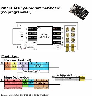
Pinout und Fuse-Einstellungen ATtiny-Programmer-Board
Pinout ATtiny-Programmer-Board (no programmer) PB5 (Reset) VCC PB3 (XTAL1) PB2 (SCK) PB3 (XTAL2) GND PB1 (MISO) PB0 (MOSI) VIN 78L05 ATtiny25/45/85 Fuse lfuse (Active-Low!) CKDIV8 CKOUT SUT CKSEL (62)Hex hfuse (
in „Pinout ATtiny-"Programmer"-Board“ · Mikrocontroller und Digitale Elektronik · · Screenshots
-
 Bild
Bild
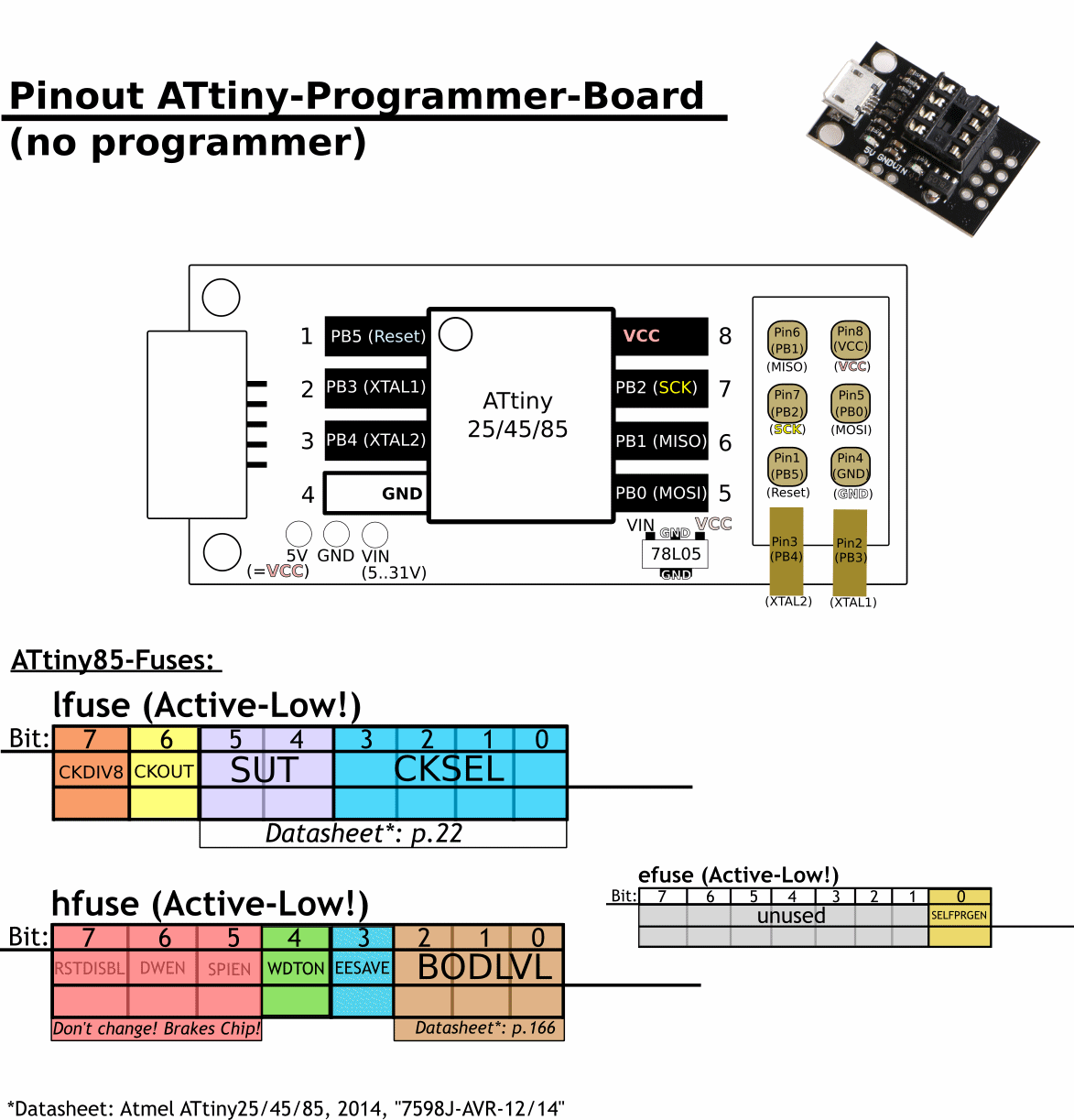
Pinout ATtiny-Programmer-Board und Fuse-Bit-Übersicht
Pinout ATtiny-Programmer-Board (no programmer) 1 PB5 (Reset) 2 PB3 (XTAL1) 3 PB4 (XTAL2) 4 GND 8 VCC Pin6 (PB1) (MISO) Pin8 (VCC) 7 PB2 (SCK) Pin7 (PB2) (SCK) Pin5 (PB0) (MOSI) PB1 (MISO) 6 PB0 (MOSI) 5 VIN GND VIN (5..31V) VCC 78L05 ATtiny25/45/85: efuse (Active-Low!) hfuse (Active-Low!) BODLVL SELFPRGEN RSTDISBL DWEN SPIEN WDTN EESAVE
in „Pinout ATtiny-"Programmer"-Board“ · Mikrocontroller und Digitale Elektronik · · Diagramme
-
 Bild
Bild
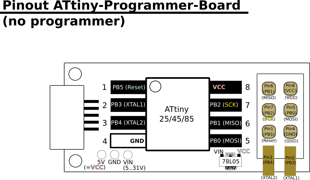
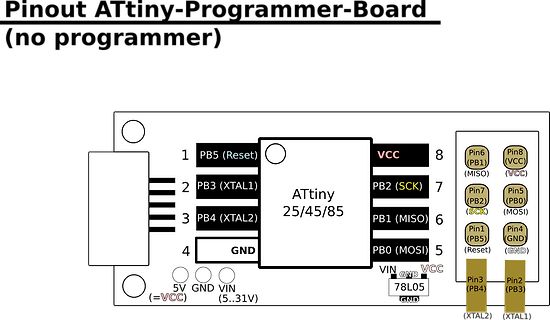
Pinout einer ATtiny-Programmierplatine
Pinout ATtiny-Programmer-Board (no programmer) 1 PB5 (Reset) 2 PB3 (XTAL1) 3 PB4 (XTAL2) 4 GND 5 PB0 (MOSI) 6 PB1 (MISO) 7 PB2 (SCK) 8 VCC Pin6 (PB1) (MISO) Pin8 (VCC) Pin7 (PB2) (SCK) Pin5 (PB0) (MOSI) Pin1 (PB5) (Reset) Pin4 (GND) (GND) Pin3 (PB4) (XTAL2) Pin2 (PB3) (XTAL1) ATtiny 25/45/85 VCC 5V GND VIN (5..31V) 78L05 GND VIN GND VCC
in „Pinout ATtiny-"Programmer"-Board“ · Mikrocontroller und Digitale Elektronik · · Diagramme
-
 Bild
Bild
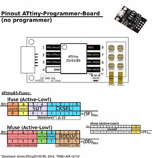
Pinout ATtiny-Programmer-Board und Fuse-Einstellungen
Pinout ATtiny-Programmer-Board (no programmer) 1 PB5 (Reset) 2 PB3 (XTAL1) 3 PB4 (XTAL2) 4 GND 8 VCC Pin6 (PB1) (MISO) Pin8 (VCC) 7 PB2 (SCK) Pin7 (PB2) (SCK) Pin5 (PB0) (MOSI) 6 PB1 (MISO) Pin4 (PB5) (Reset) Pin0 (GND) (BID) 5 PB0 (MOSI) VIN GND 5V (=VCC) VIN (5..31V) 78L05 PB3 (XTAL1) PB4 (XTAL2) ATtiny 25/45/85 ifuse (Active-Low!) hfuse (Active-Low!) Datasheet*: p.22 Datasheet*: p.166
in „Pinout ATtiny-"Programmer"-Board“ · Mikrocontroller und Digitale Elektronik · · Screenshots
-
Datei
Original.c.c
/*************************************************************************************** Titel: ATtiny TPS Author: Christian Hottum File: ATtiny461A_TPS.c Version: 0.1 Datum: 09.01.2015 Software: AVR-GCC 4.3.3 Target: ATtiny461A DESCRIPTION Firmware für einen Tasten Programierbare Steuerung auf Basis
in „Ttiny 461a isp schaltung“ · Mikrocontroller und Digitale Elektronik ·
-
Datei
attiny85.c
// Manipulation E-Bike-Tachosignal mit ATTINY25/45/85 // -------------------------------------------------- // NUR AUF DEM SCHREIBTISCH GETESTET!!! // ergokey240 // @ // gmail.com // // Idee und Schaltung: https://www.mikrocontroller.net/topic
in „Bosch E-Bike Antrieb Geschwindigkeitssensor“ · Fahrzeugelektronik ·
-
 Bild
Bild
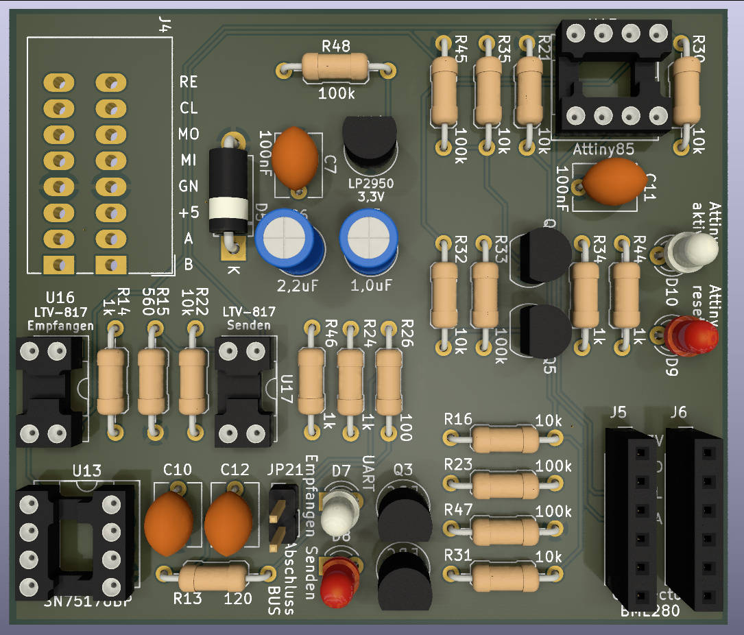
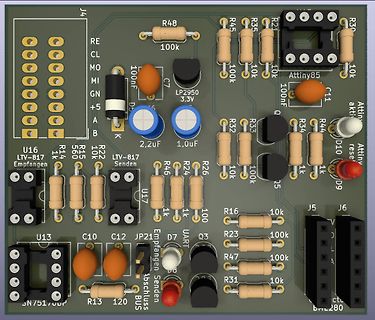
CAD-Ansicht eines Leiterplatten-Layouts
J4 R48 R45 R35 R21 R30 100k 10k 10k RE CL MO MI GN +5 A B K 100nF C7 LP2950 3,3V 100nF C11 Attiny85 Attiny akti D10 R34 R44 R33 R32 10k 10k 1k 1k 1k Q5 D9 R26 R24 R46 100 1k 1k LTV-817 Senden LTV-817 Empfangen
in „BME280 mit Attiny85 auslesen Daten per SN75176 an Pi senden“ · Mikrocontroller und Digitale Elektronik · · Layouts
-
Datei
Values.txt
BC8017 1 BC637 1 BC557C 1 bc550 1 BC547 Zündung 1 BC547 Mikrocontroller 1 BC307 1 BAT49 1 BAT46 1 BAT45 1 BAT42 1 BAS216 1 BACK_LIGHT 1 B82131 1 B80C1500 1 B40C1500 1 B2,54 1 AVR_XMEGA_A3_ 1 AVR-JTAG-10 1 AVR ISP 1 AVR 1 Aux_In 1 AUX 1 Ausgang 1 AtTINY45 1 ATTINY28 1 ATTINY26P 1 AT Tiny26 1 ATTINY24 1 ATTINY2313-20P 1 ATtiny2313 1 ATMEGA8-16P 1 ATMEGA640-16AU 1 ATMEGA48-20A 1 ATMEGA32U4-AU 1 ATMEGA2560-16AU 1 AT_MEGA16P 1 ATMEGA168-20A 1 ATMEGA164-20A 1 ATMEGA128_TQPF 1 ATiny2313 1 AT93C46 1 AT91SAM7X512
in „[KiCad] Bibliotheksaufbau - Konzeptideen gesucht“ · Platinen ·
-
Datei
Sender.c
include <string.h> #include <stdio.h> #include <stdlib.h> void timer1_init (void) { #if defined (__AVR_ATtiny45__) || defined (__AVR_ATtiny85__) OCR1C = (F_CPU / F_INTERRUPTS / 4) - 1; TCCR1 = (1 << CTC1) | (1 << CS11) | (1 << CS10); #else OCR1A = (F_CPU / F_INTERRUPTS) - 1; TCCR1B = (1 << WGM12) | (1 << CS10
in „IR-Emfänger TSOP 4838 an ATmega328P“ · Mikrocontroller und Digitale Elektronik ·
-
Datei
Sender.c
include <string.h> #include <stdio.h> #include <stdlib.h> void timer1_init (void) { #if defined (__AVR_ATtiny45__) || defined (__AVR_ATtiny85__) OCR1C = (F_CPU / F_INTERRUPTS / 4) - 1; TCCR1 = (1 << CTC1) | (1 << CS11) | (1 << CS10); #else OCR1A = (F_CPU / F_INTERRUPTS) - 1; TCCR1B = (1 << WGM12) | (1 << CS10
in „IR-Emfänger TSOP 4838 an ATmega328P“ · Mikrocontroller und Digitale Elektronik ·
-
Datei
Sender.c
include <string.h> #include <stdio.h> #include <stdlib.h> void timer1_init (void) { #if defined (__AVR_ATtiny45__) || defined (__AVR_ATtiny85__) OCR1C = (F_CPU / F_INTERRUPTS / 4) - 1; TCCR1 = (1 << CTC1) | (1 << CS11) | (1 << CS10); #else OCR1A = (F_CPU / F_INTERRUPTS) - 1; TCCR1B = (1 << WGM12) | (1 << CS10
in „IR-Emfänger TSOP 4838 an ATmega328P“ · Mikrocontroller und Digitale Elektronik ·
-
PDF
doc8373.pdf
DWORD_WRITE Write double word Flash words (3) 0x1D CODE_WRITE Write flash words Notes: 1. Atmel ATtiny4/5/9/10 2. Atmel ATtiny20 3. Atmel ATtiny40 3.2.5.2 Addressing the flash The data space uses byte accessing, but because the flash sections are accessed as words and organized in pages, the byte address
in „Neue 8-Bit Tinys vorgestellt: 417/814/816/817“ · Mikrocontroller und Digitale Elektronik ·
-
Datei
Empfaenger.c
RXEN0); UCSR0C = (1<<UCSZ00) | (1<<UCSZ01); } static void timer1_init (void) { #if defined (__AVR_ATtiny45__) || defined (__AVR_ATtiny85__) #if F_CPU >= 16000000L OCR1C = (F_CPU / F_INTERRUPTS / 8) - 1; TCCR1 = (1 << CTC1) | (1 << CS12); #else OCR1C = (F_CPU / F_INTERRUPTS / 4) - 1; TCCR1 = (1 << CTC1
in „IR-Emfänger TSOP 4838 an ATmega328P“ · Mikrocontroller und Digitale Elektronik ·
-
PDF
ATtiny261A_Complete.pdf
VCCRISING V ( 1.82 o s r 1.81 T 1.8 VCCFALLING 1.79 1.78 -40 -20 0 20 40 60 80 100 Temperature (C) 220 ATtiny261A/461A/861A 8197C–AVR–05/11 ATtiny261A/461A/861A Figure 20-45. Bandgap Voltage vs. Supply Voltage. BANDGAP VOLTAGE vs. V CC 1.11 1.1 85 °C V 25 °C ( g l V 1.09 p g n a B 1.08 -40 °C 1.07 1.5 2.5
in „USI Interface als SPI Schnittstelle beim ATtiny261A“ · Mikrocontroller und Digitale Elektronik ·
-
PDF
Minimalistischer_GPS_Logger.pdf
Quectel Auch dieser Baustein ist minimalistisch – allerdings nur von der Größe her – 16 mm x 16 mm x 6,45mm. Das Gehäuse mit integrierter Antenne hat 12-pin 2.54mm pitch SMT Anschlüsse, die entweder direkt ohne Draht auf typische durchkontaktierte Experimental-Leiterplatten mit gleichem Rastermaß gelötet
in „Minimalistischer GPS-Logger ohne µC und SD-Karte“ · Mikrocontroller und Digitale Elektronik ·
-
Datei
oled_2313demo.c
Minimalprogramm fuer Textausgabe auf einem OLED-Display mit SSD1306 oder SSD1315 Display, explizit fuer einen ATtiny2313 Mikrocontroller MCU : ATtiny2313 Takt : 8 MHz Fuses : Low: 0xe4 | High: 0xdf | Ext: 0xff IDE : keine 25.02.2026 R. seelig ------------------------------------------------------ */ /* ATTINY2313
in „I2C Display einfache Frage“ · Mikrocontroller und Digitale Elektronik ·
-
Datei
felermeldung.txt
Send: 0 [30] [20] avrdude: Send: 0 [30] [20] avrdude: Recv: . [14] avrdude: Recv: . [10] AVR Part : ATtiny85 Chip Erase delay : 400000 us PAGEL : P00 BS2 : P00 RESET disposition : possible i/o RETRY pulse : SCK serial program mode : yes parallel program mode : yes Timeout : 200 StabDelay : 100 CmdexeDelay
in „Fehler beim Flashen des ATtiny85 mit dem Arduino uno“ · Mikrocontroller und Digitale Elektronik ·
-
Datei
Attiny25.txt
/******************************************************* Projekt: Aetzwanne Version : ATTiny25 - 1 Erstellt: 20.09.2016 Letze Aenderung: 25.09.2016 Chip: Attiny25 mit internen 8.0 MHz *******************************************************/ /// Header-Dateien/// #include <io.h> #include <delay.h
in „AVR ADC auswerten klappt nicht“ · Mikrocontroller und Digitale Elektronik ·
-
PDF
mikrobeginner_gesamt.pdf
cWort4,cWort3,cWort2,cWort1 Seite 168 12.5.8 Analyse der gesendeten Signale Das hier ist, was der ATtiny45 von den Signalen so mitbekommen hat. Die beiden ersten Kopfsi- gnale sind mit 0x1901 und 0x0288 (51.208 und 5.184 µs) etwas zu lang. Dass die Anzahl der Kopfsignale bei der Senderoutine extrem groß
in „Attiny26 PortD“ · Mikrocontroller und Digitale Elektronik ·
-
Datei
attiny24_mit_5_led.c
#ifndef F_CPU #define F_CPU 8000000UL #endif #define MCU attiny24 /* Fuses für den Dude: LFUSE = 62 HFUSE = d7 // Abweichung ggü Default (df): EESAVE EFUSE = ff */ #include <stdint.h> #include <avr/io.h> #include <util/delay.h> uint8_t i; void led(uint8_t ledNumber
in „ATtiny24-Rätsel, PB0 wird nicht high“ · Mikrocontroller und Digitale Elektronik ·
-
PDF
tinyloaderB.pdf
Pedersen tinyloader@kasperkp.dk http://tinyloader.kasperkp.dk Overview Microcontrollers such as ATTiny13/24/45/85 look good on paper; Only eight pins, and tiny little SMT packages. Perfect for that clock divider or egg timer functionality. The only problem is: To reprogram them one needs to provide
in „Micronucleus - USB-Bootloader für ATtiny“ · Projekte & Code ·
-
Datei
dude5.4arduino_avr910.txt
0x52 = (unknown) Device code: 0x53 = (unknown) Device code: 0x54 = (unknown) Device code: 0x55 = ATtiny12 Device code: 0x56 = ATtiny15 Device code: 0x57 = (unknown) Device code: 0x58 = (unknown) Device code: 0x59 = (unknown) Device code: 0x5a = (unknown) Device code: 0x5b = (unknown) Device code: 0x5c = (unknown) Device code: 0x5d = (unknown) Device code: 0x5e = ATtiny2313 Device code: 0x5f = (unknown) Device code: 0x60 = ATMEGA161 Device code: 0x61 = (unknown) Device code: 0x62 = (unknown) Device code: 0x63 = ATMEGA162 Device code: 0x64 = ATMEGA163 Device code:
in „avrdude - Probleme unter Mac OS X 10.7 (Lion)“ · Mikrocontroller und Digitale Elektronik ·
-
Datei
dude5.6_avr910.txt
0x52 = (unknown) Device code: 0x53 = (unknown) Device code: 0x54 = (unknown) Device code: 0x55 = ATtiny12 Device code: 0x56 = ATtiny15 Device code: 0x57 = (unknown) Device code: 0x58 = (unknown) Device code: 0x59 = (unknown) Device code: 0x5a = (unknown) Device code: 0x5b = (unknown) Device code: 0x5c = (unknown) Device code: 0x5d = (unknown) Device code: 0x5e = ATtiny2313 Device code: 0x5f = (unknown) Device code: 0x60 = ATMEGA161 Device code: 0x61 = (unknown) Device code: 0x62 = (unknown) Device code: 0x63 = ATMEGA162 Device code: 0x64 = ATMEGA163 Device code:
in „avrdude - Probleme unter Mac OS X 10.7 (Lion)“ · Mikrocontroller und Digitale Elektronik ·
-
Datei
dude54arduino.txt
0x52 = (unknown) Device code: 0x53 = (unknown) Device code: 0x54 = (unknown) Device code: 0x55 = ATtiny12 Device code: 0x56 = ATtiny15 Device code: 0x57 = (unknown) Device code: 0x58 = (unknown) Device code: 0x59 = (unknown) Device code: 0x5a = (unknown) Device code: 0x5b = (unknown) Device code: 0x5c = (unknown) Device code: 0x5d = (unknown) Device code: 0x5e = ATtiny2313 Device code: 0x5f = (unknown) Device code: 0x60 = ATMEGA161 Device code: 0x61 = (unknown) Device code: 0x62 = (unknown) Device code: 0x63 = ATMEGA162 Device code: 0x64 = ATMEGA163 Device code:
in „avrdude - Probleme unter Mac OS X 10.7 (Lion)“ · Mikrocontroller und Digitale Elektronik ·
-
Datei
tiny12test.lst
/../Desktop/tiny12test.hex Eepromdatei: ../../../Desktop/tiny12test.eep Kompiliert: 19.03.2010, 19:45:15 Durchgang: 2 1: ; Target MCU: ATtiny12 2: .NOLIST 5: 6: ; REGISTER LIST 7: ; 8: ; r16 set I/O 9: ; r17 load Inputs and compare them 10: ; r18 (not used yet) 11: ; r19 set nop cycles 12: ; r20 set
in „[AVR|ASM] LED-Controller mit ATtiny12“ · Mikrocontroller und Digitale Elektronik ·
-
PDF
AVR4100.pdf
MegaAVR ATmega88P X32K_1v8_ULP MegaAVR ATmega88PA X32K_1v8_ULP MegaAVR ATmega8A X32K_2v7 TinyAVR ATtiny2313A X32K_1v8 TinyAVR ATtiny24 X32K_1v8 TinyAVR ATtiny24A X32K_1v8 TinyAVR ATtiny25 X32K_1v8 TinyAVR ATtiny261 X32K_1v8 TinyAVR ATtiny261A X32K_1v8 TinyAVR ATtiny4313 X32K_1v8 TinyAVR ATtiny44 X32K_1v8 TinyAVR ATtiny44A X32K_1v8 TinyAVR ATtiny45 X32K_1v8 TinyAVR ATtiny461 X32K_1v8 TinyAVR ATtiny461A X32K_1v8 TinyAVR ATtiny84 X32K_1v8 TinyAVR ATtiny861A X32K_1v8 XMEGA ATxmega128A1 X32K_XMEGA XMEGA ATxmega128A3 X32K_XMEGA
in „Passende Kondensatoren für Uhrenquarz gesucht“ · Mikrocontroller und Digitale Elektronik ·
-
PDF
Briefkasten.pdf
3,3 330n R1 8 GND D 10k C G U1 C D1 GND V 5 2 J1 / Vin AREF/PB0 1k LED D PB1 6 R6 N 1 NODEMCU B C1 ATtiny45V-10PU PB2 7 G / GND B 100n 2 2 XTAL1/PB3 XTAL2/PB4 3 1 Q1 1 IRLZ34N RESET/PB5 R2 R4 3 100 N 10k GND G 4 GND GND GND INT0 2 J2 1 Magnet-Schalter GND C C Schaltung mit AtTiny45 Sheet: / D File: Briefkasten.sch
in „Briefkastenmelder mit ESP-07s und Selbsthaltung mittels Mosfet“ · Mikrocontroller und Digitale Elektronik ·
-
Datei
ATtiny85_RDA5807_Radio.c
/************************************************************************** ATtiny85_RDA5807_Radio: UKW Stereo Empfänger mit dem Modul RDA5807M mit OLED I2C Display 64x128 und 3 Tasten zur Steuerung Ressourcen: ATtiny85 @8MHz intern, Fuses Low=E2, High=DF Pinbelegung: PB0=SDA, PB1
in „(sehr) kleines "FrameWork" für ATtiny44“ · Projekte & Code ·
-
Datei
attiny25.c
/******************************************************* Projekt: Aetzwanne Version : ATTiny25 - 1 Erstellt: 20.09.2016 Letze Änderung: 25.09.2016 Chip: Attiny25 mit internen 8.0 MHz *******************************************************/ /// Header-Dateien/// #include <io.h> #include <delay.h
in „AVR ADC auswerten klappt nicht“ · Mikrocontroller und Digitale Elektronik ·
-
Datei
Empfaenger.c
RXEN0); UCSR0C = (1<<UCSZ00) | (1<<UCSZ01); } static void timer1_init (void) { #if defined (__AVR_ATtiny45__) || defined (__AVR_ATtiny85__) #if F_CPU >= 16000000L OCR1C = (F_CPU / F_INTERRUPTS / 8) - 1; TCCR1 = (1 << CTC1) | (1 << CS12); #else OCR1C = (F_CPU / F_INTERRUPTS / 4) - 1; TCCR1 = (1 << CTC1
in „IR-Emfänger TSOP 4838 an ATmega328P“ · Mikrocontroller und Digitale Elektronik ·
-
Datei
bootloader.py
" % (i>>8, i & 0xff) self.send_command(self.SIGNATURE) i = self.readval() targets = { 0x1e9007: "ATtiny13", 0x1e910A: "ATtiny2313", 0x1e9206: "ATtiny45", 0x1e9205: "ATmega48", 0x1e9307: "ATmega8", 0x1e9403: "ATmega16", 0x1e9406: "ATmega168", 0x1e9502: "ATmega32", 0x1e9609: "ATmega644", 0x1e9802: "ATmega2561
in „UART Bootloader ATtiny13 - ATmega644“ · Projekte & Code ·