
-
Datei
test.lst
93 push r16 32: 1f 93 push r17 34: cf 93 push r28 36: df 93 push r29 CLKPR = 0x80; 38: 80 e8 ldi r24, 0x80 ; 128 3a: 86 bd out 0x26, r24 ; 38 CLKPR = 0x05; // Prescaler auf 1: 9,6MHz / 1 = 9,6MHz 3c: 85 e0 ldi r24, 0x05 ; 5 3e: 86 bd out 0x26, r24 ; 38 PORTB = 0; 40: 18 ba out 0x18, r1 ; 24 DDRB |=
in „EEPROM Schreibfrequenz auf eine Adresse“ · Mikrocontroller und Digitale Elektronik ·
-
Datei
lcdtext.asm
0x00,0x80,0x41,0x41,0xC1,0x26,0x82,0x80,0x01,0x80,0x81,0x00,0x00,0x00,0x00,0x80,0x42,0x81,0x42,0x42,0x81,0x02,0x02,0x42,0x42,0x42,0x00,0x00,0x00,0x00,0x00,0x42 ; 0x3F .db 0x24,0x80,0x22,0x22,0x22,0x21,0x21,0x24,0x42,0x80,0x80,0x42,0x02,0x66,0x43,0x24,0x21,0x24,0x21,0x42,0x45,0x22,0x24,0x24,0x42,0x44,0x42,0x01,0x01,0x80,0x41,0x00 ; 0x5F .db 0x80,0x00,0x02,0x00,0x40,0x00,0x01,0x00,0x02,0x00,0x00,0x02,0x80,0x00,0x00,0x00,0x00,0x00,0x00,0x00,0x01,0x00,0x00,0x00,0x00,0x00,0x00,0x80,0x80,0x01,0x41,0x80
in „Pollin Display Optrex F-51154NF-FW-AA“ · Mikrocontroller und Digitale Elektronik ·
-
Datei
lcdtext.asm
0x00,0x80,0x41,0x41,0xC1,0x26,0x82,0x80,0x01,0x80,0x81,0x00,0x00,0x00,0x00,0x80,0x42,0x81,0x42,0x42,0x81,0x02,0x02,0x42,0x42,0x42,0x00,0x00,0x00,0x00,0x00,0x42 ; 0x3F .db 0x24,0x80,0x22,0x22,0x22,0x21,0x21,0x24,0x42,0x80,0x80,0x42,0x02,0x66,0x43,0x24,0x21,0x24,0x21,0x42,0x45,0x22,0x24,0x24,0x42,0x44,0x42,0x01,0x01,0x80,0x41,0x00 ; 0x5F .db 0x80,0x00,0x02,0x00,0x40,0x00,0x01,0x00,0x02,0x00,0x00,0x02,0x80,0x00,0x00,0x00,0x00,0x00,0x00,0x00,0x01,0x00,0x00,0x00,0x00,0x00,0x00,0x80,0x80,0x01,0x41,0x80
in „Einfacher Low Cost LCD Controller für 320x240 LCD im Textmodus“ · Projekte & Code ·
-
PDF
Kennlinienschreiber_02_05.pdf
jeder NPN/PNP Transistor im TO220 Gehäuse. Alternativ zu den im Schaltbild erwähnten Transistoren BD203 und BD204 können auch die weit verbreiteten Komplementär Pärchen wie BD243/BD244 oder BD536/BD537 oder BD911/BD912 verwendet werden. 24 von 37 Dateiname: Kennlinienschreiber_02_05.docx KLS 2.0: Veränderungsvorschläge
in „Kennlinienschreiber mit AVR-µC“ · Analoge Elektronik und Schaltungstechnik ·
-
PDF
MoMoLight.pdf
P0V102 P0V101 GND P0V202 P0V201 GND P0V302 P0V301 GND 12 P0U1012 GND PD6 (AIN0) V1 V2 V3 13 P0U1013 BD-135 BD-135 BD-135 PD7 (AIN1) ATmega8 RGB top B B Power 2 RED 2 GREEN 2 BLUE 2 2 2 2 0 R R R 2 P P P e OUT4 OUT5 OUT6 P C4 U3 C7 R4 R5 R6 P 1 P0U301 P0U3022 1150 1150 1150 P0C402 P0C401 C1+ VDD P0C701
in „Wer hilft mir weiter,damit ich das ambilight zu ende bekomme“ · Mikrocontroller und Digitale Elektronik ·
-
PDF
NovaComm_Control_Interface_User_Guide_Ver.2.3.pdf
module will attempt to connect to the last connected SPP device. 5.2.2.2. Syntax: Synopsis: BC:CS[=BdAddr][,NameId]<CR><LF> 5.2.2.3. Parameter Description: Parameter Description Mandatory Comments or Optional BdAddr The Bluetooth address of the Bluetooth SPP device to connect. O NameId The name ID of
in „Mini Bluetooth Module mit SPP und AT Command set“ · Mikrocontroller und Digitale Elektronik ·
-
PDF
tas5558-eight_channel_audio_processor_with_PWM_Output.pdf
2015 Functional Block Diagram (continued) TO PWM Digital Audio Processor Core 32 28 COEF 32 RAM 32 32 24 Data 32 IN1 Data IN2 24 Path IN3 24 RAM IN4 24 IN5 24 IN6 24 IN7 24 24 IN8 24 Memory IN9 24 Interface Code IN10 24 OUT1 24 Controller 54 ROM OUT2 Internal T/B Data 8 RAM 8052 MCU External Control 8 SDA
-
Datei
Rohdaten.txt
06 e7 14 06 e6 06 06 e7 fb 05 e4 f0 05 e4 e6 05 e7 db 05 e5 d1 05 e7 cb 05 e4 c3 05 e7 bf 05 e6 4b 24 b9 5a b7 54 2c 4f 0b cb 24 b8 05 e6 b1 05 e6 b0 05 e5 ae 05 e5 a8 05 e6 a8 05 e8 a9 05 e5 a6 05 e4 a8 05 e7 a8 05 e7 ac 05 e7 ad 05 e4 4d 2a bf 5a a2 54 2c 51 0b cd 2a b0 05 e6 b3 05 e5 ba 05 e7 bd 05
in „unbekannter LiDAR-Scanner - Interpretation Messwerte“ · Mikrocontroller und Digitale Elektronik ·
-
Datei
sinus_40000.txt
0xBC, 0xBC, 0xBC, 0xBC, 0xBC, 0xBC, 0xBC, 0xBC, 0xBC, 0xBC, 0xBC, 0xBC, 0xBC, 0xBC, 0xBC, 0xBC, 0xBD, 0xBD, 0xBD, 0xBD, 0xBD, 0xBD, 0xBD, 0xBD, 0xBD, 0xBD, 0xBD, 0xBD, 0xBD, 0xBD, 0xBD, 0xBD, 0xBD, 0xBD, 0xBD, 0xBD, 0xBD, 0xBD, 0xBD, 0xBD, 0xBD, 0xBD, 0xBD, 0xBD, 0xBD, 0xBD, 0xBD, 0xBD, 0xBD, 0xBD, 0xBD, 0xBD, 0xBD, 0xBD, 0xBD, 0xBD, 0xBD, 0xBD, 0xBD, 0xBD, 0xBD, 0xBD, 0xBD, 0xBD, 0xBD, 0xBD, 0xBD, 0xBD, 0xBD, 0xBD, 0xBD, 0xBD, 0xBD, 0xBE, 0xBE, 0xBE, 0xBE, 0xBE, 0xBE, 0xBE, 0xBE, 0xBE, 0xBE, 0xBE,
in „monsterarray im PROGMEM“ · Mikrocontroller und Digitale Elektronik ·
-
Datei
an._eine_kurbeldrehung_ohne_drehmoment__aus.txt
BB 0 C7 0 73 0 54 0 1 1D BB 0 C7 0 73 0 54 0 0 3D BB 0 C7 20 73 0 54 0 0 3D BB 0 C7 20 73 0 54 0 0 BD 7B 0 C7 20 73 0 54 0 0 BD 7B 0 C7 20 73 0 54 0 0 BD 7B 0 C7 20 73 0 54 0 0 BD 7B 0 C7 20 73 0 54 0 0 BD 7B 0 C7 20 73 0 54 0 0 3D BB 0 C7 20 73 0 54 0 0 BD 7B 0 C7 20 73 0 54 0 0 7D 7B 0 27 20 73 0 54
in „oszi gemessen -> 31428 baud?“ · Mikrocontroller und Digitale Elektronik ·
-
PDF
Brummfreies_Netzteil.pdf
A B C D E F G H I J BD240B,C 350mA A A´ 3 2 AC-Detektion BD240B,C AUX 1 1 T10 BC550C R28 T15 6k8 R36 C41 R29 C48 R38 T11 4k7 T16 330R D23 RX Preamp OUT-R-L 10n R37 D22 R35 B C E 100µ C40 R-01 4k7 100uF:Uon=0,3sec C47 BC549
in „Brummfreies Netzteil für Elektronikschaltungen“ · Analoge Elektronik und Schaltungstechnik ·
-
PDF
mic38300_eb.pdf
of the MIC38300 The evaluation board does not have reverse polarity evaluation board has the label “BD#070507” on the protection. Applying a negative voltage to the VIN (J1) lower left hand corner of the back side. The first revision terminal may damage the device. has the label “040507 MAJ” located at
-
Datei
GOLcod.txt
3a16 XR. e0 3a18 R.AS 3a19 STMY 3a1a DYL 0a 3a1c /GTA 3da0 3a20 J.. 3a21 DZ0 3a22 GTMZ 3a23 ZO.Z 3a24 STMZ 3a25 AN. 07 3a27 SL.K 3a28 TK1 3a29 ADR 3a92 3a2b SW.Z 3a2c ST.Z 3a2d GTMZI 3a30 SW.Z 3a31 J.. 3a32 /GTA c230 3a36 ST.Y 3a37 GTA bd 3a39 ST.Z 3a3a STMZ 3a3b GT. 60 3a3d IZ1 3a3e STMZ 3a3f DZ0 3a40
-
PDF
Mosfet_Verluste_Kuehlkoerper.pdf
°C/W 15,0 5,0 0,2 0,2 0,2 3,2 44,1 32,7 30,0 10,0 1,4 0,8 0,8 15,8 59,8 5,7 40,0 13,3 1,9 1,4 1,4 24,3 70,4 3,3 P sw = ¼ * I ds * U * (T rise + T fall) / T periode P on = I ds * I ds * R ds on * T on / T periode P bd = I ds * Uf body diode max * T off / T periode P off = I ds * I ds * R ds on * T off / T periode P total = 6 * P sw + 6 * P on + 3 * P bd T case = T abmbient + (R th jc + R th cs) * P total Max T th case-ambient = (T junc max – T case) / P total https://www.mikrocontroller.net/articles/FET#Schalt-Verluste https://www.mikrocontroller.net
in „H-Brücke Messungen und Meinung“ · Analoge Elektronik und Schaltungstechnik ·
-
PDF
Bestandsliste.pdf
SI-NPN-NF/S-L 70V 10A 75W 25 Stk 0,67 € 16,63 € 2100 2SD476 Transistor SI-NPN-NF/S-L 70V 4A 40W 2Stk 0,24 € 0,47 € 2101 BD433 Transistor SI-NPN-NF-L 22V 4A 36W 48Stk 0,13 € 6,24 € 2102 BD435 Transistor SI-NPN-NF-L 32V 4A 36W 10Stk 0,20 € 2,03 € 2103 BD809 Transistor SI-NPN-NF-L 80V 10A 90W 7 Stk 0,29 € 2,00 € 2104 BD317 Transistor SI-NPN-NF-L 100V 16A 200W 11Stk 0,47 € 5,12 € 2105 BD529 Transistor SI-NPN-NF-L 100V 2A 10W 5Stk 0,21 € 1,06 € 2106 BD243C Transistor SI-NPN-NF-L 100V 6A 65W 27Stk 0,24 € 6,41 € 2107 BD743C
in „Auflösung Elektronik Shop“ · Markt ·
-
Datei
hoymiles-datenformat-r3.txt
Systemübersicht Nordic WLAN "Shockburst" 2.4 GHz \|/ \|/ | | +-------+ +-----------+ | ESP32 | | NRF24LE1E | +-------+ +-----------+ ^ ^ | | | +----------+ | +-----> | GD32F303 | <-----+ (B) +----------+ (C) ABBILDUNG 2: Systemübersicht "DTU" Nordic "Shockburst" NRF24LE1E 2.4 GHz +------------------+ \|/ +----------+ | | | | | GD32F303 | <----->| µC | NRF24L01+ |-------+ +----------+ (C) | | | +------+-----------+ ABBILDUNG 3: Detailansicht GD32F303 - NRF24LE1E Adressierung ============ Die Seriennummern der DTU und der WR werden intern wie folgt als Adresse
in „Wechselrichter Hoymiles HM-xxxx 2,4 GhZ Nordic Protokoll?“ · Mikrocontroller und Digitale Elektronik ·
-
Datei
MM_04-Jun-2020.txt
$2D 06 6D A3 19:25:15 RX> >Msg$2D 02 ED B8 19:25:18 RX> >Msg$F5 00 E8 59 19:25:22 RX> >Msg$2D 03 6D BD 19:25:41 RX> >Msg$A9 81 80 71 19:25:45 RX> >Msg$2D 07 ED A6 19:25:53 RX> >Msg$2D 00 6D B7 19:25:53 RX> >Msg$2D 0A 6D 8B 19:25:55 RX> >Msg$F5 02 68 56 19:26:06 RX> >Msg$2D 04 ED AC 19:26:18 RX> >Msg$2D
-
PDF
_C-Versuchsboard_Schaltplan.pdf
100K V 4K7 3 K P 2 + R 1 K1 X4-2 R25 GND GND GND S O 1 Q9 X4-1 100K BC817 5 MSTBV6 B 0 1 P D 6 B IC1 R24 R38 I I 1 2 G X5-6 1 2 3 5 X5-5 9 RESET (ADC7)PA7 33 100K 4K7 X C (ADC6)PA6 34 +5V 4 X5-4 (ADC5)PA5 35 R23 GND R4 Q4 D 2 12 XTAL2 (ADC4)PA4 36 BD139 N 0 (ADC3)PA3 37 100K 4K7 G 11 13 XTAL1 (ADC2)PA2
in „Problem mit ATmega32“ · Mikrocontroller und Digitale Elektronik ·
-
PDF
Metex_M3610D-3650D_text.pdf
MAX130CPL MAXIM INTEGRATED PRODUCTS ea 1 1C2 LTD, U.S.A. 1 GOLDSTAR ELECTRON. kOREA 3 I . C , GD4027BD/MC14027BD ea 1 IC3 MOTOROLA SDIICON U.S.A. 4 I . C . TL062 ea 1 IC4 JRC. TI. GOLDSTAR ELECTRON. KOREA I.C. GD4011BD/MC14011BD ea 1 IC5 MOTOROLA SEIICON. U.S.A. 1 GOLDSTAR ELECTRON .kOREA 6 I.C. GD4066BD/MC14066BD ea 1 ICS MOTOROLA SEIICON. U.S.A. GOLDSTAR ELECTRON. kOREA PHOTO COlPLERS LTV - 817/TLP - 621 ea 2 IC7,IC8 MOTOROLA SEMICON. U.S.A. 1 DOSHIN PRECISION CO.,LTD 8 H.I.C. HD - 08 ea IC9 KOREA TRANSISTOR
in „Voltcraft M-3610D (Metex) reparieren“ · Mikrocontroller und Digitale Elektronik ·
-
Datei
SerialComInstruments.ini
00000000000000800240 JvMemo1_MaxLines=8 Instr2_Height=432 Instr2_Hint=Value= 0,0 % MIN=0,0 % 19.11.2013 14:30:24 MAX=0,0 % 19.11.2013 14:30:24 SignalName1 SignalName2 Instr2_Left=160 Instr2_Top=16 Instr2_Visible=TRUE Instr2_Width=112 Instr3_Height=121 Instr3_Hint=Value= 0,0 % MIN=0,0 % 19.11.2013 14:30:24 MAX=0,0
in „Projekt: Virtuelle Instrumente an serielle Schnittstelle“ · Projekte & Code ·
-
Datei
mc9s12ne64.h
#define SCI0BD_SBR4 _SCI0BD.Bits.SBR4 #define SCI0BD_SBR5 _SCI0BD.Bits.SBR5 #define SCI0BD_SBR6 _SCI0BD.Bits.SBR6 #define SCI0BD_SBR7 _SCI0BD.Bits.SBR7 #define SCI0BD_SBR8 _SCI0BD.Bits.SBR8 #define SCI0BD_SBR9 _SCI0BD.Bits.SBR9
in „Hilfe MC9S12NE64 interrupt programmierung“ · Mikrocontroller und Digitale Elektronik ·
-
Datei
main.lst
) 0000b8 e6a0 LDI R26,0x60 __CLEAR_SRAM: 0000b9 93ed ST X+,R30 0000ba 9701 SBIW R24,1 0000bb f7e9 BRNE __CLEAR_SRAM ;GLOBAL VARIABLES INITIALIZATION 0000bc e2ec LDI R30,LOW(__GLOBAL_INI_TBL*2) 0000bd e0f1 LDI R31,HIGH(__GLOBAL_INI_TBL*2) __GLOBAL_INI_NEXT: 0000be 9185 LPM R24,Z+ 0000bf
in „Timer initialisierung“ · Mikrocontroller und Digitale Elektronik ·
-
Datei
ohne_kontrollausgabe.asm
the ATmega8 and ATmega168) #if defined(TCCR0A) && defined(WGM01) sbi(TCCR0A, WGM01); 4ba: 84 b5 in r24, 0x24 ; 36 4bc: 82 60 ori r24, 0x02 ; 2 4be: 84 bd out 0x24, r24 ; 36 sbi(TCCR0A, WGM00); 4c0: 84 b5 in r24, 0x24 ; 36 4c2: 81 60 ori r24, 0x01 ; 1 4c4: 84 bd out 0x24, r24 ; 36 // this combination is
in „AVR Inline Optimierung kaputt?“ · Mikrocontroller und Digitale Elektronik ·
-
Datei
main.lst
\ 9EF7DBDEFBDE \ 1CE7 \ 00000501 79CE55AD34A5 DC8 121, 206, 85, 173, 52, 165, 150, 181, 247, 189, 24, 198, 150, 181 \ 96B5F7BD18C6 \ 96B5 \ 0000050F 6D6BEC620C63 DC8 109, 107, 236, 98, 12, 99, 239, 123, 89, 198, 215, 189, 117, 173 \ EF7B59C6D7BD \ 75AD \ 0000051D BAD6FFFFFFFF DC8 186, 214, 255, 255,
in „LPC2103 Speicherproblem“ · Mikrocontroller und Digitale Elektronik ·
-
Datei
WR.txt
time:0 addr:0x0055 shiftbit9 12 84 22 72 01 (12/3/0) d1(63 70 71 60|63 70 71 60)5a 5a d1[27 2f]35 a6 bd 92 7b 2b ed 8e ea 35 4d - ch:0x03 size:32 time:0 addr:0x0055 shiftbit9 12 84 22 72 01 (12/3/0) d1(63 70 71 60|63 70 71 60)5a 5a d1[27 2f]32 b7 76 a4 b7 7c 52 bd 7d 15 4a - ch:0x03 size:32 time:0 addr
in „Wechselrichter Hoymiles HM-xxxx 2,4 GhZ Nordic Protokoll?“ · Mikrocontroller und Digitale Elektronik ·
-
PDF
Rohm_BD6211.pdf
Output Current:OUTT [A] OuttuttCurrent: OUT[A] Figure 23. Output Voltage vs Output Current Figure 24. Output Low Voltage vs Output Current (High Side Body Diode, BD6212) (BD6210) 0.8 0.8 85°C 85°C 25°C 25°C -40°C ] -40°C ] [0 .6 ] 0.6 U [ O O V O g : l0.4 g0.4 V t t o t t t t u0.2 u0.2 O O 0 0 0 0.2
in „Frage zu Entladung von Elko“ · Analoge Elektronik und Schaltungstechnik ·
-
Datei
AVRdude_Ergebnis_IDE_verbose.txt
] avrdude: Recv: avrdude: Recv: avrdude: Send: d [64] . [00] . [80] F [46] . [82] ` [60] . [84] . [bd] . [84] . [b5] . [81] ` [60] . [84] . [bd] . [85] . [b5] . [82] ` [60] . [85] . [bd] . [85] . [b5] . [81] ` [60] . [85] . [bd] . [ee] . [e6] . [f0] . [e0] . [80] . [81] . [81] ` [60] . [80] . [83] .
in „Flashen von Arduino“ · Mikrocontroller und Digitale Elektronik ·
-
Datei
crc32.c
0xd6ad50a5, 0xd26c4d12, 0xdf2f6bcb, 0xdbee767c, 0xe3a1cbc1, 0xe760d676, 0xea23f0af, 0xeee2ed18, 0xf0a5bd1d, 0xf464a0aa, 0xf9278673, 0xfde69bc4, 0x89b8fd09, 0x8d79e0be, 0x803ac667, 0x84fbdbd0, 0x9abc8bd5, 0x9e7d9662, 0x933eb0bb, 0x97ffad0c, 0xafb010b1, 0xab710d06, 0xa6322bdf, 0xa2f33668, 0xbcb4666d, 0xb8757bda
in „CRC32 aus 16bit HEX-Daten“ · Mikrocontroller und Digitale Elektronik ·
-
PDF
P6201_x10_900MHz_FET_Probe.pdf
Mfr. Number Part No. Effective Dscont Name & Description Code Mfr. Part No. A1 670-2210-XX CIRCUIT BD ASSY:PROBE 80009 6702210XX A2 670-2211-XX CIRCUIT BD ASSY:ATTENUATOR 80009 6702211XX A3 670-2212-XX CIRCUIT BD ASSY:100X ATTEN 80009 6702212XX A4 670-2296-XX CIRCUIT BD ASSY:HI FREQ OUTPUT AMPLIFIER
in „Eigenbautastköpfe“ · Analoge Elektronik und Schaltungstechnik ·
-
Datei
heizung.h
databyteL= varHauptrelais | (databyteL & 0b00011111)<<3 ; } void sub_ZIMrelais(u8 ZIMbedarfx){ //wz-kü-bd-lu-no-le //b0-b1-b2-c0-c1-c2 m8 //b6-b7-d0-d1-d2-d3 m644 //wp p1 ww wz kü bd lu no le //d7 d6 d5 b0 b1 d0 d1 d2 d3 #if spirelais if(gbi(bool2,b2WWan)){//sperrt WW sub_owxRelais(0, 5); }else{ sub_owxRelais
in „Heizungssteuerung Wärmepumpe Fußbodenheizung“ · Mikrocontroller und Digitale Elektronik ·
-
Datei
stm32f10x_rcc.lst
mov r2, #0 104 004a 9A60 str r2, [r3, #8] 197:lib/stm32f10x_rcc.c **** } 105 .loc 1 197 0 106 004c BD46 mov sp, r7 107 004e 80BC pop {r7} 108 0050 7047 bx lr 109 .L3: 110 0052 00BF .align 2 111 .L2: 112 0054 00100240 .word 1073876992 113 0058 0000FFF8 .word -117506048 114 .cfi_endproc 115 .LFE24: 116
in „Seltsame Initialisierungen und Abstürze.“ · Mikrocontroller und Digitale Elektronik ·
-
Datei
DDS.vhd
00EEAA47", 11 => x"010687F3", 12 => x"011E6593", 13 => x"01364326", 14 => x"014E20AC", 15 => x"0165FE24", 16 => x"017DDB8B", 17 => x"0195B8E2", 18 => x"01AD9627", 19 => x"01C5735A", 20 => x"01DD5078", 21 => x"01F52D82", 22 => x"020D0A75", 23 => x"0224E752", 24 => x"023CC416", 25 => x"0254A0C2", 26 => x
in „DDS mit DE0-Nano Board nur niedrige Frequenzen?“ · FPGA, VHDL & Co. ·
-
Datei
test.txt
mov TL0, #0 ; Timer0 - Low Byte seg000:07B4 mov TH0, #0 ; Timer0 - High Byte seg000:07B7 clr INTMEM_24.0 seg000:07B9 clr INTMEM_24.1 seg000:07BB clr INTMEM_24.2 seg000:07BD mov TH1, #0 ; Timer1 - High Byte seg000:07C0 mov TL1, #1 ; Timer1 - Low Byte seg000:07C3 mov A, R3 seg000:07C4 mov R5, A seg000:07C5
in „source für at89c2051 nach 87c51 umwandeln“ · Mikrocontroller und Digitale Elektronik ·
-
PDF
LabVIEW-Projekt_-_1.pdf
dem Blockdiagramm einmal eine Additions- und eine Subtraktions- funktion: 402 LabVIEW meets µC - 6 - BD\Programmierung\Numerisch\Addieren BD\Programmierung\Numerisch\Subtrahieren Fahren Sie nun mit der Maus auf das Additionssymbol: die zugehörigen Anschlussterminals („kleine orange Kreise“) erscheinen.
-
Datei
n1.out.txt
a50ad6e043491cf65db5e192e124948e79f43b7874b624ef haval_192_5 62dce203c0dc9502fd61e7abe8d8a0d4223eb0d45d716f5d haval_224_3 bd5a3ec64be7f787ea6acf315f894fa9ea40fa38c2f68110c815b2cf haval_224_4 e8f504b2c06c0228dafd1c8bd72aaa83ff9208810be95ec4127fe730 haval_224_5 7ba711bc1ed63e75afa3dff947de1cc8f5c6910c31799e083edd9f2a haval_256
in „Wie wird die Prüfsumme berechnet ?“ · Mikrocontroller und Digitale Elektronik ·
-
Datei
swd_analyzer.c
BUFFER","BUFFER"}; char* ap_0 []={ "CSW/Control", "TAR/Transfer" , "", "DRW/Data" }; char* ap_1 []={ "BD0/Bank" , "BD1/Bank" , "BD2/Bank" ,"BD3/Bank" }; char* ap_ff[]={ "","CFG/Configuration","BASE/Base Address","IDR/Identification"}; // start - DAP/AP - W/R - adr[2:3] - Parity - Stop - Park - Trn - ACK
in „Hackbarer(?) 21 EUR Quadcopter“ · Mikrocontroller und Digitale Elektronik ·
-
 Bild
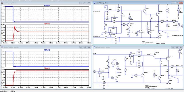
Oszilloskop-Messungen und Schaltpläne eines Netzteils
1.2ms 1.5ms 1.8ms 2.1ms 2.4ms 2.7ms 3.0ms 3.3ms i=500 set=.69 netzteil_komplett.asc LT1013 C6 20p BD139 V3 Q1 BUV48 29V D2 C5 LM3819 D1 R3 100nF R4 4R R16 BC546B Q5 R10 300R C3 0.47uF R11 10k R13 100R Q4 BC547B BD139 R14 10k OUT+ R19 Si4430DY R2 10k LT1013 C4 100nF R7 10k PWR+ GND R12 10k netzteil_dse-faq-neu.raw
in „Netzteilschaltung“ · Analoge Elektronik und Schaltungstechnik · · Screenshots
-
Datei
diff.txt
103E5000CAE0E8EBFFE30590002031F079D00016CE :103E5000CAE0E8EBFFE30590002031F079D00016CE :103E6000D1F3CA9591F0F5CF06EA8BD071D0E1F786 :103E6000D1F3CA9591F0F5CF06EA8BD071D0E1F786 :103E70000AEA87D06DD0F1F76BD0F1F3F101E89445 :103E70000AEA87D06DD0F1F76BD0F1F3F101E89445 :103E80000430F8F061F1063020F428BA27BA0C9417 :103E80000430F8F061F1063020F428BA27BA0C9417
in „UART Bootloader ATtiny13 - ATmega644“ · Projekte & Code ·
-
Datei
flash_dump_20141101_0x01eda2.diff
@ -2147,7 +2156,7 @@ 00008bc0 a4 44 68 2a 72 24 04 28 26 24 02 50 44 a0 24 22 |.Dh*r$.(&$.PD.$"| 00008bd0 22 80 52 44 41 80 72 24 24 a2 44 4a 26 72 24 84 |".RDA.r$$.DJ&r$.| 00008be0 a4 44 50 44 48 50 44 80 24 54 44 45 24 24 04 00 |.DPDHPD.$TDE$$..
in „Altera FPGA Flash (Active Serial) - Inhalt“ · FPGA, VHDL & Co. ·
-
Datei
WRundDTUadressenBereinigt.txt
:32 time:0 addr:0x0055 shiftbit9 60 71 70 63 01 (11/2/0) 37(63 70 71 60|72 22 84 12)00 f3[d3 b3]33 bd 73 aa 5f 7e c9 7e 5a 65 6d 24 - ch:0x03 size:32 time:0 addr:0x0055 shiftbit9 60 71 70 63 01 (11/2/0) 37(63 70 71 60|72 22 84 12)00 f3[d3 b3]3b ff f9 fb 5d db f6 ff ff ff bf ff - ch:0x03 size:32 time:
in „Wechselrichter Hoymiles HM-xxxx 2,4 GhZ Nordic Protokoll?“ · Mikrocontroller und Digitale Elektronik ·
-
Datei
decoded.txt
c5 6b 05 31 0a 5c e8 2c 47 e1 5d 41 30 12 b8 e7 c7 dc 88 02 b1 3f 8f b1 e0 c8 5e 05 97 39 3b 6c 38 24 e6 69 77 c6 29 a2 46 42 e1 f9 13 98 45 9c 48 6e e6 ee db 17 12 8d 8e d6 c6 90 17 f2 64 e5 23 be 9e 05 4d 16 85 86 cf fa 02 6e 54 fd ae 33 fe 2b 8d ce 07 a1 c1 03 6b cc 92 c4 bd e9 b3 9a 42 1f 08 75 5d
-
Datei
images.c
0xAB, 0x52, 0x03, 0x19, 0x85, 0x29, 0xAA, 0x52, 0x77, 0xAD, 0xFE, 0xDE, 0x31, 0x84, 0x28, 0x42, 0x24, 0x21, 0x65, 0x29, 0xAF, 0x73, 0xD9, 0xBD, 0xBD, 0xD6, 0x7C, 0xCE, 0xFF, 0xFF, 0xDB, 0xDE, 0xB4, 0x94, 0xB4, 0x94, 0xDB, 0xD6, 0xFF, 0xFF, 0xBC, 0xD6, 0x7F, 0xEF, 0xB8, 0xB5, 0xEB, 0x5A, 0xA6, 0x31,
in „STM32 24Bit Bmp nach 565RGB Format“ · Mikrocontroller und Digitale Elektronik ·
-
Datei
lcdtext.asm
0x00,0x80,0x41,0x41,0xC1,0x26,0x82,0x80,0x01,0x80,0x81,0x00,0x00,0x00,0x00,0x80,0x42,0x81,0x42,0x42,0x81,0x02,0x02,0x42,0x42,0x42,0x00,0x00,0x00,0x00,0x00,0x42 ; 0x3F .db 0x24,0x80,0x22,0x22,0x22,0x21,0x21,0x24,0x42,0x80,0x80,0x42,0x02,0x66,0x43,0x24,0x21,0x24,0x21,0x42,0x45,0x22,0x24,0x24,0x42,0x44,0x42,0x01,0x01,0x80,0x41,0x00 ; 0x5F .db 0x80,0x00,0x02,0x00,0x40,0x00,0x01,0x00,0x02,0x00,0x00,0x02,0x80,0x00,0x00,0x00,0x00,0x00,0x00,0x00,0x01,0x00,0x00,0x00,0x00,0x00,0x00,0x80,0x80,0x01,0x41,0x80
in „@ Benedikt K./"Displaybauer" - Homepage?“ · Mikrocontroller und Digitale Elektronik ·
-
Datei
lcdtext_12pxl_RS232_RX.asm
0x00,0x80,0x41,0x41,0xC1,0x26,0x82,0x80,0x01,0x80,0x81,0x00,0x00,0x00,0x00,0x80,0x42,0x81,0x42,0x42,0x81,0x02,0x02,0x42,0x42,0x42,0x00,0x00,0x00,0x00,0x00,0x42 ; 0x3F .db 0x24,0x80,0x22,0x22,0x22,0x21,0x21,0x24,0x42,0x80,0x80,0x42,0x02,0x66,0x43,0x24,0x21,0x24,0x21,0x42,0x45,0x22,0x24,0x24,0x42,0x44,0x42,0x01,0x01,0x80,0x41,0x00 ; 0x5F .db 0x80,0x00,0x02,0x00,0x40,0x00,0x01,0x00,0x02,0x00,0x00,0x02,0x80,0x00,0x00,0x00,0x00,0x00,0x00,0x00,0x01,0x00,0x00,0x00,0x00,0x00,0x00,0x80,0x80,0x01,0x41,0x80
in „Pollin Display Optrex F-51154NF-FW-AA“ · Mikrocontroller und Digitale Elektronik ·
-
Datei
disaess.txt
0x01001005 0a14 .word 0x00001017 0a18 .word 0x9e0e0760 0a1c .word 0xdc029e30 0a20 .word 0x16000a44 0a24 .word 0x9e0e0470 0a28 .word 0xdc029320 0a2c .word 0x160000bd 0a30 .word 0x9c1807a4 0a34 .word 0x9c1807e0 0a38 .word 0xdc03a540 0a3c .word 0x160003d2 0a40 .word 0x40000613 0a44 .word 0x16000184 0a48 .
in „Vermutliches TMS320C6xx-Binary disassemblieren“ · Digitale Signalverarbeitung / DSP / Machine Learning ·
-
Datei
set65_eprommer_software_hexdump.txt
EE 09 40 85 EE A2 E6 20 17 FA E160: B0 9A 20 A8 E3 F0 0A C9 42 D0 48 20 FF E1 4C 62 E170: E1 A2 18 BD 19 02 9D 00 02 CA 10 F7 24 EE 50 0A E180: A5 E6 8D 11 02 A5 E7 8D 12 02 20 04 E4 D0 24 20 E190: FF E1 A5 EE 29 20 F0 18 AD 0D 02 C9 43 D0 11 AD E1A0: 0E 02 C9 4F D0 0A AD 0F 02 C9 4D D0 03 6C 11 02 E1B0
in „CT SET 65 Einplatinencomputer“ · Mikrocontroller und Digitale Elektronik ·
-
PDF
An_Efficient_Analytic_Signal_Generator.pdf
, v 2a its i t and q t channels have identi- 1 cal frequency magnitude responses; sin2 p 3v2 v1 2a 24 , v 2a # v # v 1a b 4a 1 r 1 1 however that scheme does not exhibit a H v 5g 1, v 1a # v # v 2a (1) linear-phase frequency response.) Since 1 2 the absolute phase associated with a 2 p 3 1 24 cos b 4a
in „Junge Menschen für den Amateurfunk begeistern“ · HF, Funk und Felder ·
-
PDF
LED_Power_Supply_Cheng_Liang_P360W24V.pdf
0,04 @ 120Hz NEUT U þÿ1µF, 105K, X2, 310VA6C80k 1 4 F8A/250V ZNR (MOV) CY4 2.2nF 222M NDF CT7Y2300VAC BD1 C? 3 STY GBU808 800V/8A R? 150k, 1/2W? þÿ680µF 250VDC 105°C Oxcorun F(M) þÿgemessen: C=530µF D=0,04 @ 120Hz CY1 10nF 1kV PRI_LO GND 0VDC PRI_HI R? D? R? R? +24V R? D? 330k, 1/2W 2 10R, 1/2W 10R, 1/2W
in „Halbbrücken-Gegentaktwandler Ansteuerung“ · Analoge Elektronik und Schaltungstechnik ·
-
Datei
pinout.h
pin 6//2 #define sensor4_port D//20pin20-Qmidea #define sensor4_pin 4//2 //output //wp p1 ww wz kü bd lu no le //d7 d6 d5 b0 b1 d0 d1 d2 d3 //c2 c3 c4 c5 c6 c7 ++ -- a2 a7 a6 //b0 b1 d0 d5 d6 d7 ++ -- d1 d2 d3 /*#define out1_port C #define out1_pin 7 #define out2_port C #define out2_pin 6 #define out3
in „Header Datei für Konfiguration erstellen“ · Mikrocontroller und Digitale Elektronik ·
