-
Datei
_4.0_User_Setup.h
touch screen //#define TFT_WR PIN_D2 // Write strobe for modified Raspberry Pi TFT only // ###### FOR ESP8266 OVERLAP MODE EDIT THE PIN NUMBERS IN THE FOLLOWING LINES ###### // Overlap mode shares the ESP8266 FLASH SPI bus with the TFT so has a performance impact // but saves pins for other functions. /
in „Esp32 Display“ · Mikrocontroller und Digitale Elektronik ·
-
Datei
PuttyLog.txt
server) (WICON 04d) var_send_buf: expected ESP8266_OK, got 11 read rtc: Sa 2017-12-23 15:58:45 DS18xxx temperature: 25 RTC temperature: 21 overlay icon Advent4 --> icon "wc12h-icon.txt","Advent4"<0d><0a> var_send_buf: expected ESP8266_OK, got 15
-
Datei
ERR09.txt
google.ch:80 [HTTP-Client] sending request header ----- GET / HTTP/1.1 Host: google.ch User-Agent: ESP8266HTTPClient Connection: close Accept-Encoding: identity;q=1,chunked;q=0.1,*;q=0 ----- [HTTP-Client][handleHeaderResponse] RX: 'HTTP/1.1 301 Moved Permanently' [HTTP-Client][handleHeaderResponse] RX
in „ESP8266 - Arduino - HTTP Get, ESP stürzt ab.“ · Mikrocontroller und Digitale Elektronik ·
-
Datei
ESP8266_Robi_v2.ino
************** //*********************************************************************** #include <ESP8266WiFi.h> #include <ESP8266WebServer.h> #include <WiFiClient.h> #include <ESP8266mDNS.h> #include <ESP8266HTTPUpdateServer.h> //*********************************************************************
in „Automower G3 mit USB Diagnoseport fernsteuern?“ · Mikrocontroller und Digitale Elektronik ·
-
Datei
kompl.Sketch.txt
[c] /* Generic ESP8266 Modul sketch_mar27c.ino aus BasicHTTPClient.ino Created on: 27.03.2024 liest den Status aus Shelly 3EM, filtert nach "POWER",ermittelt den Strom eines Moduls, schaltet die notwendige/zulässige Anzahl Module zu oder ab, und funkt das Ergebnis an einen ESP01 zur Anzeige am Monitor. */ #include <ESP8266WiFi.h> #include <ESP8266WiFiMulti.h> #include <ESP8266HTTPClient.h> #include <WiFiClient.h> #include <espnow.h> ESP8266WiFiMulti WiFiMulti; // REPLACE
in „ESPNOW senden mit ESP12 geht schief, warum ?“ · Mikrocontroller und Digitale Elektronik ·
-
Datei
logs_hz-m404_logs_2023-01-20_E.txt
:295]: Log Baud Rate: 0 [18:57:39][C][logger:296]: Hardware UART: UART0 [18:57:39][C][uart.arduino_esp8266:102]: UART Bus: [18:57:39][C][uart.arduino_esp8266:103]: TX Pin: GPIO1 [18:57:39][C][uart.arduino_esp8266:104]: RX Pin: GPIO3 [18:57:39][C][uart.arduino_esp8266:106]: RX Buffer Size: 256 [18:57:39][C][uart.arduino_esp8266:108]: Baud Rate: 2400 baud [18:57:39][C][uart.arduino_esp8266:109]: Data Bits: 8 [18:57:39][C][uart.arduino_esp8266:110]: Parity: NONE [18:57:39][C][uart.arduino_esp8266:111]: Stop bits: 1 [18:57
-
Datei
user_main.c
**************************************************************************** Testprogramm IRMP für ESP8266 16.11.2015 Wolfgang Strobl, Bonn IRMP adaptiert für den ESP8266, getestet mit einem MOD-WIFI-ESP8266-DEV auf einem ESP8266-EVB Evaluation board. https://www.olimex.com/Products/IoT/ESP8266-EVB/
in „IRMP mit ESP8266“ · Mikrocontroller und Digitale Elektronik ·
-
Datei
sketch_mar27c.ino
/* Generic ESP8266 Modul sketch_mar27c.ino aus BasicHTTPClient.ino Created on: 27.03.2024 liest den Status aus Shelly 3EM, filtert nach "POWER",ermittelt den Strom eines Moduls, schaltet die notwendige/zulässige Anzahl Module zu oder ab, und funkt das Ergebnis an einen ESP01 zur Anzeige am Monitor. */ #include <ESP8266WiFi.h> #include <ESP8266WiFiMulti.h> #include <ESP8266HTTPClient.h> #include <WiFiClient.h> #include <espnow.h> ESP8266WiFiMulti WiFiMulti; // REPLACE
in „ESPNOW senden mit ESP12 geht schief, warum ?“ · Mikrocontroller und Digitale Elektronik ·
-
Bild
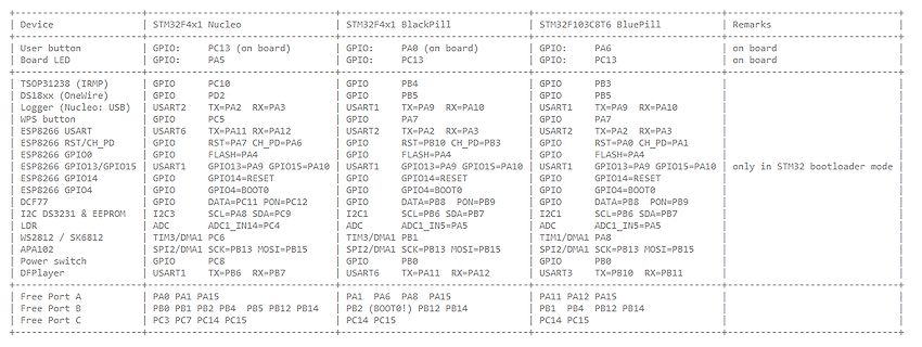
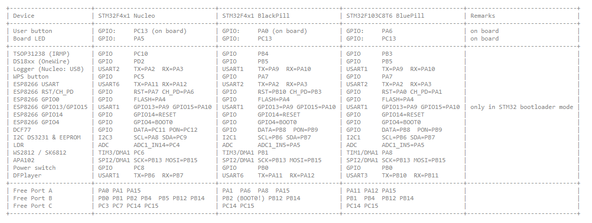
Tabelle mit Pinbelegungen verschiedener Mikrocontroller-Boards
| GPIO: TX=PA9 RX=PA10 | USART1: TX=PA9 RX=PA10 | WPS button | GPIO: PC5 | GPIO: PA7 | GPIO: PA7 | ESP8266 USART | GPIO: TX=PA11 RX=PA12 | USART2: TX=PA2 RX=PA3 | USART2: TX=PA2 RX=PA3 | ESP8266 GPIO | GPIO: RST=CH_PD=PA4 | GPIO: RST=PB10 CH_PD=PB3 | GPIO: RST=PA0 CH_PD=PA1 | ESP8266 GPIO | GPIO: FLASH=PA4 | GPIO: FLASH=PA4 | GPIO: FLASH=PA4 | ESP8266 GPIO | GPIO: GPIO13/GPIO15 | GPIO: GPIO13=PA9 GPIO15=PA10 | USART1: GPIO13=PA9 GPIO15=PA10 | only in STM32 bootloader mode ESP8266 GPIO | GPIO: GPIO14=RESET | GPIO: GPIO14=RESET | USART1: GPIO14
in „WordClock mit WS2812“ · Projekte & Code · · Screenshots
-
Datei
Log_Startup.txt
online current eeprom version: 0xff007e00 updating EEPROM to version 0x00020900... done DFPLAYER LOGGER ESP8266 LOGGER read rtc: Sa 2018-07-28 23:05:01 read rtc: Sa 2018-07-28 23:05:01 esp8266 now up (- setup UDP) (- local port: 2421) (- setup server UDP) (- local port: 2424) (FIRMWARE 2.9.2) (- tables found
-
Datei
PWMAUDIO.ino
#include <stdint.h> #include <WebSocketsServer.h> #include <ESP8266WiFi.h> #include <ESP8266WebServer.h> #include <ESP8266mDNS.h> #include "FS.h" #include <Arduino.h> #include "interrupts.h" extern "C" { #include "user_interface.h" #include "ets_sys.h" } //define
in „PWM Audio mit ESP8266, schlechte Qualitaet, -Arduino“ · Mikrocontroller und Digitale Elektronik ·
-
Bild
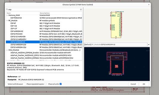
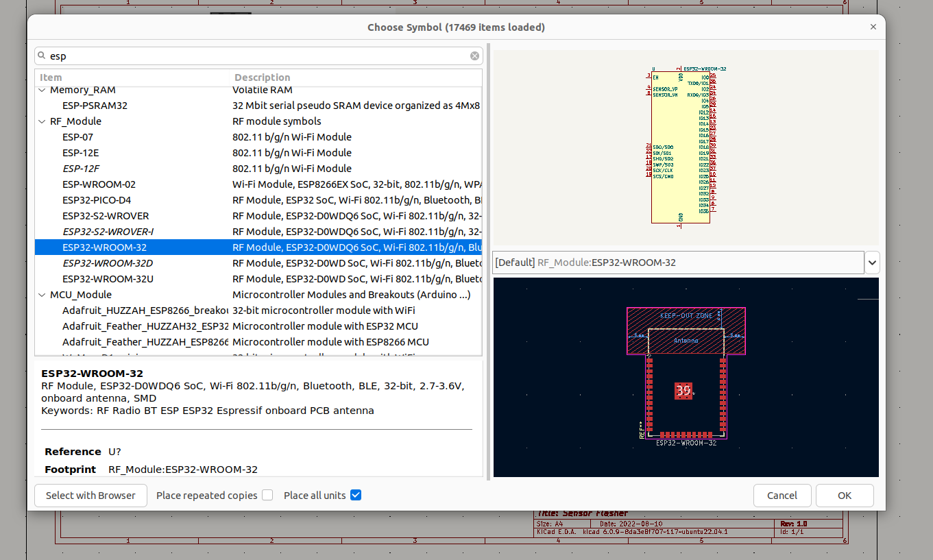
Software-Fenster mit Bauteil-Auswahlliste und PCB-Layout
Choose Symbol (17469 Items loaded) q esp Item Description Volatile RAM Memory_RAM ESP-PSRAM32 RF_Module ESP-07 802.11 b/g/n Wi-Fi Module ESP-12E 802.11 b/g/n Wi-Fi Module ESP-12F 802.11 b/g/n Wi-Fi Module ESP-WR00-02 Wi-Fi Module, Bluetooth
in „Design wiederverwenden unter KiCAD“ · Platinen · · Screenshots
-
PDF
Fehlermeldungen.pdf
reference to `esp_now_init()' D:\Eigene Anwendungen\Arduino_neu\ESP_NOW\Sender/Sender.ino:46: undefined reference to `esp_now_set_self_role(unsigned char)' D:\Eigene Anwendungen\Arduino_neu\ESP_NOW\Sender/Sender.ino:
in „nodemcu mit espnow verbinden“ · Mikrocontroller und Digitale Elektronik ·
-
Bild
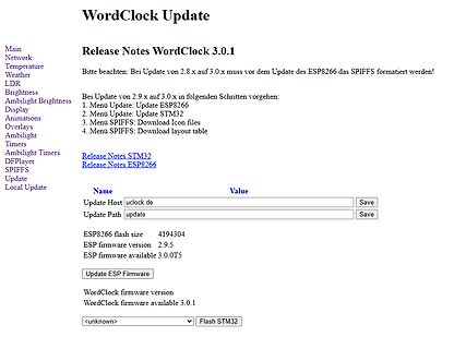
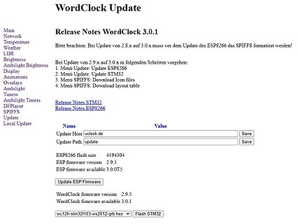
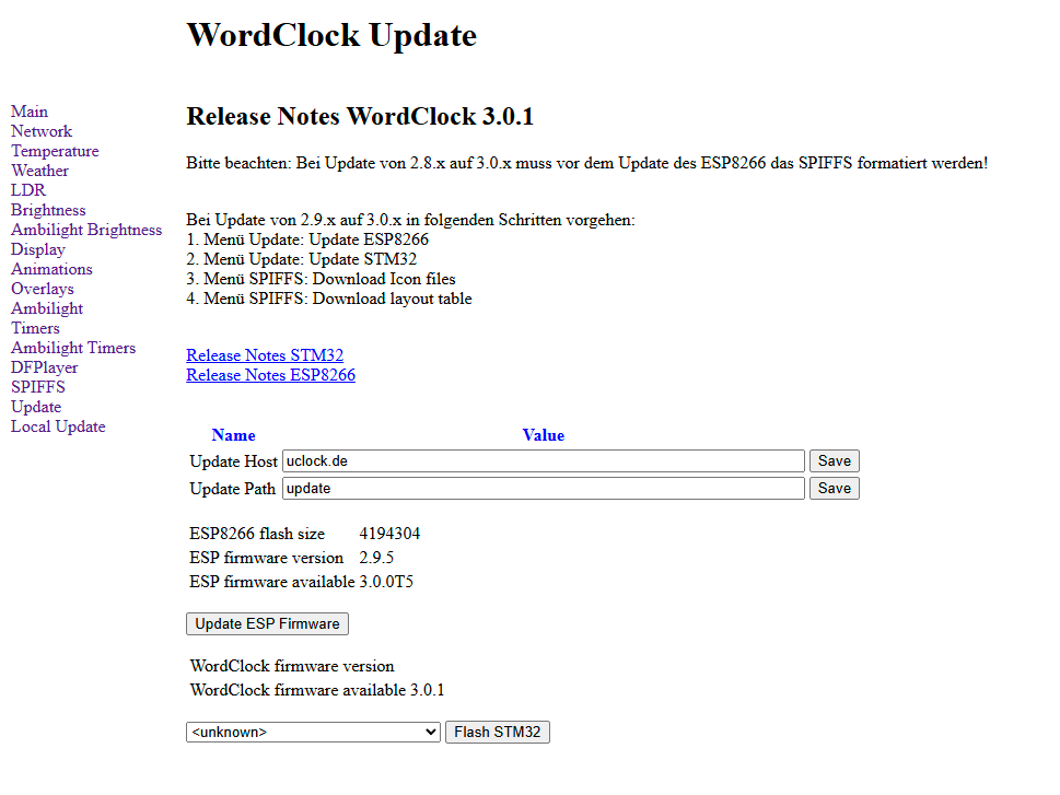
Webinterface WordClock Update Release Notes
Release Notes WordClock 3.0.1 Bitte beachten: Bei Update von 2.8.x auf 3.0.x muss vor dem Update des ESP8266 das SPIFFS formatiert werden! Bei Update von 2.9.x auf 3.0.x in folgenden Schritten vorgehen: 1. Menü Update: Update ESP8266 2. Menü Update: Update STM32 3. Menü SPIFFS: Download Icon files 4. Menü SPIFFS: Download layout table Release Notes STM32 Release Notes ESP8266 Name Value Update Host uclock.de Save Update Path update Save ESP8266 flash size 4194304 ESP firmware version 2.9.5 ESP firmware available 3.0.0T5 Update ESP Firmware WordClock firmware version
in „WordClock mit WS2812“ · Projekte & Code · · Screenshots
-
Bild
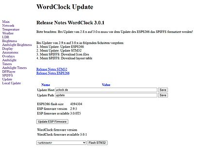
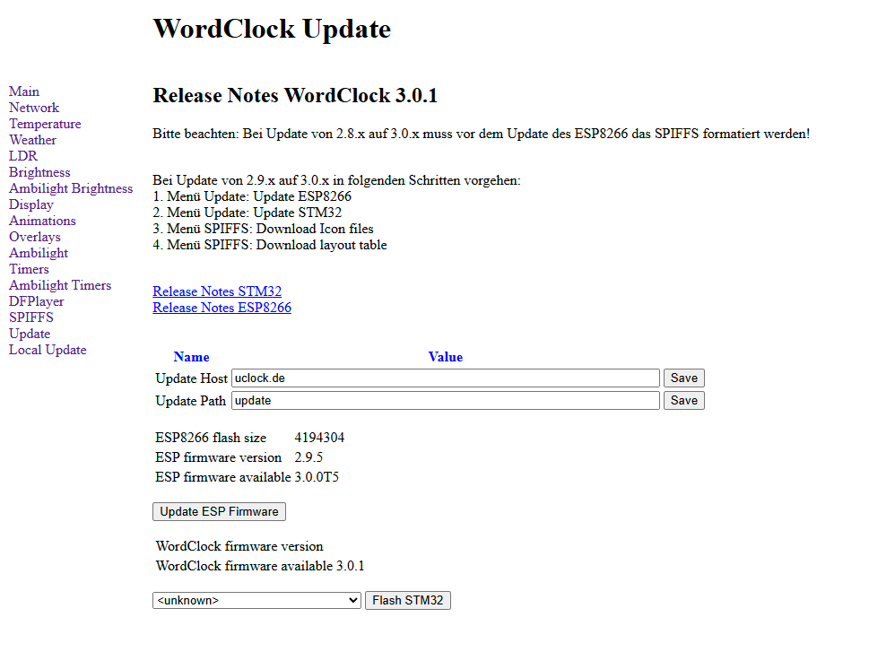
Webinterface WordClock Update Release Notes
Release Notes WordClock 3.0.1 Bitte beachten: Bei Update von 2.8.x auf 3.0.x muss vor dem Update des ESP8266 das SPIFFS formatiert werden! Bei Update von 2.9.x auf 3.0.x in folgenden Schritten vorgehen: 1. Menü Update: Update ESP8266 2. Menü Update: Update STM32 3. Menü SPIFFS: Download Icon files 4. Menü SPIFFS: Download layout table Release Notes STM32 Release Notes ESP8266 Name Value Update Host uclock.de Save Update Path update Save ESP8266 flash size 4194304 ESP firmware version 2.9.5 ESP firmware available 3.0.0T5 Update ESP Firmware WordClock firmware version
in „WordClock mit WS2812“ · Projekte & Code · · Screenshots
-
Datei
howto.txt
dann das ESP8266-Modul in den Flash-Modus und verbindet dann die beiden UARTs softwaremäßig 1:1, d.h. die Daten werden vom USB-Anschluss transparent an das ESP8266-Modul weitergegeben. Nun startet man das Programm esp8266_flasher.exe und wählt durch Klick auf die Schaltfläche Bin die Datei "v1.2-ESP-WordClock.bin" aus Außerdem muss der COM-Port an den tatsächlichen Anschluss angepasst werden. Dann "Download" betätigen
-
Datei
Program.txt
*/ #include "DHT.h" #define DHTPIN 2 // Digital pin connected to the DHT sensor // Feather HUZZAH ESP8266 note: use pins 3, 4, 5, 12, 13 or 14 -- // Pin 15 can work but DHT must be disconnected during program upload. // Uncomment whatever type you're using! //#define DHTTYPE DHT11 // DHT 11 //#define
in „Leseprobleme mit dem DHT21 an einem D1 Mini V3“ · Mikrocontroller und Digitale Elektronik ·
-
Bild
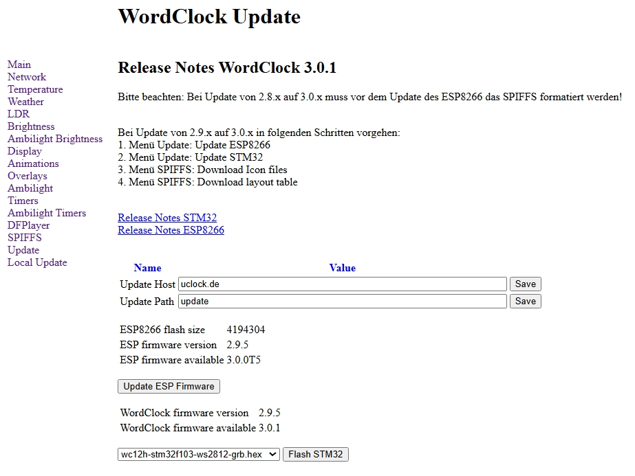
Software-Update-Interface für WordClock 3.0.1
Release Notes WordClock 3.0.1 Bitte beachten: Bei Update von 2.8.x auf 3.0.x muss vor dem Update des ESP8266 das SPIFFS formatiert werden! Menü Update: Update ESP8266 Menü Update: Update STM32 Menü SPIFFS: Download Icon files Menü SPIFFS: Download layout table Release Notes STM32 Release Notes ESP8266 Update Host uclock.de Update Path update ESP8266 flash size 4194304 ESP firmware version 2.9.5 ESP firmware available 3.0.0T5 WordClock firmware version 2.9.5 WordClock firmware available 3.0.1 Flash STM32
in „WordClock mit WS2812“ · Projekte & Code · · Screenshots
-
PDF
Platine_4_Kanal.pdf
I2C-SCL A5 AD-Wandler, ggf. LCD und/oder LEDs SS oder D10 Select für SPI (W5500) GPIO0 Statusmeldung vom ESP8266 incl. LED gegen 3V3 MOSI oder D11 MOSI für SPI oder TxD Sendedaten zum ESP8266 (Spannungsteiler) MISO oder D12 MISO für SPI oder RxD Empfangsdaten vom ESP8266 SCK oder D13 Clock für SPI RST Reset zum ESP8266 (Diode in Reihe)
in „Hutschienen Arduino“ · Mikrocontroller und Digitale Elektronik ·
-
Datei
Shelly_WPcontrol.ino
#include <Arduino.h> #include <ArduinoJson.h> #include <ESP8266WiFi.h> #include <ESP8266HTTPClient.h> #include <ESP8266WebServer.h> #include <ESP8266HTTPUpdateServer.h> #define has_ntp #if defined has_ntp #define ntptimeoffset 7200 // 2 h in sec #include <NTPClient.h> #include <WiFiUdp.h> WiFiUDP ntpUDP; NTPClient timeClient(ntpUDP); #endif ESP8266WebServer server(80); ESP8266HTTPUpdateServer httpUpdater; const char *ssid = "FSM"; const char *password = "0101010101"; String Shelly_IP = "192.168.178.47"; String WP_IP = "192.168.178.66"; int8
-
Datei
ESP8266_WiFI_UDP_Server_OLED.ino
/***************************************** ****************************************** ** ** ** ESP8266_WiFI_UDP_Server_OLED.ino ** ** ** ****************************************** *****************************************/ #include <Arduino.h> #include <ESP8266WiFi.h> #include <WiFiUDP.h> #include
in „UDP-Netzwerke(l)n mit kleinen Mikrocontrollern und WizNet W5100/W5500“ · Mikrocontroller und Digitale Elektronik ·
-
Datei
User_Setup.h
touch screen //#define TFT_WR PIN_D2 // Write strobe for modified Raspberry Pi TFT only // ###### FOR ESP8266 OVERLAP MODE EDIT THE PIN NUMBERS IN THE FOLLOWING LINES ###### // Overlap mode shares the ESP8266 FLASH SPI bus with the TFT so has a performance impact // but saves pins for other functions. It
in „Powerpins am ESP32-DevKitC, WDT_RTC_RESET“ · Mikrocontroller und Digitale Elektronik ·
-
Datei
MYSENSORS_GatewayClient_WORK_V3.ino
blink on error during transmission error or recieve crc error * * See http://www.mysensors.org/build/esp8266_gateway for wiring instructions. * nRF24L01+ ESP8266 * VCC VCC * CE GPIO4 * CSN/CS GPIO15 * SCK GPIO14 * MISO GPIO12 * MOSI GPIO13 * * Not all ESP8266 modules have all pins available on their external
in „String Array verarbeiten / Arduino“ · Mikrocontroller und Digitale Elektronik ·
-
Datei
Temperatur_DS18B20.ino
and OLED driver written by http://stefanfrings.de/ */ #include <SPI.h> #include <Wire.h> #include <ESP8266WiFi.h> //ESP8266 Core WiFi Library #include <ESP8266WiFiMulti.h> //ESP8266 Core WiFi Library #include <DNSServer.h> #include <ESP8266WebServer.h> //Local WebServer #include <NTPClient.h> #include <WiFiUdp.h> #include <WiFiManager.h> // https://github.com/tzapu/WiFiManager #include <ESP8266HTTPClient.h> #include <ESP8266httpUpdate.h> #include <WiFiClient.h> #include <OneWire.h> #include <DallasTemperature.h> #include "global.h" #include "configFS.h" #include "WebClient.h" #ifdef OLED_CONNECT
in „ESP Temperaturmodul mit DS18B20 und Web-Ansicht“ · Mikrocontroller und Digitale Elektronik ·
-
Bild
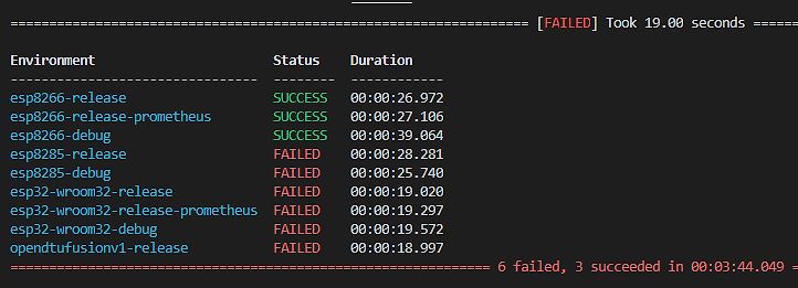
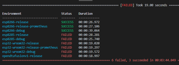
Statusliste eines Build-Prozesses
[FAILED] Took 19.00 seconds Environment Status Duration esp8266-release SUCCESS 00:00:26.972 esp8266-release-prometheus SUCCESS 00:00:27.106 esp8266-debug SUCCESS 00:00:39.064 esp8285-release FAILED 00:00:28.281 esp8285-debug FAILED 00:00:25.740 esp32-wroom32-release FAILED 00:00:19.020 esp32-wroom32-release-prometheus FAILED 00:00:19.297 esp32-wroom32-debug FAILED 00:00:19.572 opendtufusionv1-release FAILED 00:00:18.997 6 failed, 3 succeeded in 00:03:44.049
in „Wechselrichter Hoymiles HM-xxxx 2,4 GhZ Nordic Protokoll?“ · Mikrocontroller und Digitale Elektronik · · Screenshots
-
Datei
PowerReglerDTZ.ino
without approval of us (me). **/ //#define DEBUG_PAYLOAD //#define DEBUG_VALUE #define OTA_on #include <ESP8266WiFi.h> //ESP8266 Core WiFi Library #include <ESP8266WiFiMulti.h> //ESP8266 Core WiFi Library #include <DNSServer.h> #include <ESP8266WebServer.h> //Local WebServer #include "configPWR.h" #include
in „Schaltsteckdose für StromLog ESP“ · Mikrocontroller und Digitale Elektronik ·
-
Datei
dash_button.ino
#include <Arduino.h> #include <ESP8266WiFi.h> #include <ESP8266WiFiMulti.h> #include <ESP8266HTTPClient.h> // wenn aktiv: Meldungen per Serial #define SERIAL // wenn auskommentiert: delay() // wenn aktiv: deep sleep nutzen (Hardwaremodifikation
in „ESP8266-03 stürzt ab, Arduino IDE“ · Mikrocontroller und Digitale Elektronik ·
-
Bild
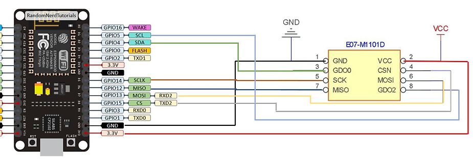
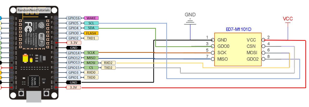
Verdrahtung zwischen ESP32 und E07-M1101D Modul
RandomNerdTutorials, ESP32, WROOM, GPIO16 WAKE, GPIO5 SCL, GPIO4 SDA, GPIO0 FLASH, GPIO2 TXD1, 3.3V, GND, GPIO14 SCLK, GPIO12 MISO, GPIO13 MOSI, GPIO15 CS, GPIO3 RXD2, GPIO1 TXD0, GPIO1 RXD0, GND, 3.3V, E07-M1101D, GND, VCC, 1 GND, 2 VCC, 3 CSN, 4 CSN, 5 SCK, 6 MOSI, 7 MISO, 8 GDO2, GDO0
in „Jarolift TDEF“ · Haus & Smart Home · · Diagramme
-
Bild
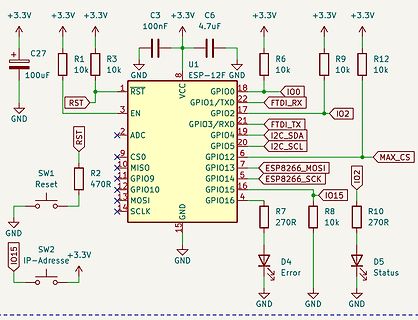
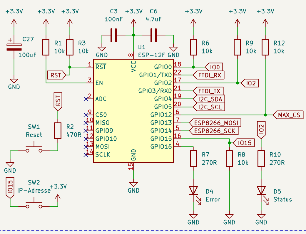
Schaltplan eines ESP-12F Mikrocontrollers
+3.3V, C27, 100uF, R1, 10k, R3, 10k, C3, 100nF, U1, ESP-12F, GND, R6, 10k, R9, 10k, R12, 10k, I00, FTDI_RX, I02, FTDI_TX, I2C_SDA, I2C_SCL, MAX_CS, I02, I015, R10, 270R, D5, Status, R8, 10k, R7, 270R, D4, Error, GND, GPIO16, GPIO15, GPIO14, GPIO13, ESP8266_SCK, ESP8266_MOSI, GPIO12, GPIO05, GPIO04, GPIO03, GPIO02, GPIO01/TXD, RST, EN, ADC, CS0, MISO, GPIO09, GPIO10, MOSI, SCLK, SW1, Reset, R2, 470R, SW2, IP-Adresse, +3.3V
in „I2C RTC+EEPROM mit ESP8266. Mal funktionierts mal nicht“ · Mikrocontroller und Digitale Elektronik · · Schaltpläne
-
Datei
DTZ_Logger_WLAN.ino
/** * DTZ 541 Logger **/ #include <ESP8266WiFi.h> //ESP8266 Core WiFi Library #include <ESP8266WiFiMulti.h> //ESP8266 Core WiFi Library #include <DNSServer.h> #include <ESP8266WebServer.h> //Local WebServer #include <NTPClient.h> #include <WiFiManager.h> // https://github.com/tzapu/WiFiManager #include <ESP8266HTTPClient.h> #include <WiFiClient.h> ADC_MODE(ADC_VCC); #define BoardTaster 0 #define MESZ 0 // summer-time = 1 else winter-time = 0 #define MaxBuffer 552 // maximum buffe for received bytes unsigned
in „DTZ541 mMe Datenlogger mit ESP (WEB-Sicht)“ · Mikrocontroller und Digitale Elektronik ·
-
Datei
200311mi2200.ino
#include <ESP8266WiFi.h> #include <WiFiClient.h> #include <ESP8266WebServer.h> #include <ESP8266mDNS.h> #include <Wire.h> #ifndef STASSID #define STASSID "gs23w" //Netzwerkname eingeben FabLab_Guest #define STAPSK
in „Neu bei microcontoller_net und schon eine Frage“ · Mikrocontroller und Digitale Elektronik ·
-
Datei
DTZ_Logger_WLAN.ino
/** * DTZ 541 Logger * Version 0.2 * 25.11.2020 P. Rebesky **/ #include <ESP8266WiFi.h> //ESP8266 Core WiFi Library #include <ESP8266WiFiMulti.h> //ESP8266 Core WiFi Library #include <DNSServer.h> #include <ESP8266WebServer.h> //Local WebServer #include <NTPClient.h> #include <WiFiManager.h> // https://github.com/tzapu/WiFiManager #include <ESP8266HTTPClient.h> #include <WiFiClient.h> ADC_MODE(ADC_VCC); #define BoardTaster 0 #define MESZ 0 // summer-time = 1 else winter-time = 0 #define MaxBuffer 552 // maximum buffe for received bytes //const
in „DTZ541 mMe Datenlogger mit ESP (WEB-Sicht)“ · Mikrocontroller und Digitale Elektronik ·
-
Datei
Sender.ino
Taster // Master in einem eigenen WLAN // Steuert an einem WeMos D1 mini einen LED Streifen #include <ESP8266WiFi.h> #include <WiFiClient.h> #include <WiFiServer.h> #include <WiFiUdp.h> #include <ESP8266mDNS.h> #include <ESP8266WebServer.h> char *ssid = "NETZWERKNAME"; char *password = "NETZWERKPASSWORT
in „Daten zwischen zwei ESPs in Echtzeit übertragen“ · Mikrocontroller und Digitale Elektronik ·
-
Datei
Sender.ino
Taster // Master in einem eigenen WLAN // Steuert an einem WeMos D1 mini einen LED Streifen #include <ESP8266WiFi.h> #include <WiFiClient.h> #include <WiFiServer.h> #include <WiFiUdp.h> #include <ESP8266mDNS.h> #include <ESP8266WebServer.h> char *ssid = "NETZWERKNAME"; char *password = "NETZWERKPASSWORT
in „Daten zwischen zwei ESPs in Echtzeit übertragen“ · Mikrocontroller und Digitale Elektronik ·
-
Datei
WLAN-Server_LED_Steuerung.ino
192.168.178.53/schalten/?wert=status1 http://192.168.178.53/schalten/?wert=DeepSleep30Sek #include <ESP8266WiFi.h> #include <ESP8266WebServer.h> #include <ESP8266WiFiMulti.h> // fuer I2C #include <Wire.h> //der pcf8574A hat andere Adresse als der pcf8574: //pcf8574 : 0 1 0 0 A2 A1 A0 R/W => wenn alle
in „LED-Steuerung mit WLAN-Server, bistablen Relais und ZeroCrossSwitching“ · Projekte & Code ·
-
Datei
http.cpp
------------------------------------------------------------------------------ * possible modes of ESP8266 *-------------------------------------------------------------------------------------------------------------------------------------- */ #define ESP8266_CLIENT_MODE 0 #define ESP8266_AP_MODE 1 #define ESP8266_MAX_FIRMWARE_SIZE 16 #define ESP8266_MAX_ACCESSPOINT_SIZE 32 #define ESP8266_MAX_IPADDRESS_SIZE 16 #define ESP8266_MAX_HTTP_GET_PARAM_SIZE 256 #define ESP8266_MAX_CMD_SIZE 32 #define ESP8266_MAX_TIME_SIZE
-
PDF
UserManualForTTL-WiFi.pdf
2017 Page 28 ® DOIT.AM User Manual for TTL-WiFi DT-06 5mm 5mm 6.6mm 1 5 1 1 4 mainboard 2 1 3 3 1 2 4 ESP‐M2 1 1 5 16 1 0 6 9 7 8 L S TTL‐WiFi S W W 2 1 1 2 3 4 5 6 Figure 8.1 Scheme 1 6.6mm 1 5 1 1 4 2 1 3 3 4 ESP‐M2 1 2 1 1 5 16 1 0 Mainboard 6 9 7 8 L S TTL‐WiFi S W W 2 1 1 2 3 4 5 6 Fig. 8.2 Scheme2
-
Datei
ERR03.txt
ImageConvert/pushData.php?nodeID=1&values=12.5;14.7;36.5 HTTP/1.1 Host: srv12.blselectronics.ch User-Agent: ESP8266HTTPClient Connection: close Accept-Encoding: identity;q=1,chunked;q=0.1,*;q=0 ----- [HTTP-Client][handleHeaderResponse] RX: 'HTTP/1.1 200 OK' [HTTP-Client][handleHeaderResponse] RX: 'Date: Wed,
in „ESP8266 - Arduino - HTTP Get, ESP stürzt ab.“ · Mikrocontroller und Digitale Elektronik ·
-
Datei
wifi-serial-1.ino
// from // https://atadiat.com/en/e-esp8266-esp32-wifi-serial-bridge-converter/ /**** This version is ported by Atadiat to work on ESP8266 (tested on NodeMCU 1.0) ****/ /**** Porting was done by Yahya Tawil****/ // ESP32 WiFi <-> 3x UART
in „serielle Funkbrücke“ · Mikrocontroller und Digitale Elektronik ·
-
PDF
ESPIO-Schaltung.pdf
. . . . . . . . . . I/O HV.COM WIFI.IO#15 GPIO15/TXD2/RTS0 F F F F F F F F F F I I I I I I I I I I ESP8266 (ESP-07) WW W W W W W WWW GND 3 3 ⚡ + HV.COM 5 R1 L1 + HV.N DC1 1 2 8C CRF253-4 7 BLM31PG601 V WiFi & I/O Seite: 2 von 2 D K 1 AC1 +VO 4 RF1/PWR 4 1 C3 +C5 C7 D + C8 C9 C10 WiFi: ESP8266 (ESP-07
-
Datei
DTZ_Logger_WLAN.ino
/** * DTZ 541 Logger * Version 0.9 * 10.12.2020 P. Rebesky **/ #include <ESP8266WiFi.h> //ESP8266 Core WiFi Library #include <ESP8266WiFiMulti.h> //ESP8266 Core WiFi Library #include <DNSServer.h> #include <ESP8266WebServer.h> //Local WebServer #include <NTPClient.h> #include <WiFiManager.h> // https://github.com/tzapu/WiFiManager #include <ESP8266HTTPClient.h> #include <WiFiClient.h> ADC_MODE(ADC_VCC); #define BoardTaster 0 #define MESZ 0 // summer-time = 1 else winter-time = 0 #define MaxBuffer 552 // maximum buffe for received bytes #define
in „DTZ541 mMe Datenlogger mit ESP (WEB-Sicht)“ · Mikrocontroller und Digitale Elektronik ·
-
Datei
makefile-Error.txt
uart.c In file included from driver/uart.c:12:0: driver/uart.c: In function 'uart_config': c:/Espressif/ESP8266_SDK/include/ets_sys.h:61:5: error: implicit declaration of function 'ets_isr_attach' [-Werror=implicit-function-declaration] ets_isr_attach(ETS_UART_INUM, (func), (void *)(arg)) ^ driver/uart.c:
in „IDE für ESP8266 mit vielen Example“ · Mikrocontroller und Digitale Elektronik ·
-
Datei
ESP_Webserver_HTTP11_Original_.ino
/*-------------------------------------------------- HTTP 1.1 Webserver for ESP8266 for ESP8266 adapted Arduino IDE Stefan Thesen 04/2015 Running stable for days (in difference to all samples I tried) Does HTTP 1.1 with defined connection closing. Reconnects in case of lost WiFi
in „esp8266 - Farbdarstellung“ · Mikrocontroller und Digitale Elektronik ·
-
Datei
PowerReglerDTZ.ino
OTA_on #define ESPRAM "R1M" // for 1 MB memory //#define ESPRAM "R2M" // for 2 MB memory #include <ESP8266WiFi.h> //ESP8266 Core WiFi Library #include <ESP8266WiFiMulti.h> //ESP8266 Core WiFi Library #include <DNSServer.h> #include <ESP8266WebServer.h> //Local WebServer #include "configPWR.h" #include
in „Schaltsteckdose für StromLog ESP“ · Mikrocontroller und Digitale Elektronik ·
-
Datei
arduinopreferences.txt
board=esp32doit-devkit-v1 boardsmanager.additional.urls=https://dl.espressif.com/dl/package_esp32_index.json,http://arduino.esp8266.com/stable/package_esp8266com_index.json build.verbose=true build.warn_data_percentage
in „Fehlersuche ESP32, der mit Hilfe der Arduino IDE programmiert wurd“ · Mikrocontroller und Digitale Elektronik ·
-
Datei
StromLog_Open.ino
using is forbidden without approval of us (me). **/ //#define crc16check #define OTA_on #include <ESP8266WiFi.h> //ESP8266 Core WiFi Library #include <ESP8266WiFiMulti.h> //ESP8266 Core WiFi Library #include <DNSServer.h> #include <ESP8266WebServer.h> //Local WebServer #include <ESP8266HTTPClient.h>
in „Digitale Stromzähler auslesen und in DB speichern“ · Mikrocontroller und Digitale Elektronik ·
-
Datei
ok180121.ino
/* * ESP8266 Servo Motor Control With Web Server * https://circuits4you.com */ #include <FS.h> //Include File System Headers #include <ESP8266WiFi.h> #include <WiFiClient.h> #include <ESP8266WebServer.h> #include
in „expected initializer before progmem - Problem“ · Mikrocontroller und Digitale Elektronik ·
-
Datei
Sender.ino
/* Rui Santos Complete project details at https://RandomNerdTutorials.com/esp-now-one-to-many-esp8266-nodemcu/ Permission is hereby granted, free of charge, to any person obtaining a copy of this software and associated documentation files. The above copyright notice and this

in „nodemcu mit espnow verbinden“ · Mikrocontroller und Digitale Elektronik ·
-
Datei
ESP8266_Robi_v2.ino
************** //*********************************************************************** #include <ESP8266WiFi.h> #include <ESP8266WebServer.h> //*********************************************************************** //*** Deklaration ***************************************************** //*********
in „Automower G3 mit USB Diagnoseport fernsteuern?“ · Mikrocontroller und Digitale Elektronik ·
-
Datei
platformio.ini
[platformio] default_envs = esp01 [env] platform = espressif32 framework = arduino build_flags = -Wall -Werror -DLOG_LEVEL=LOG_LEVEL_DEBUG monitor_speed = 115200 [env:esp32dev] board = esp32dev build_flags = ${env.build_flags} [env:esp12] platform = espressif8266 board = esp12e build_flags = ${env.build_flags} [env:esp01] platform = espressif8266 board = esp01 build_flags = ${env.build_flags}
in „ESP01S: TCP Server und UDP Multicast“ · Mikrocontroller und Digitale Elektronik ·