can one part be more important if each part is completely necessary?” he asked. “Look,” I said, “I’m holding the package and I’m walking 9 God’s Debris with it. That’s delivering. I’m delivering the package. That’s what I do. I’m a package-delivery guy.” “That’s one way to look at it. Another way is
SUPPORT Dissipation factor 7 For complete Curve Computation, visit: (for information only) 8.5 mW/K www.vishay.com/resistors-non-linear/curve-computation-list/ (for 25-value 680 ) Maximum power dissipation 500 mW MARKING at 55 °C Climatic category The thermistors are marked with colored bands
Dennis M. schrieb im Beitrag #7989969: > Ich verwende ein ST-Link V2 dafür... ich habe verbunden, > > STM32 -> ST-Link: > CLK -> SWCLK > DIO0 -> SWDIO > GND -> GND > 3.3V -> 3.3V Da habe ich zumindest
I10,000 TJ=150⋅C N1000 A R T 5000 U N C 500 R 2000 25⋅C A U N 300 C 1000 I C – 200 , 500 L T =25⋅C F M 100 C h S VCE =3.0Vdc 200 –55⋅C V =3.0Vdc E IC=5.0Adc CE h 100 50 50 30 0.01 0.02 0.05 0.1 0.2 0.5 1.0 2.0 5.0 10 103 104 10 106 I ,COLLECTORCURRENT(AMP) f,FREQUENCY(Hz) C Figure 2. DC Current Gain Figure
5% to 95% non-condensing Humidity (30% per hour) (30% per hour) Wet bulb 37.7°C (99.8°F) max 40°C (104°F) max Altitude -304.8m to 3048m -304.8m to 12,192m (-1000ft to 10,000ft) (-1000ft to 40,000ft) Seagate does not recommend operating at sustained case temperatures above 60°C. Note Operating at higher
Output Level Range XLR: 0 to 8.0 V p-p into 110 W BNC: 0 to 2.04 V p-p into 75 W Resolution XLR: 10 mV BNC: 2 mV Accuracy XLR: ±(10 mV + 5% of setting) BNC: ±(2 mV + 2% of setting) Main Output Residual Jitter Clock Source From Audio Frequency Offset = 0 0.05 UI p-p maximum Frequency Offset < > 0 or Clock
Thomas M. schrieb im Beitrag #7986064: > Was genau kann ich prüfen? Zuerst mal den Titel des Threads. Der ist so nicht aussagekräftg. Dann in welchem Forum der gelandet ist. Das paßt mehr zu Analogtechnik
Thomas M. schrieb im Beitrag #7986064: > Hier 3 Bilder, auf dem einen an dem Chip Auf welchem Bild an welchem Chip? > Am Kondensator Ach, an DEM Kondensator, klar. > Die Diode J104 ... könnte
400Hz/s. Cascading port transmission signal by single line. Any two point the distance more than 5m transmission signal without any increase circuit. When the refresh rate is 30fps, cascade number are not less than1024 points. Send data at speeds of 800Kbps. The color of the light were highly
ihr seid der Meinung das das OK so ist? Wenn ich ein Mittel nehme, dann ist es vor dem Sleep 16,5 mA und während dem Sleep 5,5 mA. Immerhin ein Drittel weniger. Im Sleep kann doch von RTOS nichts mehr ausgeführt werden, wie soll das denn bitteschön gehen? Die CPU ist angehalten. Davon ab ist die
genau für Ja, das war mir bekannt und ist im Datenblatt auch gut beschrieben. Unterhalb von 100 mA geht er in den PWM-Modus, aber doch nur wenn PS auf LOW liegt, was bei mir aber nicht der Fall ist. Wenn ich das mal tue steigt der Stromfluß auf fast 40 mA an. Das ist doch paradox, im Power-Save Mode
Geschlossene. Gott sei Dank kann ich heute im Home Office arbeiten. Vorher mit 4 Personen in einem 12m^2 Büro-Zimmer, wo immer mind. 2 telefoniert haben oder Besuch hatten...
https://www.youtube.com/watch?v=_Zl_TyQ29Fs Man könnte noch ein Verlängerungsrohr von so 50 m Länge dranstecken, dann ist vielleicht auch eine volle Sekunde Einschwingdauer drin ;-)
N N N N N N N N N N N N N N N N N N N N N N N N N N N N N N N N N N N N N N N N N N N N N N N N N M M M M M M M M M M M M M M M M M M M M M M M M M M M M M M M M C C C C C C C C C C C C C C C C C C C C C C C C C C C C C C C C C C C C C C C C C C C C C C C C C C C C C C C C C C C C C C C C C C C C C
Lothar M. schrieb im Beitrag #7980851: > Wolfgang S. schrieb im Beitrag #7980830: >> weil jedes mal der ADC nicht so tat wie er sollte. > Was erwartest du und was tut er denn stattdessen? Hallo, Danke für
Lothar M. schrieb im Beitrag #7980893: >> Damit sollte das Thema ADC-Initialisierung und Beschaltung erledigt sein. > Langer Rede kurzer Sinn: auch wenn was schon viele Jahre "problemlos" > und "unverändert
Schorsch M. schrieb im Beitrag #7980125: > oder .... geben ;-) Vor einigen Jahren fiel mir ein Text auf, da wurde eine Geschichte zum Weihnachtsmann komplett angepasst und ersetzt durch Weihnachtsperson (m,
Leakage I Approval (Uni) (Bi) V (Volts) @TI T @ I C Current I @ V R R pp pp R UNI BI (Volts) MIN MAX (mA) (V) (A) (µA) 1.5SMC6.8A 1.5SMC6.8CA 6V8A 6V8C 5.80 6.45 7.14 10 10.5 144.8 1000 X 1.5SMC7.5A 1.5SMC7.5CA 7V5A 7V5C 6.40 7.13 7.88 10 11.3 134.5 500 X 1.5SMC8.2A 1.5SMC8.2CA 8V2A 8V2C 7.02 7.79 8.61
Pulse Reverse Approval Number Number Voltage V T Current Voltage Current I Leakage I @ (Uni) (Bi) R IT(mA) V C I pp pp R (Volts) MIN MAX (Volts) (A) VR(µA) 1.5KE6.8A 1.5KE6.8CA 5.80 6.45 7.14 10 10.5 144.8 1000 X 1.5KE7.5A 1.5KE7.5CA 6.40 7.13 7.88 10 11.3 134.5 500 X 1.5KE8.2A 1.5KE8.2CA 7.02 7.79 8.61
Rolf M. schrieb im Beitrag #7976729: > Wenn der Prozess das für sich selbst macht, Stimmt. Wäre dann noch einmal kürzer: [code]#!/usr/bin/python3 # vim: fileencoding=utf-8: ts=4: sw=4: expandtab: with
in use at exit: 0 bytes in 0 blocks ==6007== total heap usage: 1,012 allocs, 1,012 frees, 109,104 bytes allocated ==6007== ==6007== All heap blocks were freed -- no leaks are possible ==6007== ==6007== For lists of detected and suppressed errors, rerun with: -s ==6007== ERROR SUMMARY: 0 errors
Step Resolution 3.75 dB STEP eIN Input Noise G = 11.25dB 2 V V DC DC Steps adjacent gain steps 4 20 mV G = 18.75 to Mute 4 mV VOLUME CONTROL RIV Input Resistance 20 33 50 k CRANGE Control Range 70 75 80 dB AVMIN Min. Attenuation -1 0 1 dB A VMAX Max. Attenuation 70 75 80 dB A Step Resolution 0.5 1.25
2026-calendar/ und taugt ebenfalls für den Gabentisch. ### Vorago - mehr weltraumgeeignete Cortex M4-MCUs Im Hause Vorago erweitert man die weltraumgeeignete Mikrocontroller-Sammlung und einige auf dem ARM Cortex M4-Kern basierende Modelle. Neu sind die folgenden SKUs: [c] New Rad-Tolerant MCUs
configured as Bulk, Isochronous or Interrupt type • Dual-core CPU subsystem - 150 MHz Arm® Cortex®-M4F (CM4) CPU with single-cycle multiply, floating point (FP), and memory protec tion unit (MPU) - 100 MHz Arm® Cortex®-M0+ (CM0+) CPU with single-cycle multiply and memory protection unit (MPU) • Memory
insulated B = non insulated Current 06 = 6A Voltage 600 = 600V 800 = 800V Sensitivity and type B = 50mA Standard BW = 50mA Snubberless C = 25mA Standard CW = 35mA Snubberless SW = 10mA Logic LevelTW = 5mA Logic Level Packing mode RG = Tube Table 7: Product Selector Part Number Voltage (xxx) Sensitivity
vom Eltako klassisch mit einem Widerstand belasten. Weiß jetzt nicht, was da gut ist. 56k gibt 4mA und 1W 120k gibt 2mA und 0,45W PS Eine Kontrollleuchte für Hutschiene, neu mit LED oder älter mit Glimmlampe zieht u.U. erst bei zu hoher Spannung, größer 8V, nennenswert Strom. mfg mf
induktiv. > Ein 0,22uF X2, > zwischen BM Eingang und N hat nicht geholfen. Danach waren sogar 104V > da. Nicht glaubhaft. Wieviel Kurzschlusstrom fließt denn?
userinterface (SELV) Internal /backplane bus (FELV) 5 V 24V LDO TLS810 x2 3V3 UART CAN Opto. TLE9350V mV5 INHIBIT INH. 2DIB1401F DI DIO CAN CAN CAN DO TLE9350V UART UART 2DIB1400F keyboard XMC1302 4DIR2401 MCU XMC4502x FRAM CY15B104Q Localanalog& digital input signals Optocoupler 1EDN7512 x2 Safety relay
Soll: 770mA, Ist: 580mA, Rset: 0,13Ohm 1%, 2 x SST-08-UV-A130-F395-00). Spulen habe ich auch schon einige unterschiedliche verwendet (TMPC1206HP-820MG-D, SRR1210-330M, FCH1365-101M, 744770182 Würth), wobei ich
simulates a problem with the installation and, therefore, will disconnect Very high sensitivity: 10 mA the installation when pressed. It is recommended that this button be pressed regularly (for example, once a month). High sensitivity: 30 mA Types of CB Standard sensitivity: 100 and 300 mA Low sensitivity
0.96, 2024/05/16 TM56M152A Data Sheet TM56M152A L S / T T D N N S / / / 2 1 5 M M M W W W 3 1 0/ C C C A A A S 3 1 0/ V P P P 1 1 1 1 VCC 1 12 PA2/ADC2/PWM4O/TM0CKI PWM0P/ADC4/PA4 2 11 PB6/ADC12 PWM3O/ADC5/PA5 3 QFN-16 10
suggested RDCTL from 8ns to 4ns 11. Replace the graph of minimal operating voltage with that of TM56M152A 13. Change high sink current from 49mA to 63mAof Fsys=16MHz and 8MHz as that of TM56M152A 1. Add measured operating current for the condition of “ATD Off” in the table of “Power Supply 0.88 Feb,
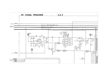
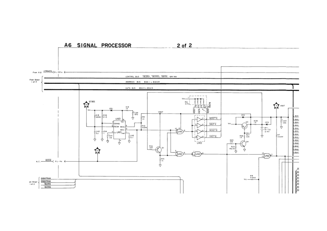
A6 SIGNAL PROCESSOR 2 of 2
From Sheet 1 of 2
From GATE XL-37a
CONTROL BUS TB125A, TB105A, IB1/mA
ADDRESS BUS B461 - B465
DATA BUS B041 - B045
From Sheet 1 of 2
RESIN XL-4a
RESET
VBAT
R5 4.7k
RES1
RESET A
HALT A
U3
U4
U40
U41
U42
U43
U44
U45
U46
U47
U48
U49
U50
U51
U52
U53
U54
U55
U56
U57
U58
U59
detection circuit for each cell • Overcharge detection voltage n (n = 1 to 4) 4.200 V to 4.800 V (in 50 mV steps) Accuracy : ±25 mV (+25°C), Accuracy : ±30 mV (−5°C to +55°C) • Overcharge hysteresis voltage n (n = 1 to 4) −0.520 ±0.210 V, −0.390 ±0.160 V, −0.260 ±0.110 V, −0.130 ±0.06 V, None (2) Delay times
6633B - 020 - FRONT-PANEL BINDING POSTS 6633B - 100 - 87 TO 106 VAC, 47 TO 63 HZ 6633B - 120 - 104 TO 127 VAC, 47 TO 63 HZ 6633B - 1CM - RACK-MOUNT KIT 6633B - 220 - 191 TO 233 VAC, 47 TO 63 HZ 6633B - 230 - 207 TO 253 VAC, 47 TO 63 HZ 6633B - 760 - ISOLATION AND REVERSAL RELAYS
Sammelbestellung Ende Februar 2025 durch Branadic https://www.eevblog.com/forum/metrology/low-thermal-e-m-f-binding-post-tbp3/?all https://www.eevblog.com/forum/metrology/anyone-have-a-source-for-decent-cheap-binding-posts/?all https://www.eevblog.com/forum/metrology/bbs-1ppm-cn-binding-post/?all
Vorschlag: 14W/m, 5m-Rolle für 11€: https://www.reichelt.de/de/de/shop/produkt/led-streifen_warmweiss_5000_mm-235905 Damit wirds ausreichend hell. Zwei in Serie schalten, da nur 12V.
Wulf D. schrieb im Beitrag #7966901: > Vorschlag: 14W/m, 5m-Rolle für 11€: > https://www.reichelt.de/de/de/shop/produkt/led-streifen_warmweiss_5000_mm-235905 > > Damit wirds ausreichend hell. Zwei in Serie schalten, da nur 12V. Blöd halt, dass im Bordnetz
dem 4k7 Pullup und dem 220R Widerstand und es verbleibt bei einem 3V3-I2C-Bus ein Low-Pegel von 130mV. An der Polung dieser 130mV kann man dann sehen, auf welcher Seite die Leitung grade auf Low gezogen wird. > So Serienwiderstaende in Bussen haben gerne mal ein paar Ohm... Das sind dann in den
Max M. schrieb im Beitrag #7961770: > Schon klar, ist aber nicht korrekt. Nach der reinen Lehre muss 16mm² bis > zum "Eigang" des Sicherungselements geführt werden. Unsinn. Bis 3m sind ok.
Michael B. schrieb im Beitrag #7961777: > Max M. schrieb im Beitrag #7961770: >> Schon klar, ist aber nicht korrekt. Nach der reinen Lehre muss 16mm² bis >> zum "Eigang" des Sicherungselements geführt werden. > > Unsinn. > > Bis 3m sind ok
with the formulas below. The theoretical values of L1 and C1 are calculated as follows: 1. Calculate m. m = 50 − 1 = 50 − 1 = 1.508 Rout 15.27 AN5457 - Rev 3 page 22/75 AN5457 Power amplifier network 2. Calculate the value for the matching inductor L1. 1 50m L1 = 2πf × 2 + XC m + 1 1 50 × 1.508 L1 = 2π

 Bild
Bild
 Bild
Bild
 Bild
Bild
 Bild
Bild
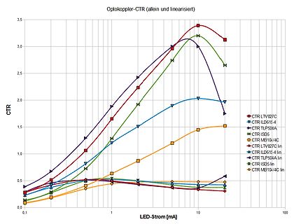
 Bild
Bild
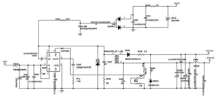
 Bild
Bild

 Bild
Bild
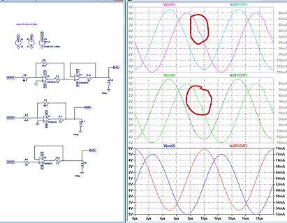
 Bild
Bild