-
Datei
Maxim-Dallas-Liste.txt
docs/7048.pdf us.st.com/stonline/books/pdf/docs/1773.pdf nach cytherm suchen MAX1298 Thermometer with PIC16F84 and LED driver MAX7221 MAX1400 MAX3100 ?? MAX351S 4 Analogschalter für neue DSP-Platine MAX6959 Charlyplexer MAX7221 LED driver for Thermometer with PIC16F84 and MAX1298 DS75 = LM75 kompat DS1775
in „Temperatursteuerung“ · Markt ·
-
Datei
clock_16F88.ASM
!!! bcf EECON1,EEPGD ; !!! necessary for PIC16F88 !!! bsf EECON1, RD ; read character from EEProm banksel EEADR ; !!! necessary for PIC16F88 !!! incf EEADR,f ; inc address for next read movf EEDATA,w ; bsf STATUS,RP1 ; goto Bank2 bcf STATUS,RP0
in „Programm von Pic16F628 für Pic16F88 ändern“ · Mikrocontroller und Digitale Elektronik ·
-
PDF
ATTiny1624.pdf
Pins 14 20 24 Package SOIC SOIC,VQFN VQFN Maximum frequency (MHz) 20 20 20 General purpose I/O 12 18 22 PORT PA[7:0], PB[3:0] PA[7:0], PB[5:0], PA[7:0], PB[7:0], PC[3:0] PC[5:0] External interrupts 12 18 22 Event system channels 6 6 6 CCL LUTs 4 4 4 Real-Time Counter (RTC) 1 1 1 16-bit Timer/Counter
in „Neues Produkt AtTiny1624“ · Mikrocontroller und Digitale Elektronik ·
-
PDF
PIC16F1939.pdf
/96 I/H/E Y PIC16(L)F1946 (4) 8192 256 512 54 17 17 3 4/1 2 2 3 2 4/46/184 I Y PIC16(L)F1947 (4) 16384 256 1024 54 17 17 3 4/1 2 2 3 2 4/46/184 I Y Note 1: Debugging Methods: (I) – Integrated On-Chip; (H) – using Debug
in „MPLAB delay und xtalfreq richtig benutzen“ · Mikrocontroller und Digitale Elektronik ·
-
PDF
40001722A.pdf
I/E Y PIC16(L)F1707 (3) 2048 256 18 8 0 0 2 1 2/1 2 0 0 0 1 0 Y I/E Y PIC16(L)F1708 (1) 4096 512 18 12 1 2 2 1 4/1 2 2 1 1 1 3 Y I/E Y PIC16(L)F1709 (2) 8192 1024 18 12 1 2 2 1 4/1 2 2 1 1 1 3 Y I/E Y Note 1:
in „PIC16(L)F1703 low voltage Programmierung?“ · Mikrocontroller und Digitale Elektronik ·
-
PDF
STM32F429_V1.2.pdf
PIU307LHO PIK101 PIK102 COC2 COR3 PIP201NC GND PIP2020 WP PIU303WP CLK PIU306LCL SW-PB PIC2701 PIC2702 NLOSC0OU 10K GND PIU304GND DIO PIU305LDIO COC2 41 ARM_JTAG PIC2301 PIC2302 22P GND W25Q128 3V3 COJ6 GND COC2 0.1uF PIJ601 1 NLOSC320 PIC2501 PIC25GND GND GND GND PIJ602 2 LED PIR2001PIR2002
in „Hat jemand Erfahrungen mit diesem Board auf Ebay.“ · Mikrocontroller und Digitale Elektronik ·
-
PDF
20002019c.pdf
therefore outside the warranted range. Note: Unless otherwise indicated, T A +25°C with 4.5V V DD 18V. 120 80 10,000 pF 10,000 pF 8,200 pF 100 70 4,700 pF ) 8,200 pF 4,700 pF 60 1,000 pF s 2,500 pF s 6,800 pF ( 80 1,000 pF ( 50 2,500 pF e 6,800 pF e T 60 i 40 e l 30 i 40 a R F 20 20 100 pF 10 100 pF
in „Pulsschweisgerät mit Auto Batt Schaltungs Verbesserung“ · Analoge Elektronik und Schaltungstechnik ·
-
PDF
MCP1403.pdf
therefore outside the warranted range. Note: Unless otherwise indicated, T = +A5°C with 4.5V ≤ V DD ≤ 18V. 100 100 90 6800 pF 90 6800 pF ) 80 4700 pF ) 80 4700 pF n 70 n 70 e 2200 pF e 2200 pF m 60 m 60 T 50 T 50 e l i 40 F 40 R 30 30 20 1800 pF 20 1800 pF 10 10 4 6 8 10 12 14 16 18 4 6 8 10 12 14 16 18
in „MOSFET mit Treiber Verständnisproblem“ · Analoge Elektronik und Schaltungstechnik ·
-
Datei
test.lst
called by: 41 ;; Startup code after reset 42 ;; This function uses a non-reentrant model 43 ;; 44 07F1 _main: 45 07F1 l3: 46 ;incstack = 0 47 ; Regs used in _main: [] 48 ;main.c: 5: while(1); 49 50 07F1 2FF1 goto l3 51 07F2 __end_of_main: 52 007E btemp set 126 ;btemp 53 007E wtemp0 set 126 54 55 psect
in „[C] XC8 verschwendet Speicher“ · Mikrocontroller und Digitale Elektronik ·
-
PDF
Capacitive_Touch_Sensor_Design_Guide_AN2934.pdf
h • Human body model capacitance • Self-capacitance of the human body with respect to earth • 100 pF to 200 pF for an adult depending on physique C g • Capacitance of the coupling between the application DC ground and earth • Depends on application type and power system • Ranging from ~1 pF in a small
in „Wie realisiert man Sensortasten?“ · Analoge Elektronik und Schaltungstechnik ·
-
PDF
ps2.pdf
0x43 0xc3 M 0x32 0xb2 F10 0x44 0xc4 N 0x31 0xb1 F11 0x57 0xd7 O 0x18 0x98 F12 0x58 0xd8 P 0x19 0x99 PRNT SCRN 0xe0, 0x2a, 0xe0, 0xb7 0xe0, 0x37, 0xe0, 0xaa Q 0x10 0x19 SCROLL 0x46 0xc6 R 0x13 0x93 PAUSE 0xe1, 0x1d, 0x45, -none
in „Unbekannter 2-Draht Bus - Event Triggered“ · Mikrocontroller und Digitale Elektronik ·
-
PDF
PIC16F1503.pdf
o e E a r F 1 C i D P T PIC12(L)F1501 (1) 1024 64 6 4 1 1 2/1 4 — — 1 2 1 — — PIC16(L)F1503 (2) 2048 128 12 8 2 1 2/1 4 — 1 1 2 1 — — PIC16(L)F1507 (3) 2048 128 18 12 — — 2/1 4 — — 1 2 1 — — PIC16(L)F1508 (4) 4096 256 18 12 2 1 2/1 4 1 1 1 4 1 Y Y PIC16(L)F1509 (4) 8192 512 18 12 2 1 2/1 4 1 1 1 4 1 Y Y Note 1: One pin is input only. Data Sheet Index: (Unshaded device is described in this document.) 1: Future Product
in „Versorgungsspannung vom PIC mit PIC messen“ · Mikrocontroller und Digitale Elektronik ·
-
Datei
Can.c
*********************************************************** * * This file contains CAN drivers for PIC18Fxx8 devices * ********************************************************************* * FileName: CAN.C * Dependencies: CAN.H, PIC18.H or P18CXXX.H * Processor: PIC18FXX8 * Compiler: MCC18 v2.20 or
in „PIC18F: Probleme mit CAN“ · Mikrocontroller und Digitale Elektronik ·
-
 Bild
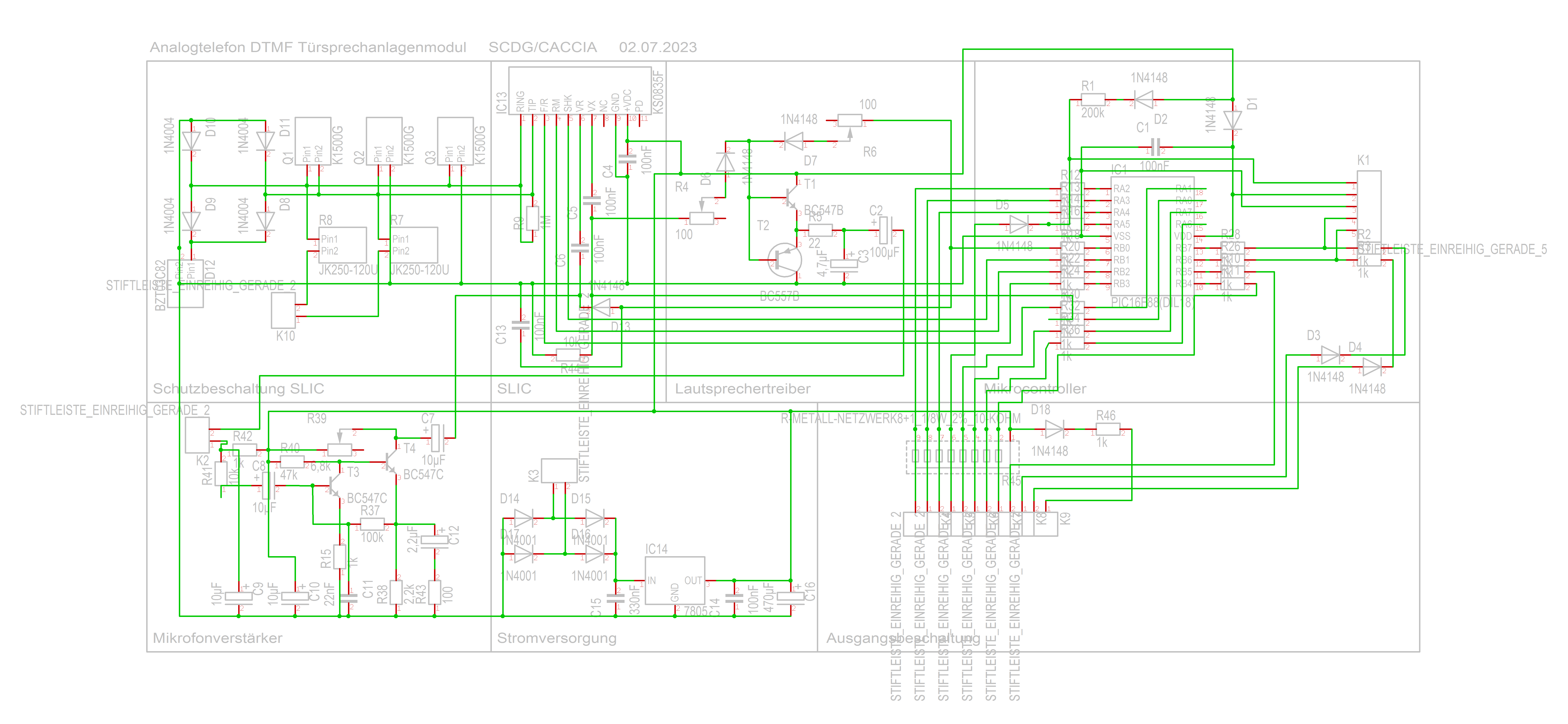
Schaltplan eines Analogtelefon DTMF Sprechanlagenmoduls
Analogtelefon DTMF Sprechanlagenmodul SCDG/CACCIA 02.07.2023 1N4148 100 200k R1 1N4148 D1 K1 100uF C1 1N4148 D7 R6 T1 BC547B C2 100uF R2 R3 R4 R5 R6 R7 R8 R9 R10 R11 R12 R13 R14 R15 R16 R17 R18 R19 R20 R21 R22 R23 R24 R25 R26 R27 R28 R29 R30 R31 R32 R33 R34 R35 R36 R37 R38 R39 R40 R41 R42 R43 R44
in „DTMF Türsprechmodul mit PIC16F8x - Prüfung und Programmierung“ · Mikrocontroller und Digitale Elektronik · · Schaltpläne
-
PDF
PICkit_3_Programmer_Application_User_s_Guide_50002158a.pdf
the device during programming, a Bulk Erase method is used. All Base- line, Mid-Range, and many dsPIC30F and PIC18F devices require a minimum V DD for the Bulk Erase. Some of these devices support a low-voltage row erase method that can be used at lower voltages. However, this method takes longer to
in „PICkit3 und Windows 11“ · Mikrocontroller und Digitale Elektronik ·
-
PDF
MPLINK_TUTORIAL.pdf
in all banks SHAREBANK NAME=sfrnobnk START=0x200 END=0x20F PROTECTED //INDF0 thru BSR - available in all banks SHAREBANK NAME=sfrnobnk START=0x300 END=0x30F PROTECTED //INDF0 thru BSR - available in all banks SHAREBANK NAME=sfrprod START=0x18 END=0x19 PROTECTED
in „Anfängerfrage zu Assembler“ · Mikrocontroller und Digitale Elektronik ·
-
PDF
70599B.pdf
Omniscient Code suits, or expenses resulting from such use. No licenses are Generation, PICC, PICC-18, PICDEM, PICDEM.net, PICkit, conveyed, implicitly or otherwise, under any Microchip PICtail, PIC2 logo, REAL ICE, rfLAB, Select Mode, Total intellectual property rights. Endurance, TSHARC, UniWinDriver
in „AVR32UC3B mit Funkmodul MRF24J40MB“ · Mikrocontroller und Digitale Elektronik ·
-
 Bild
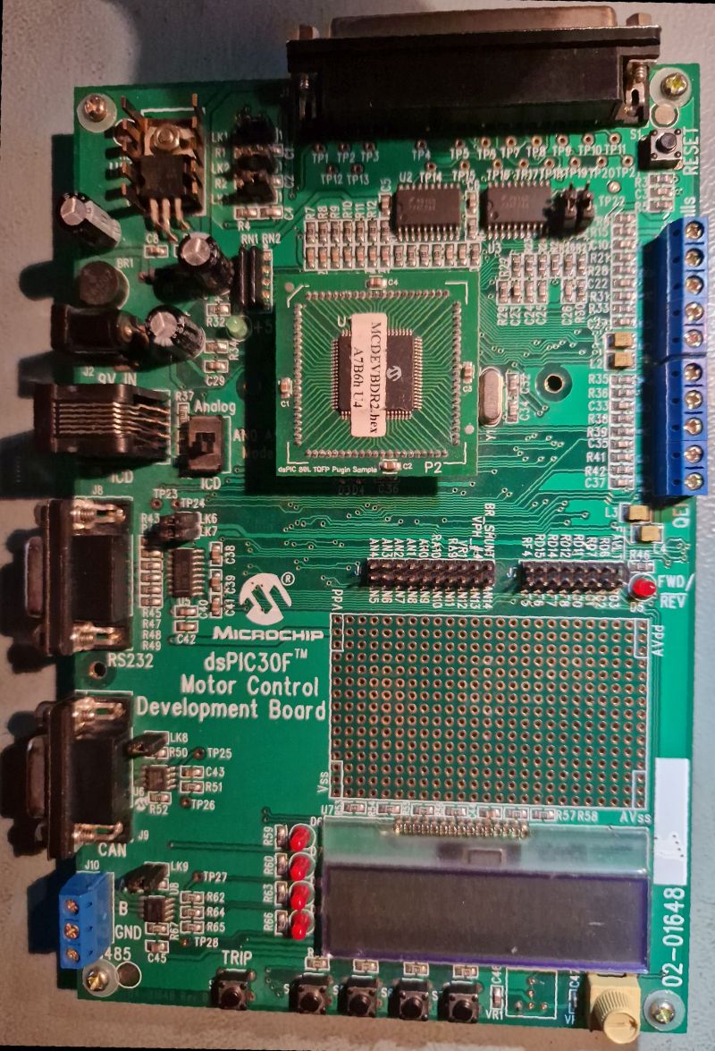
dsPIC30F Motor Control Development Board
TP8 TP9 TP10 TP11 TP12 TP13 TP14 TP15 R1 R2 R3 R4 R5 R6 R7 R8 R9 R10 R11 R12 R13 R14 R15 R16 R17 R18 R19 R20 R21 R22 R23 R24 R25 R26 R27 R28 R29 R30 R31 R32 R33 R34 R35 R36 R37 R38 R39 R40 R41 R42 R43 R44 R45 R46 R47 R48 R49 R50 R51 R52 R53 R54 R55 R56 R57 R58 R59 R60 R61 R62 R63 R64 R65 R66 R67 R68
in „[V] ältere Demoboards PIC, NEC und Motor“ · Markt · · Platinenfotos
-
PDF
Grundig-DVDP-7000-Service-Manual.pdf
33p 33p 33p 33p 33p HU- 13 9 20 HW+ 14 HW- H1+ FR HW- 15 HV+ 10 19 C812 HV+ 16 H1- NC HV- 17 VH 11 18 100n EMI Solution EMI Solution H+ 18 H2+ SB H- 12 17 H2- CNF FPC18_5MM 13 H3+ NC 16 to Disc & Sledge Motor 14 H3- VH 15 R816 100 VH F F M5V 9 0 C811 R815 R814 100 2 3 100n 100K D V D P 0 0 0 G R Hauptplatte
in „800x480-Farbdisplay mit uC verwenden“ · Mikrocontroller und Digitale Elektronik ·
-
Datei
tft_data.c
0x8C, 0x8E, 0xD1, 0x31, 0x3A, 0x46, 0xC7, 0xE8, 0x18, 0x1D, 0xA3, 0x63, 0x74, 0x8C, 0x8E, 0xD1, 0x31, 0x3A, 0x46, 0xC7, 0xE8, 0x18, 0x1D, 0xA3, 0xBD, 0x11, 0xF3, 0x47, 0x7F, 0x80, 0x8E, 0xF1, 0x1F, 0x3C, 0x24, 0xB0, 0x98, 0x0E, 0x0C,
-
PDF
io-controller-hub-9-datasheet.pdf
Capability Register (Intel High Definition Audio Controller—D27:F0)..................................... 719 18.1.45VCiCTL—VCi Resource Control Register (Intel High Definition Audio Controller—D27:F0)..................................... 719 18.1.46VCiSTS—VCi Resource
in „FLASH Memory Chip im Lenovo X200 von 8 MB auf 16 MB vergroessern“ · PC Hard- und Software ·
-
Datei
TFT3.2.c
int x2,unsigned int y2) { write_com_data(0x44,(x2<<8)+x1); write_com_data(0x45,y1); write_com_data(0x46,y2); write_com_data(0x4E,x1); write_com_data(0x4F,y1); write_com(0x00,0x22); } //************************************************************************* // set window for SainSmart 3.2 LCD //******
-
PDF
88E1111_DS.pdf
Interrupt Enable Enable r 0 c F 18.8 4FaNse Carrier Interrupt Enable ct 13 n O 18.6a- MDI Crossover Changed Interrupt Enable i L 18f5 L Downshift Interrupt Enable o A# e E 18.3E Reservedetect Interrupt EnableicND e A 318.2 DTE Power
-
Datei
irsnd.c
* SIEMENS_OR_RUWIDO_FRAME_REPEAT_PAUSE_TIME + 0.5) // use uint16_t! #ifdef PIC_C18 // PIC C18 # define IRSND_FREQ_TYPE uint8_t # define IRSND_FREQ_30_KHZ (IRSND_FREQ_TYPE) ((F_CPU / 30000 / 2 / Pre_Scaler / PIC_Scaler) - 1) # define IRSND_FREQ_32_KHZ (IRSND_FREQ_TYPE) ((F_CPU
in „IRMP - Infrared Multi Protocol Decoder“ · Projekte & Code ·
-
PDF
my_float_projejt.pdf
0x33,0x33,0x7E,0x00,0x1E,0x33,0x60,0x60,0x60,0x33,0x1E,0x00,0x7C,0x36,0x33,0x33,0x33,0x36,0x7C,0x00,0x7F,0x31,0x34,0x3C,0x34,0x31,0x7F,0x00,0x7F,0x31,0x34,0x3C,0x34,0x30,0x78,0x00,0x1E,0x33,0x60,0x60,0x67,0x33,0x1F,0x00,0x66,0x66,0x66,0x 7E,0x66,0x66,0x66,0x00,0x3C,0x18,0x18,0x18,0x18,0x18,0x3C,0x00,0x0F
in „Microchip springt auf den Arduino Zug auf“ · Mikrocontroller und Digitale Elektronik ·
-
PDF
DS_BT81X.pdf
31 41 52 118 v 8 6 7 8 10 13 16 7 9 11 12 16 21 27 36 46 119 w 8 8 10 12 14 18 23 11 13 16 18 23 32 41 54 70 120 x 8 6 7 8 10 12 16 7 9 11 12 16 21 27 36 46 121 y 8 5 7 8 10 13 16 7 9 11 12 16 21 27 36 46 122 z 8 5 7 8 9 12 16 8 9 11 12 15 22 27 36 46 123
in „STM32F407 DISCOVERY mit EVE3 50GTPC von MatrixOrbital“ · Mikrocontroller und Digitale Elektronik ·
-
Datei
standard.bjt.txt
Itf=14.46 Xtf=75.99 Vtf=10 Vceo=40 Icrating=1 mfg=Philips) .model BSV16-6 PNP(Is=70.49f Xti=3 Eg=1.11 Vaf=100 Bf=78.81 Ise=795.9f Ne=1.5 Ikf=.9977 Nk=.6579 Xtb=1.5 Br=18.45 Isc=715.1f Nc=1.23 Ikr=1.222 Rc=.8335
in „Hilfe bei LTSpice nötig!“ · Analoge Elektronik und Schaltungstechnik ·
-
PDF
MCP2021.pdf
conditions: 1 nF; 1 k | 6.8 nF; 660 | 10 nF; 500 TH REC(MAX) = 0.284 x BB, TH DOM(MAX ) = 0.422 x BB, VBB =7.6V - 18V; BIT= 50 µs. D2 = tUS _REC(MAX ) / 2 BIT) Duty Cycle 3 @10.4 kbit/sec .417 — — %t BIT CBUS ;RBUS conditions: 1 nF; 1 k | 6.8 nF; 660 | 10 nF; 500 TH REC(MAX) = 0.778 x BB, TH DOM(MAX ) = 0.616 x BB, VBB =7.0V - 18V; BIT= 96 µs. D3 = BUS _REC(MIN) / 2 xBI) Duty Cycle 4 @10.4 kbit/sec — — .590 %t BIT CBUS ;RBUS
in „MCP2021 -> Welcher ESD Level wird erreicht“ · Mikrocontroller und Digitale Elektronik ·
-
PDF
MCP320412-bitA-DConverterDatasheet.pdf
1 2 3 4 5 0 1 2 3 4 5 V REF(V) V REF (V) FIGURE 2-15: Gain Error vs. V REF . FIGURE 2-18: Offset Error vs. V REF . DS21298C-page 8 2002 Microchip Technology Inc. MCP3204/3208 Note: Unless otherwise indicated, V DD = V REF = 5V, V SS = 0V, f SAMPLE = 100 ksps, f CLK = 20* f SAMPLE ,T A
-
PDF
STM32H7-Disco_full.PDF
1.5mm CJ9 PJ85 1 1 1 PR0 PR0 PU3Vin_3 LX_14 PI94 1 10 uH 1 1 1 1 120@100MHz TP2 IN PJ0 PJ84 N074 27 PIC40 P4C41 P8C38 0R P0D5 PI1C39 PICO42 PIC45 PCC47 PJ83 +7.4V PI4.7uF P44.7uF P81.0uF PU4Vcc C43 P0SSL34 PI2100nFPI4.7uF PI4.7uF PC4.7uF IN PJ0 PJ82 P0 2 2 2 P0 PU5En BootPI95PI31PI32 2 2 2 2 2 P4 ScrewClip 2x PJ81 CJ CC4 100nF O4 STL_100mil_1x5 +J10 44 1P91Pgood VbiasPI91 C48 HA 1X18650 201.0uF PU7SyncH 24470pF - 1P91FSW Comp PI98 1 1 1 GND 1P91Ilim GND PI1OC P P4 20 PU6SS FB PI99 C49 R48 C46 R46 R47 +3.7V GND 1 1 1 1P91Gnd
in „STM32H7-Disco erster Test“ · Mikrocontroller und Digitale Elektronik ·
-
PDF
Datenblatt_PIC12F1822.pdf
See APFCON register (Register 12-1). 2010 Microchip Technology Inc. Preliminary DS41413B-page 17 PIC12F/LF1822/PIC16F/LF1823 NOTES: DS41413B-page 18 Preliminary 2010 Microchip Technology Inc. PIC12F/LF1822/PIC16F/LF1823 2.0 ENHANCED MID-RANGE CPU This family of devices contain an enhanced mid-range
in „PIC12F1822-PWM Mode“ · Mikrocontroller und Digitale Elektronik ·
-
PDF
Datenblatt_PIC12F1822.pdf
See APFCON register (Register 12-1). 2010 Microchip Technology Inc. Preliminary DS41413B-page 17 PIC12F/LF1822/PIC16F/LF1823 NOTES: DS41413B-page 18 Preliminary 2010 Microchip Technology Inc. PIC12F/LF1822/PIC16F/LF1823 2.0 ENHANCED MID-RANGE CPU This family of devices contain an enhanced mid-range
in „Interrupt-PIC12F1822“ · Mikrocontroller und Digitale Elektronik ·
-
PDF
12F1822_1823.pdf
See APFCON register (Register 12-1). 2010 Microchip Technology Inc. Preliminary DS41413B-page 17 PIC12F/LF1822/PIC16F/LF1823 NOTES: DS41413B-page 18 Preliminary 2010 Microchip Technology Inc. PIC12F/LF1822/PIC16F/LF1823 2.0 ENHANCED MID-RANGE CPU This family of devices contain an enhanced mid-range
in „Auflösung PWM-Mode“ · Mikrocontroller und Digitale Elektronik ·
-
PDF
12F1822_1823.pdf
See APFCON register (Register 12-1). 2010 Microchip Technology Inc. Preliminary DS41413B-page 17 PIC12F/LF1822/PIC16F/LF1823 NOTES: DS41413B-page 18 Preliminary 2010 Microchip Technology Inc. PIC12F/LF1822/PIC16F/LF1823 2.0 ENHANCED MID-RANGE CPU This family of devices contain an enhanced mid-range
in „8Bits und 2Bits in eine Integer-Variable“ · Mikrocontroller und Digitale Elektronik ·
-
PDF
12F1822_1823.pdf
See APFCON register (Register 12-1). 2010 Microchip Technology Inc. Preliminary DS41413B-page 17 PIC12F/LF1822/PIC16F/LF1823 NOTES: DS41413B-page 18 Preliminary 2010 Microchip Technology Inc. PIC12F/LF1822/PIC16F/LF1823 2.0 ENHANCED MID-RANGE CPU This family of devices contain an enhanced mid-range
in „Timer2 auf 10bit einstellen“ · Mikrocontroller und Digitale Elektronik ·
-
PDF
PIC12FLF1822PIC16FLF1823.pdf
See APFCON register (Register 12-1). 2010 Microchip Technology Inc. Preliminary DS41413B-page 17 PIC12F/LF1822/PIC16F/LF1823 NOTES: DS41413B-page 18 Preliminary 2010 Microchip Technology Inc. PIC12F/LF1822/PIC16F/LF1823 2.0 ENHANCED MID-RANGE CPU This family of devices contain an enhanced mid-range
in „PIC16lf1823 General purpose I/Os mit Schmitt Trigger ?“ · Mikrocontroller und Digitale Elektronik ·
-
PDF
Bidirektionale_RS232_Funkbr_cke_mit_RFM12_2.pdf
benedikt) (Moderator) Datum: 16.07.2007 15:07 Wenn ich richtig gerechnet habe, schafft der MAR4 etwa 18mW, der MAR1 dagegen nur 1,8mW. Es wäre also kein Verstärker, sondern ein Abschwächer. Leider sagen mir die meisten Daten nichts. Könnte mich mal jemand aufklären, was "N.F. (dB)" und "VSWR (:1), Out"
in „bidirektionale RS232 Funkbrücke mit RFM12“ · Projekte & Code ·
-
Datei
GLCD.h
#define R9 0x09 #define R10 0x0A #define R12 0x0C #define R13 0x0D #define R14 0x0E #define R15 0x0F #define R16 0x10 #define R17 0x11 #define R18 0x12 #define R19 0x13 #define R20 0x14 #define R21 0x15 #define R22 0x16 #define R23 0x17 #define R24 0x18 #define R25 0x19 #define R26 0x1A #define R27
in „STM32 24Bit Bmp nach 565RGB Format“ · Mikrocontroller und Digitale Elektronik ·
-
Datei
All.txt
1 U$1 SC08-11 SC08-11 SC08 1 U$1 S1D13706 S1D13706 SQFP-S-14X14-100 LCD Graphics Controller 1 U$1 PIC18F4520-E/P PIC18F4520-E/P DIL40 PIC18*4520 Microchip FLASH Microcontroller with A/D 1 U$1 PIC16F628AI/P PIC16F628AI/P DIL18 MICROCONTROLLER 1 U$1 NC NC NC No connect symbol 1 U$1 MOC3020M MOC3020M DIL06
in „[KiCad] Bibliotheksaufbau - Konzeptideen gesucht“ · Platinen ·
-
PDF
21709c_EEPROM.pdf
8.26 Molded Package Width E1 .240 .250 .260 6.10 6.35 6.60 Overall Length D .360 .373 .385 9.14 9.46 9.78 Tip to Seating Plane L .125 .130 .135 3.18 3.30 3.43 Lead Thickness c .008 .012 .015 0.20 0.29 0.38 Upper Lead Width B1 .045 .058 .070 1.14 1.46 1.78 Lower Lead Width B .014 .018 .022 0.36 0.46
in „EEPROM mit Infineon XC2200 ueber IIC benutzten“ · Mikrocontroller und Digitale Elektronik ·
-
PDF
21709c.pdf
8.26 Molded Package Width E1 .240 .250 .260 6.10 6.35 6.60 Overall Length D .360 .373 .385 9.14 9.46 9.78 Tip to Seating Plane L .125 .130 .135 3.18 3.30 3.43 Lead Thickness c .008 .012 .015 0.20 0.29 0.38 Upper Lead Width B1 .045 .058 .070 1.14 1.46 1.78 Lower Lead Width B .014 .018 .022 0.36 0.46
in „24LC02B mit (scheinbar) seltsamer Adressierung“ · Mikrocontroller und Digitale Elektronik ·
-
PDF
Class_1_Bluetooth_Module_with_EDR_Support_DS500022-2257897.pdf
Product Development, Quicker Time to Market • Compatible with Microchip Microcontroller Fami- lies (PIC16F, PIC18F, PIC24F/H, dsPIC33 and PIC32) • Up to 100 meter range 2021 Microchip Technology Inc. DS50002280B-page 1 RN41/RN41N RN41/RN41 MODULE VARIANTS (1) Model Antenna Firmware Description RN41
in „[V] Microchip Bluetooth Module RN41-I/RM und RN42-I/RM“ · Markt ·
-
PDF
___MPASM_USER_S_GUIDE_with_MPLINK_and_MPLIB.pdf
f,d Rotate right f register f C 7......0 08f SUBWF f,d Subtract W from f f - W → d 38f SWAPF f,d Swap halves f f(0:3) ↔ f(4:7) → d 18f XORWF f,d Exclusive OR W and f W .XOR. f → d Table E.7 PIC16C5X Bit
in „Anfängerfrage zu Assembler“ · Mikrocontroller und Digitale Elektronik ·
-
 Bild
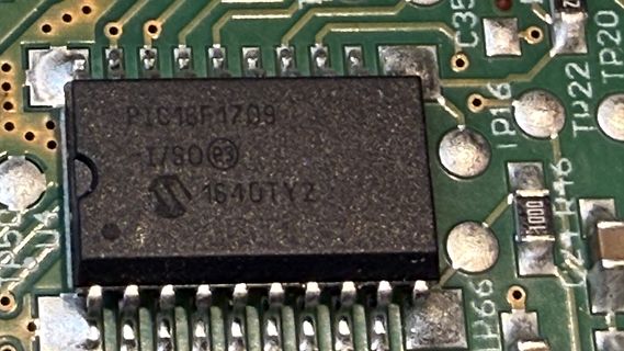
Nahaufnahme eines PIC18F1709 Mikrocontrollers auf einer Leiterplatte
PIC18F1709 I/SO e3 1640TY2 C35 TP20 TP16 R46 1000 TP66
in „Bosch MUM6 Viper defekt“ · Haus & Smart Home · · Platinenfotos
-
Datei
GLCD.h
#define R9 0x09 #define R10 0x0A #define R12 0x0C #define R13 0x0D #define R14 0x0E #define R15 0x0F #define R16 0x10 #define R17 0x11 #define R18 0x12 #define R19 0x13 #define R20 0x14 #define R21 0x15 #define R22 0x16 #define R23 0x17 #define R24 0x18 #define R25 0x19 #define R26 0x1A #define R27
in „STM32 24Bit Bmp nach 565RGB Format“ · Mikrocontroller und Digitale Elektronik ·
-
Datei
NEW_MAP.txt
// FIRMWARE REPLACEMENT FOR CHATPAD's pic16f883 // see attached documents to learn more // release 0.3.1 from jean : giancarlotodone at yahoo dot it // for the Open Keyboard Project // thanks alot to Gidi (who owns an half of my chatpad, call
in „Chatpad PIC16F883“ · Mikrocontroller und Digitale Elektronik ·
-
PDF
Class_2_Bluetooth_Module_with_EDR_Support_DS500023-2256355.pdf
SMT pads for easy and reliable PCB • Compatible with Microchip Microcontroller Families mounting (PIC16F, PIC18F, PIC24F/H, dsPIC33 and PIC32) • Class 2 power amplifier with on-board PCB trace antenna (RN42) or external antenna (RN42N) • Up to 10 meter range • Compliance (RN42) Applications - Modular
in „[V] Microchip Bluetooth Module RN41-I/RM und RN42-I/RM“ · Markt ·
-
Datei
Klingel.asm
0x10 retlw 0x0D retlw 0x00 retlw 0x0F retlw 0x00 retlw 0x0D retlw 0x00 retlw 0xDB retlw 0x1F retlw 0x00 retlw 0x1C retlw 0x30 retlw 0x1F retlw 0x00 retlw 0x1C retlw 0x30 retlw 0x1A retlw 0x00 retlw 0x18 retlw 0x00 retlw 0x1A retlw 0x00 retlw
-
PDF
90000897.pdf
ME 9210 9210 r M t E 1 VETH+ n 2 s , 2 VETH- W M 3-6 Positions Removed E 2 1 7 RXD A3 GPIO DATA IN PIC_0_ 0 [3] GEN_IO[3] a d 2 8 TXD A7 GPIO DATA OUT Timer Out 7 a Timer In 8 e [7] e 3 9 RTS A5 GPIO 3 CLK Timer Out 6 e n [5] e M 4 10 DTR A6 GPIO PIC_CAN_ Timer In 7 n [6] TXD a l 5 11 CTS A1 GPIO 0 PIC_0_ [1] GEN_IO[1] 6 12 DSR A2 GPIO 1 PIC_0_ PIC_CAN_ [2] GEN_IO[2] RXD 7 13 DCD A0 GPIO EN PIC_0_ [0] GEN_IO[0] 8 14 /RST 9 15 3.3V o u e n u 5 t D P g o C PIN UART GPIO Ext Ext I2C SPI FIM CAN BUS Timer Other r n [All] GPIO [ME IRQ IRQ [ME
in „[V] WEITERE gebrauchte DIGI-Connect-ME LAN-Seriell Module (10€/St.)“ · Markt ·