-
Datei
log.txt
button_init... timer2_init... wpsbutton_init... Version: 2.9.4 Hardware: STM32F103 Display: WC12h LEDs: WS2812 GRB rtc is online eeprom is online ws2812: external pullup detected eeprom is online current eeprom version: 0x00020900 reading ir codes from eeprom DFPLAYER LOGGER ESP8266 LOGGER read rtc: Fr 2019
-
Datei
main12.asm
LED3 Magenta movwf rgb_byte+6 movlw 0xFF movwf rgb_byte+7 movlw 0xFF movwf rgb_byte+8 call transmit_WS2812 goto $ ;*******************************************************************************; transmit_WS2812 movlw high(rgb_byte) movwf FSR0H movlw low(rgb_byte) movwf FSR0L BANKSEL SSP1BUF movf INDF0
in „[ASM & C] PIC12/PIC18/PIC24 WS2812 SPI Library“ · Projekte & Code ·
-
Datei
main18.asm
rgb_byte+6,ACCESS movlw 0xFF movwf rgb_byte+7,ACCESS movlw 0xFF movwf rgb_byte+8,ACCESS call transmit_WS2812 goto $ transmit_WS2812 movlw high(rgb_byte) movwf FSR0H movlw low(rgb_byte) movwf FSR0L movf INDF0,w movwf tx_buf,ACCESS txloop_1 movlw .7 ; Transmit 7 bits movwf tx_cnt,ACCESS txloop_0 movlw b'11111100
in „[ASM & C] PIC12/PIC18/PIC24 WS2812 SPI Library“ · Projekte & Code ·
-
PDF
PitschLight_Doku_V1.2.pdf
von LEDs zu bestimmen, sollte man die Glasscheibe des TV ausmessen und entsprechend lange Stücke von WS2812-Streifen abschneiden. Evtl. müssen die etwas kürzer sein, da die Montagemöglichkeiten auf der Rückseite dies erfordern. Kleinere Abweichungen zwischen Abmessungen des Schirms und Länge der Streifen
in „Ambilight mit STM32F4discovery und TVP5150AM1“ · Mikrocontroller und Digitale Elektronik ·
-
PDF
WC_MiniDev_Shield_v6.pdf
1 Data RESET GPIO14 GPIO0 A4 IRF9310 B1 1 IC2A B9 2 PON GPIO12 GPIO2 C4 3 A9 GPIO13 GPIO15 GPIO15 WS2812 4 GDN VCC GND R10 100nF LM358N VCC B0 Q1 4 6 +3V3 2 k 82 BS170 R8 7 DCF77 1 0 0 a R 1 R 1 4 n LED1 680 5 4 12 T t DCF IC2B T DD B O R8, LED1 und IC2 nur erforderlich, GND B 2 wenn DCF verwendet wird
-
Datei
Treppenbeleuchtung-WS2812B.ino
#include <Adafruit_NeoPixel.h> #include <Wire.h> #ifdef __AVR__ #include <avr/power.h> #endif /*******************************Variablendeklaration***********************************/ int Melder_unten = 22; // Input Bewegungsmelder unten int Melder_oben = 23; // Input Bewegungsmelder oben int Nanopixel = 6; // Output für NanoPixel LEDs int VZ = 15; // Verzögung Ansteuerung der Stufen int Dauer = 30000; // Leuchtdauer wenn alle Stufen angesteuert sind int Sperrzeit = 60000; // Sperrzeit bevor die Scheife beendet wird und die anderen Laufen kann bool BWU,BWO; float PIXEL; #define NUMPIXELS 394 // Anzahl
in „Dynamischer Variablenname in Scheife hochzählen“ · Mikrocontroller und Digitale Elektronik ·
-
Datei
stm32f1xx_hal_msp.c
END TIM1_MspPostInit 0 */ /**TIM1 GPIO Configuration PA9 ------> TIM1_CH2 */ GPIO_InitStruct.Pin = WS2812_Pin; GPIO_InitStruct.Mode = GPIO_MODE_AF_PP; GPIO_InitStruct.Speed = GPIO_SPEED_FREQ_LOW; HAL_GPIO_Init(WS2812_GPIO_Port, &GPIO_InitStruct); /* USER CODE BEGIN TIM1_MspPostInit 1 */ /* USER CODE
in „STM32F103 Hardfault“ · Mikrocontroller und Digitale Elektronik ·
-
Datei
Weihnachtsledas.ino
strip.begin(); strip.show(); } void loop(){ if (digitalRead(2) == HIGH){ loop();{ if (go==1) { cli(); ws2812_sendarray(display_buffer, NUMBER_OF_PIXELS * 3); sei(); go=0; } } ISR(USART_RX_vect) { unsigned char b; b=UDR0; if (b == 1) {pos=0; ptr=display_buffer; return;} if (pos == (NUMBER_OF_PIXELS*3)) {} else {*ptr=b; ptr++; pos++;} if (pos == ((NUMBER_OF_PIXELS*3)-1)) {go=1;} } void ws2812_sendarray(uint8_t *data,uint16_t datlen) { uint8_t curbyte,ctr,masklo; uint8_t maskhi = _BV(DATA_PIN); masklo =~ maskhi & DATA_PORT; maskhi |= DATA_PORT; while (datlen--) { curbyte = *data++; asm
in „Auswahl zweier Arduino Sketches“ · Mikrocontroller und Digitale Elektronik ·
-
PDF
Schematic_ESP32-MES-WiFi_2026-03-31.pdf
Company: Your Company Sheet: 1/1 Date: 2019-05-15 Drawn By: g3gg0.de 1 2 3 4 5 1 2 3 4 5 T VCC ESP32 _ WS2812 P 2 1 U4 M L L ESP32-WROOM/WROVER T R R I E O D D R 1 2 A R7 N N N 2 1 A 1k O O O S 2 23 16 L L L W S 24O15 I153 W 25O2 G14 VCC5 IO0 26O0 I132 LED5 WDT_WDI 27O4 I124 STATUS 28C I117 DI GND 29C I106 30O5 I925 WS2812 VCC5 VCC 31O18 I833 APP+ 32O19 I732 APP- VDD DO 33C I635 34O21 I534 ADC RXD0 35XD0 S4NSOR_VN VN TXD0 36XD0 S3NSOR_VP VP 37O22 E2 RESET 38O23 V1D33 39ND GND GND B GND GND1 VCC B DISPLAY Header 1 2
in „LON Bus Windhager mitlesen/steuern“ · Softwareentwicklung ·
-
Datei
Forum1.ino
#include <sainsmartkeypad.h> /* Digital Light Wand + SD + LCD + Arduino MEGA - V MRR-3.0 (WS2812 RGB LED Light Strip) by Michael Ross 2014 Based on original code by myself in 2010 then enhanced by Is0-Mick in 2012 The Digital Light Wand is for use in specialized Light Painting Photography Applications. This code is totally rewritten using code that IsO-Mick created made to specifically support the WS2812 RGB LED strips running with an SD Card, an LCD Display, and the Arduino Mega 2560 Microprocessor board. The functionality that is included in this code is as follows: Menu System 1 - File select
in „arduino display geht aus“ · Mikrocontroller und Digitale Elektronik ·
-
Datei
WS2812x300-Christmas.ino
#include <Adafruit_NeoPixel.h> #ifdef __AVR__ #include <avr/power.h> #endif // Which pin on the Arduino is connected to the NeoPixels? const uint8_t PIN = 6; // make sure to set this to the correct PixelPin, ignored for Esp8266 // How many NeoPixels are attached to the Arduino? const uint16_t NUMPIXELS = 300; // When we setup the NeoPixel library, we tell it how many pixels, and which pin to use to send signals. // Note that for older NeoPixel strips you might need to change the third parameter--see the strandtest // example for more information on possible values. Adafruit_NeoPixel pixels = Adafruit_NeoPixel
in „Zeigt her eure elektronischen Weihnachtsbasteleien!“ · Projekte & Code ·
-
PDF
Schematic_bruce-2_2024-12-19.pdf
1 2 3 4 5 6 7 8 9 10 11 12 13 A A checked LED GND LED3 C13 LED7 C14 WS2812-SMD2020 100nf WS2812-SMD2020 100nf VOUT 4 +5V DOUT 1 4 +5V DOUT 1 3 DIN GND 2 3 DIN GND 2 LED GND GND BATTERY CHARGER checked B B VIN C28 C19 C24 GND 22uf 100nf 100nf GND U11 N 10uf BQ25896RTWT G
in „Möglicher Fehler mit AO3400 und Bauteilen U4 Bruce github“ · Mikrocontroller und Digitale Elektronik ·
-
PDF
Schematic_bruce-2_2024-12-19.pdf
1 2 3 4 5 6 7 8 9 10 11 12 13 A A checked LED GND LED3 C13 LED7 C14 WS2812-SMD2020 100nf WS2812-SMD2020 100nf VOUT 4 +5V DOUT 1 4 +5V DOUT 1 3 DIN GND 2 3 DIN GND 2 LED GND GND BATTERY CHARGER checked B B VIN C28 C19 C24 GND 22uf 100nf 100nf GND U11 N 10uf BQ25896RTWT G
in „Möglicher Fehler mit AO3400 und Bauteilen U4 Bruce github“ · Mikrocontroller und Digitale Elektronik ·
-
PDF
TMS320F2812_Datasheet.pdf
April 2001 − Revised July 2007 SPRS174O 5 Figures List of Figures Figure Page Figure 2−1. TMS320F2812 and TMS320C2812 179-Ball GHH MicroStar BGA (Bottom View) . . . . . . . . . . . . . 14 Figure 2−2. TMS320F2812 and TMS320C2812 176-Pin PGF LQFP (Top View) . . . . . . . . . . . . . . . . . . . . . .
in „Wieder eine Elektronik-Anfängerfrage“ · Mikrocontroller und Digitale Elektronik ·
-
Datei
Sperlings_VU_UNO.ino
AMBILIGHTBRIGHTNESS = 75; # define COLOR_ORDER GRB // Colour order of LED strip [GRB] # define LED_TYPE WS2812B // LED string type [WS2812B] # define DC_OFFSET 0 // DC offset in aux signal [0] # define NOISE 0 // Noise/hum/interference in aux signal [0] # define SAMPLES 64 // Length of buffer for dynamic
in „Arduino Sketch mittels Kippschalter anders "loopen" lassen“ · Projekte & Code ·
-
Datei
strandtest.ino
pixel type flags, add together as needed: // NEO_KHZ800 800 KHz bitstream (most NeoPixel products w/WS2812 LEDs) // NEO_KHZ400 400 KHz (classic 'v1' (not v2) FLORA pixels, WS2811 drivers) // NEO_GRB Pixels are wired for GRB bitstream (most NeoPixel products) // NEO_RGB Pixels are wired for RGB bitstream
in „Auswahl zweier Arduino Sketches“ · Mikrocontroller und Digitale Elektronik ·
-
Bild
-
Bild
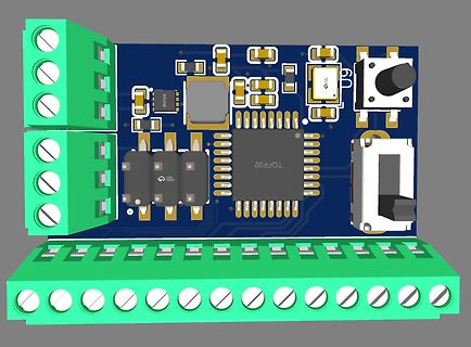
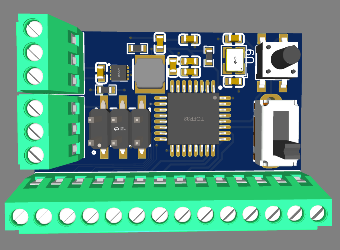
3D-Modell einer Leiterplatte mit Mikrocontroller und Klemmen
WS2812, TQFP32
in „LED Zuleitungen reduzieren.“ · Mikrocontroller und Digitale Elektronik · · Layouts
-
Bild
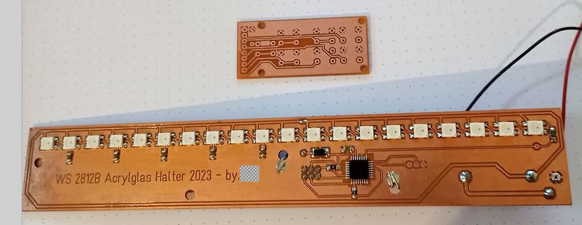
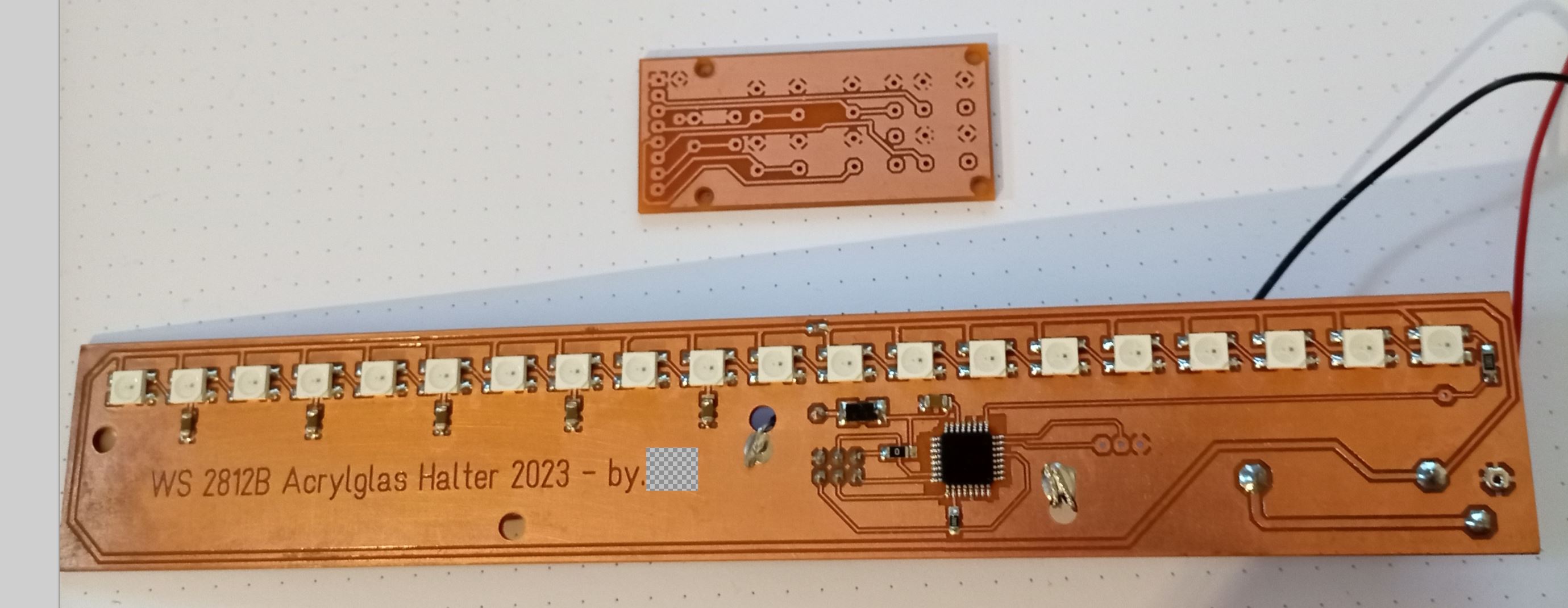
Zwei geätzte Leiterplatten mit LEDs und IC
WS 2812B Acrylglas Halter 2023 - by
in „Hilfestellung bei der Auswahl des richtigen PCB-Prototypen-Erstellungswerzeugs“ · Platinen · · Platinenfotos
-
Bild
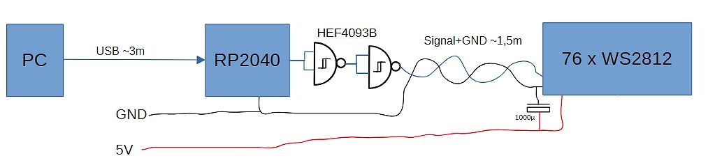
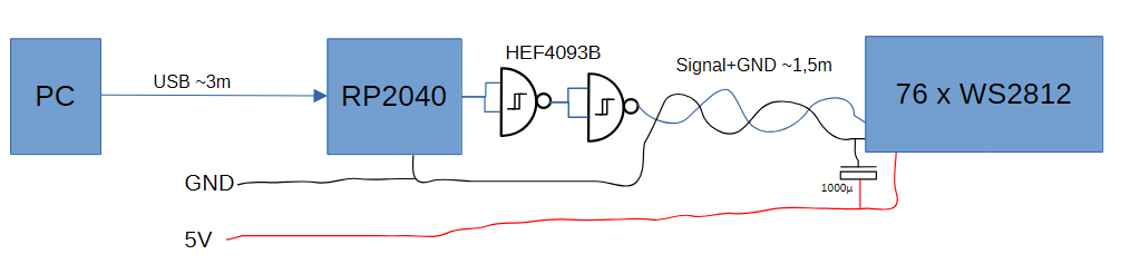
Blockschaltbild einer LED-Steuerung mit RP2040 und Pegelwandler
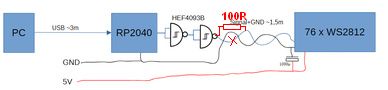
PC USB ~3m RP2040 HEF4093B Signal+GND ~1,5m 76 x WS2812 GND 1000µ 5V
in „PC-USB --> RP2040 --> WS2812: Kabellänge“ · Analoge Elektronik und Schaltungstechnik · · Diagramme
-
Bild
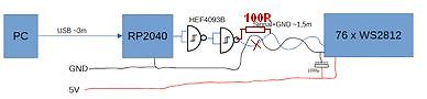
Blockschaltbild einer LED-Ansteuerung mit RP2040 und HEF4093B
PC USB ~3m RP2040 HEF4093B 100R Signal+GND ~1.5m 76 x WS2812 GND 100nF 5V
in „PC-USB --> RP2040 --> WS2812: Kabellänge“ · Analoge Elektronik und Schaltungstechnik · · Diagramme
-
Bild
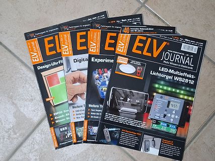
Mehrere Ausgaben des ELV Journals
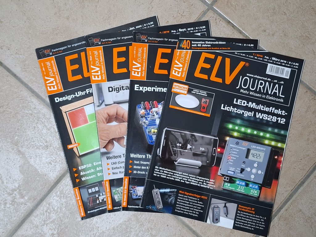
2020, Aug./Sept. 2019, Feb./März 2019, Design-Uhr, Digitale Experimente, LED-Multieffekt-Lichtorgel WS2812, ESP32, CAD, Akustik, WLAN, Lithium-Polymer
in „[VS] ELV-Journal Jahrgänge vollständig/unvollständig“ · Markt · · Fotos
-
Bild
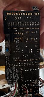
Rückseite einer Leiterplatte mit Beschriftung
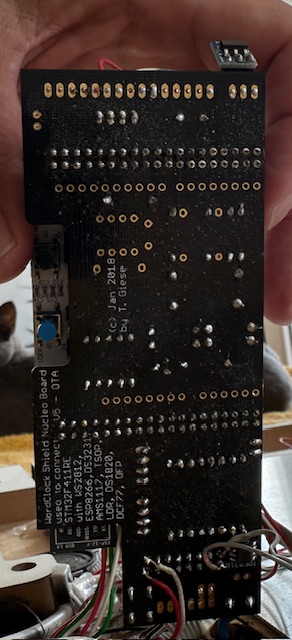
(c) Jan 2018 by T. Giese used to connect: Nucleo Board U5 with WS2812B, DS3231, ESP8266, DS18B20, AMS1117, DS1820, DCF77, DFROBOT
in „WordClock mit WS2812“ · Projekte & Code · · Platinenfotos
-
Bild
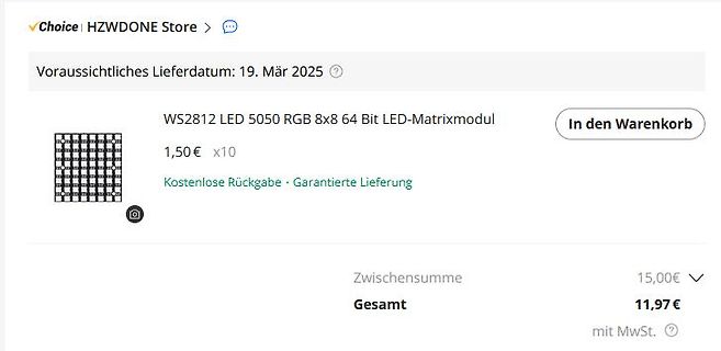
Screenshot eines Online-Shops für ein LED-Matrixmodul
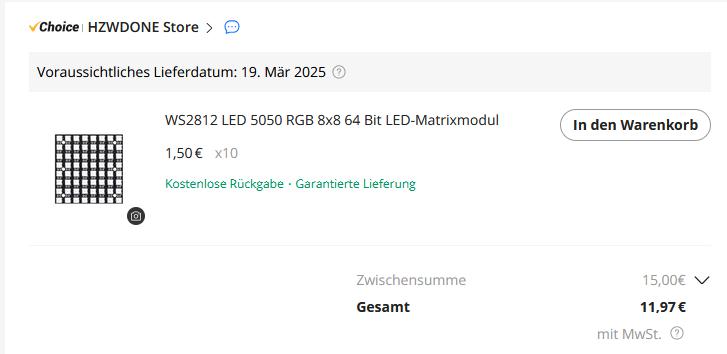
Choice HZWDONE Store > Voraussichtliches Lieferdatum: 19. Mär 2025 WS2812 LED 5050 RGB 8x8 64 Bit LED-Matrixmodul 1,50€ x10 Kostenlose Rückgabe · Garantierte Lieferung In den Warenkorb Zwischensumme 15,00€ Gesamt 11,97€ mit MwSt.
in „China SUPER Bauteile-Schnäppchen Thread [V4]“ · Markt · · Screenshots
-
PDF
Pixel_Platine.PDF
C3 VCC R1 VCC 150R 100n IC1 J2 J1 4 3 1 3 5 NC VCC 2 2 VDD DI 2 6 VSS DO 1 3 1 WS2812 SIL-100-03 SIL-100-03 GND GND
in „ws2812 mit atmega32“ · Mikrocontroller und Digitale Elektronik ·
-
Bild
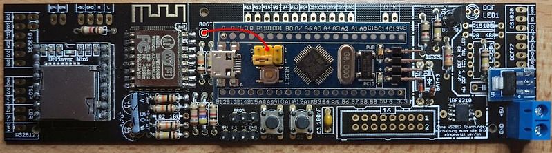
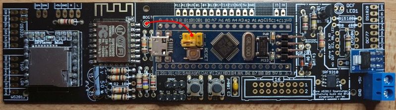
Bestückte Leiterplatte mit Mikrocontroller und DFPlayer Mini
A6, A5, A4, A3, A2, A1, AO, C1, C13, UB, DCF, LED1, DS1820, BS7, BAT43, IRF9310, C3 100nF, R2 10R, WS2812, GND, +5V
in „WordClock mit WS2812“ · Projekte & Code · · Platinenfotos
-
Bild
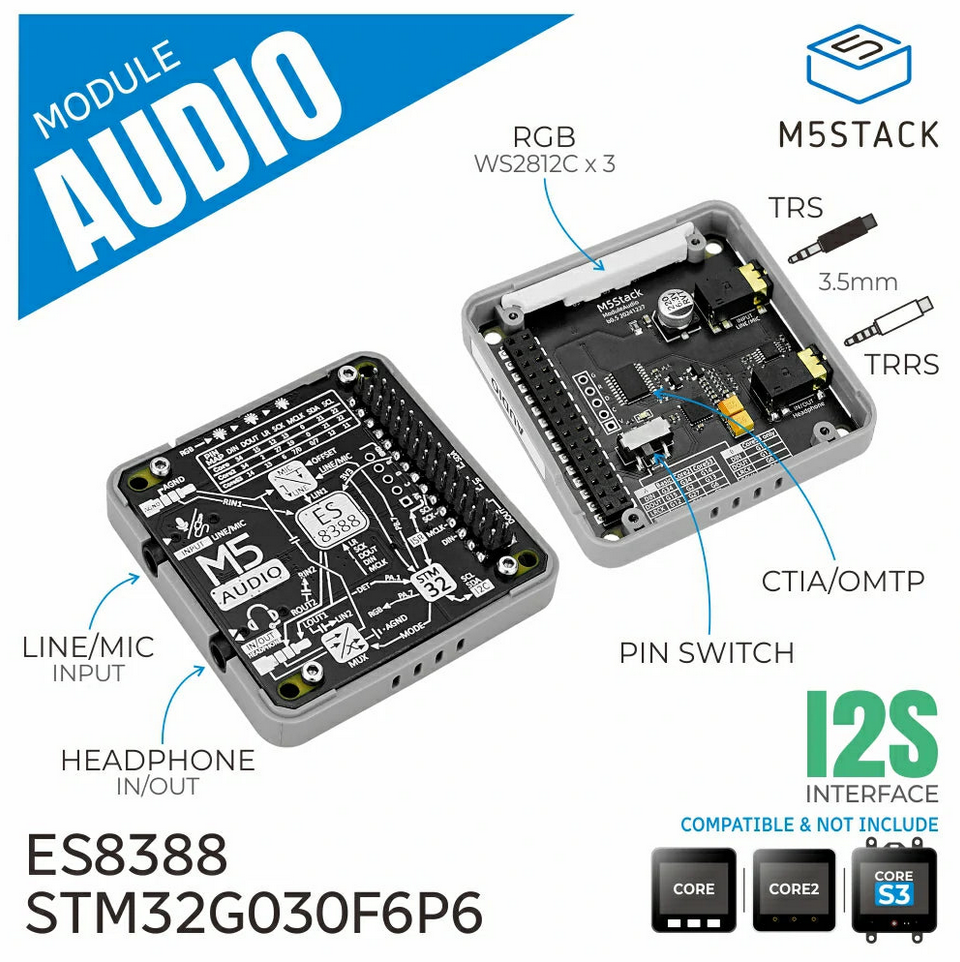
M5Stack Audio Modul mit Komponentenbeschriftung
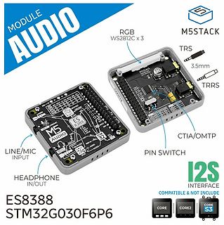
MODULE AUDIO M5STACK RGB WS2812C x 3 TRS 3.5mm TRRS PIN SWITCH CTIA/OMTP LINE/MIC INPUT HEADPHONE IN/OUT ES8388 STM32G030F6P6 I2S INTERFACE COMPATIBLE & NOT INCLUDE CORE CORE2 CORE S3
in „Neue Bauteile: DB9-Stecker mit Push-Pull, m5Stack-Module, Kelvinklemmen uvam“ · Mikrocontroller und Digitale Elektronik · · Fotos
-
Bild
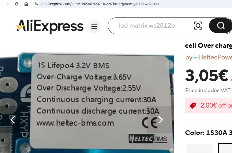
Screenshot einer AliExpress Produktseite für ein BMS
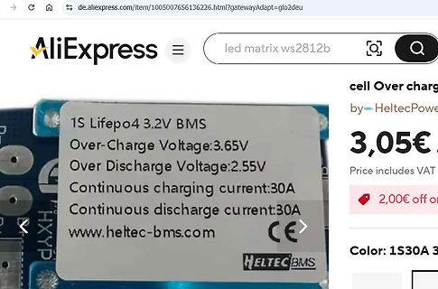
AliExpress led matrix ws2812b 1S Lifepo4 3.2V BMS Over-Charge Voltage:3.65V Over Discharge Voltage:2.55V Continuous charging current:30A Continuous discharge current:30A www.heltec-bms.com CE HELTEC BMS 3,05€ Price includes
in „4s LiFePO4: Schutzschaltung (BMS) mit 3,0V/3,5V gesucht“ · Analoge Elektronik und Schaltungstechnik · · Screenshots
-
Bild
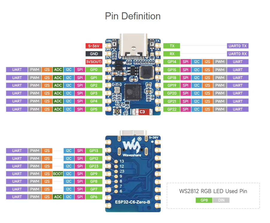
Pin-Definitionen für ESP32-C6-Zero-B Mikrocontroller
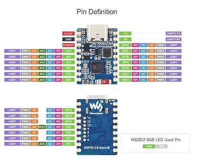
UARTO RX 3V3(OUT) SPI I2C PWM GP0 GP1 GP2 GP3 GP4 GP5 GP12 GP13 GP23 GP9 GP8 GP7 GP6 ESP32-C6-Zero-B WS2812 RGB LED Used Pin GP8 DIN
in „Arduino Uno Q-Preiserhöhung, Mikrocontroller mit Klasse D-Verstärker, OnSemi X Synaptics uvam“ · Mikrocontroller und Digitale Elektronik · · Screenshots
-
Bild
Software-Dialog zur Bearbeitung eines Schaltplansymbols
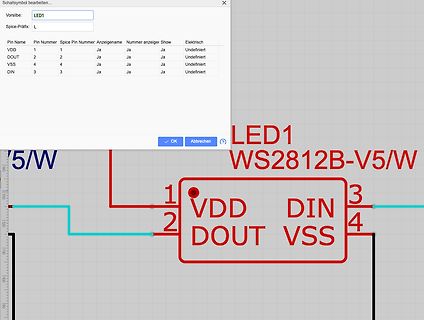
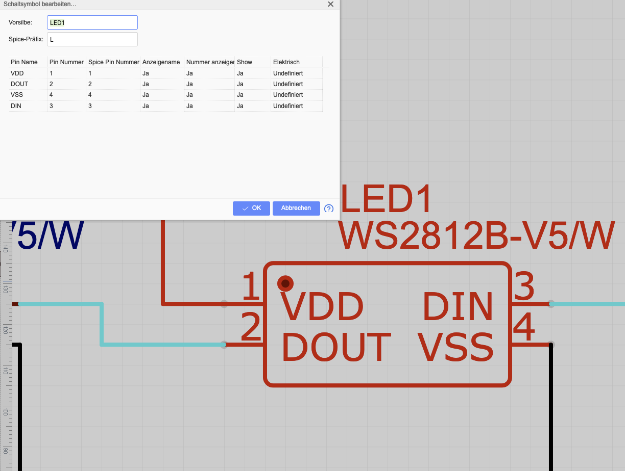
2 Ja Ja Ja Undefiniert VSS 4 4 Ja Ja Ja Undefiniert DIN 3 3 Ja Ja Ja Undefiniert OK Abbrechen LED1 WS2812B-V5/W 1 VDD 3 2 DOUT DIN 4 VSS
in „Platine mit LEDs (WS2812B V5) funktionert nicht“ · Platinen · · Screenshots
-
Bild
Microchip Studio IDE mit C-Quellcode und Build-Ausgabe
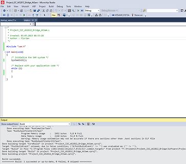
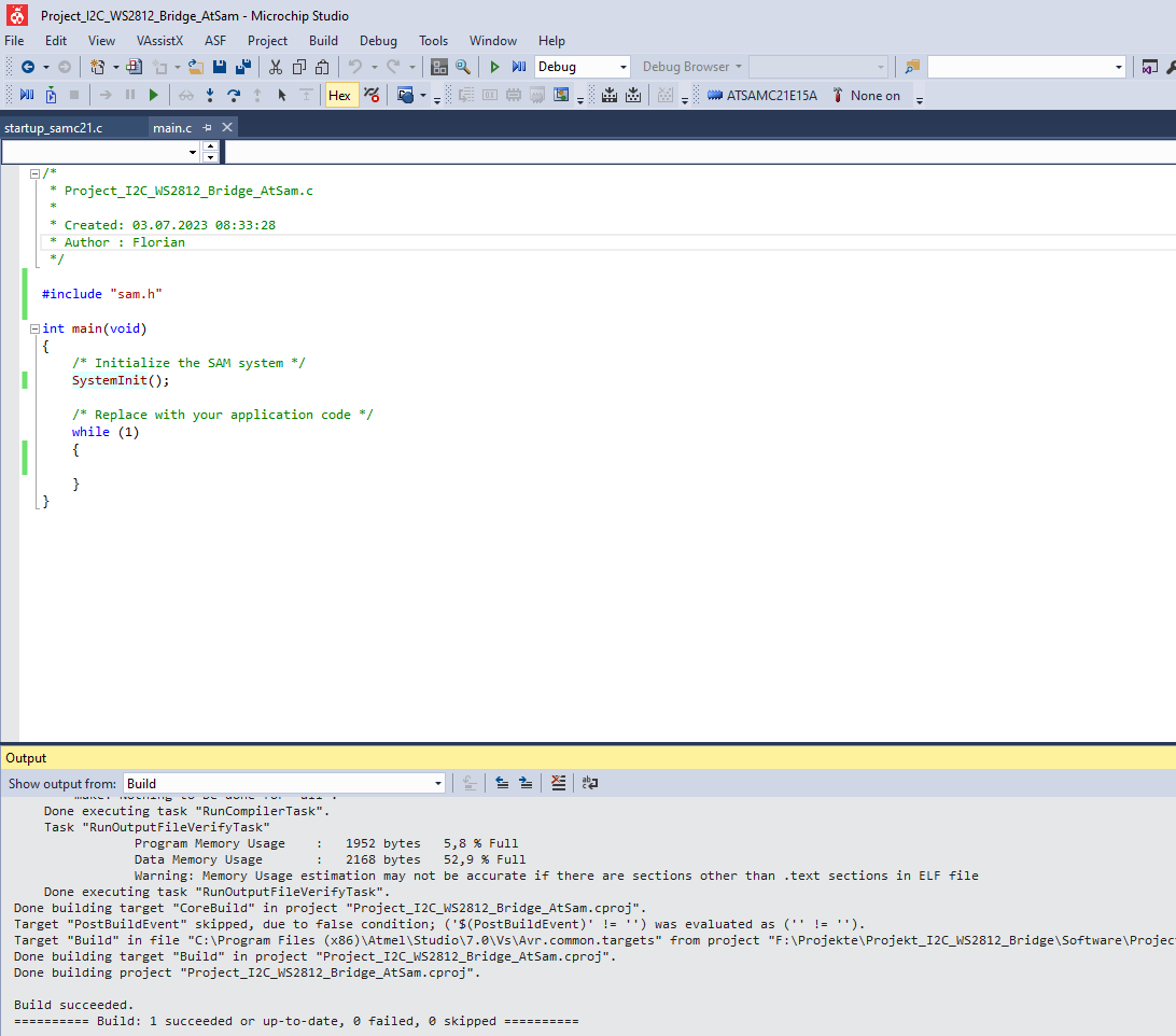
Project_I2C_WS2812_Bridge_AtSam.c - Microchip Studio #include "sam.h" int main(void) { /* Initialize the SAM system */ SystemInit(); /* Replace with your application code */ while (1) { } } Output Build Done executing
in „Unrealistische Recourcenauslastung bei leerem Projekt“ · Mikrocontroller und Digitale Elektronik · · Screenshots
-
Bild
Software-Interface eines STM32 Firmware-Updates
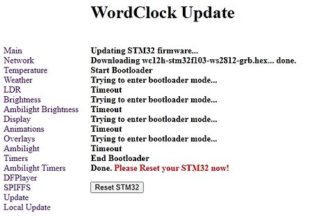
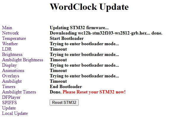
WordClock Update Main Updating STM32 firmware... Network Downloading wc12h-stm32f103-ws2812-grb.hex... done. Temperature Start Bootloader Weather Trying to enter bootloader mode... LDR Timeout Brightness Trying to enter bootloader mode... Ambilight Brightness Timeout Display Trying to enter
in „WordClock mit WS2812“ · Projekte & Code · · Screenshots
-
Bild
Software-Interface für STM32 Firmware-Update
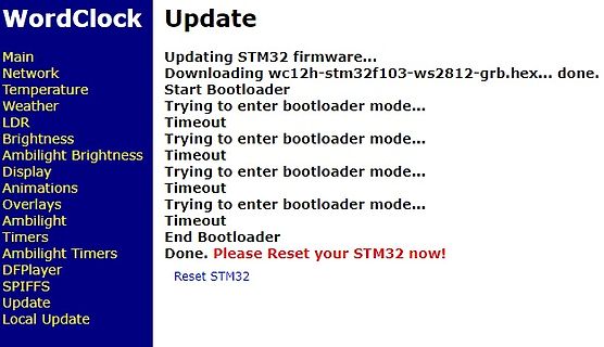
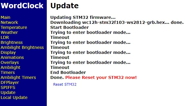
DFPlayer SPIFFS Update Local Update Update Updating STM32 firmware... Downloading wc12h-stm32f103-ws2812-grb.hex... done. Start Bootloader Trying to enter bootloader mode... Timeout Trying to enter bootloader mode... Timeout Trying to enter bootloader mode... Timeout Trying to enter bootloader mode.
in „WordClock mit WS2812“ · Projekte & Code · · Screenshots
-
Bild
Software-Menü für WordClock Projekt
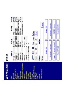
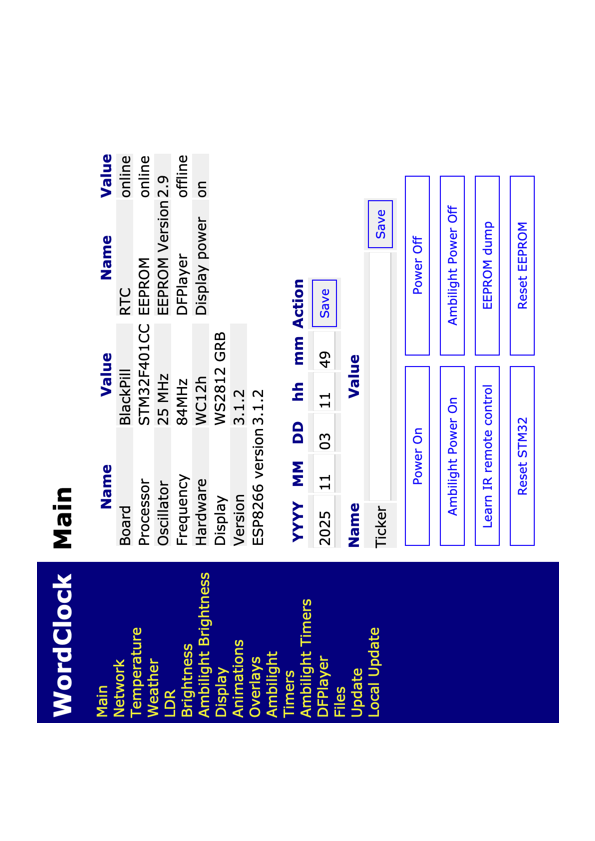
Update Main Name Value RTC online Processor STM32F401CC EEPROM online Oscillator 25 MHz 84MHz Hardware WS2812 GRB Display 3.1.2 Version ESP8266 version 3.1.2 YYYY MM DD hh mm Action 2025 11 03 11 49 Save Ticker Power On Ambilight Power On Learn IR remote control Power Off Ambilight Power Off EEPROM dump
in „WordClock mit WS2812“ · Projekte & Code · · Screenshots
-
Bild
Webinterface einer WordClock mit Systemstatus und Einstellungen
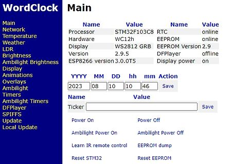
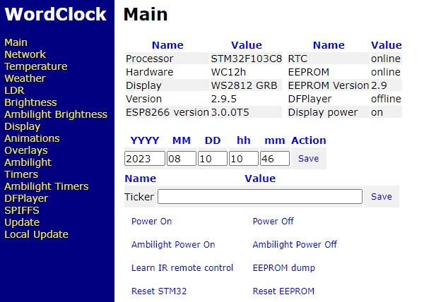
Main Main Name Value Name Value Processor STM32F103C8 RTC online Hardware WC12h EEPROM online Display WS2812 GRB EEPROM Version 2.9 Version 2.9.5 DFPlayer offline ESP8266 version 3.0.0T5 Display power on YYYY MM DD hh mm Action 2023 08 10 10 46 Save Name Value Ticker Save Power On Power Off Ambilight Power
in „WordClock mit WS2812“ · Projekte & Code · · Screenshots
-
Bild
I2C Joystick 2 Unit STM32G030 Produktseite
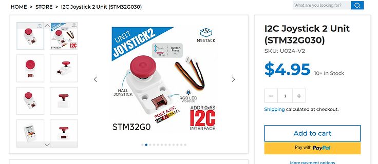
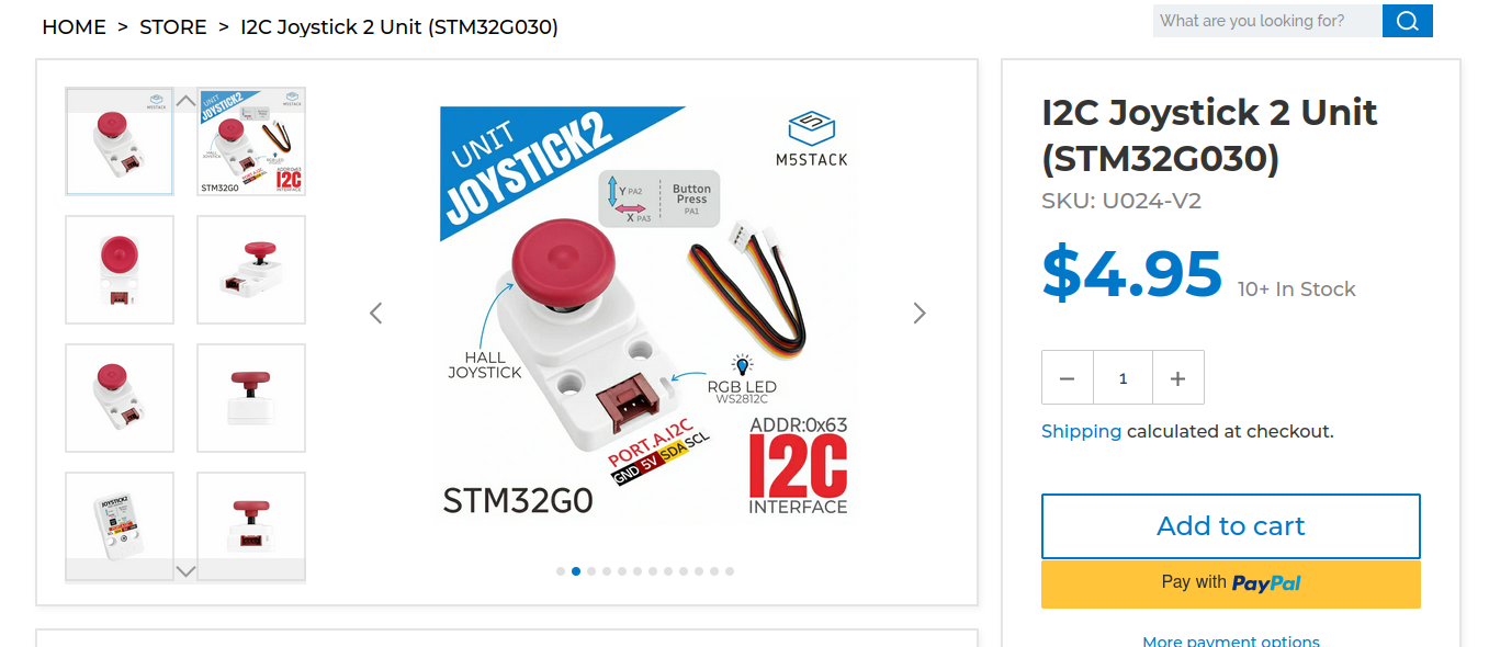
$4.95 10+ In Stock UNIT JOYSTICK2 M5STACK STM32G0 Y PA2 Button Press PA1 X PA3 HALL JOYSTICK RGB LED WS2812C PORT A, I2C GND 5V SDA SCL ADDR:0x63 I2C INTERFACE STM32G0 Add to cart Pay with PayPal
in „Neue Bauteile: STM-Drohnenkit, intelligente Steckverbinder, Stromsensoren und mehr“ · Mikrocontroller und Digitale Elektronik · · Screenshots
-
Bild
Webinterface einer WordClock Steuerung
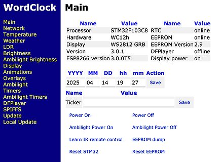
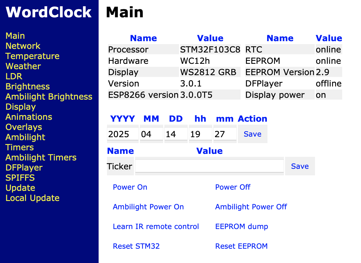
Ambilight Timers DFPlayer SPIFFS Update Local Update Processor STM32F103C8 Hardware WC12h Display WS2812 GRB Version 3.0.1 ESP8266 version 3.0.0T5 RTC online EEPROM online EEPROM Version 2.9 DFPlayer offline Display power on YYYY MM DD hh mm Action 2025 04 14 19 27 Save Name Value Ticker Save Power
in „WordClock mit WS2812“ · Projekte & Code · · Screenshots
-
Bild
Abfotografierter Bildschirm einer Web-Oberfläche für ein STM32-Projekt
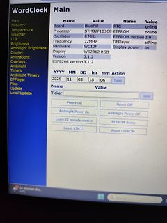
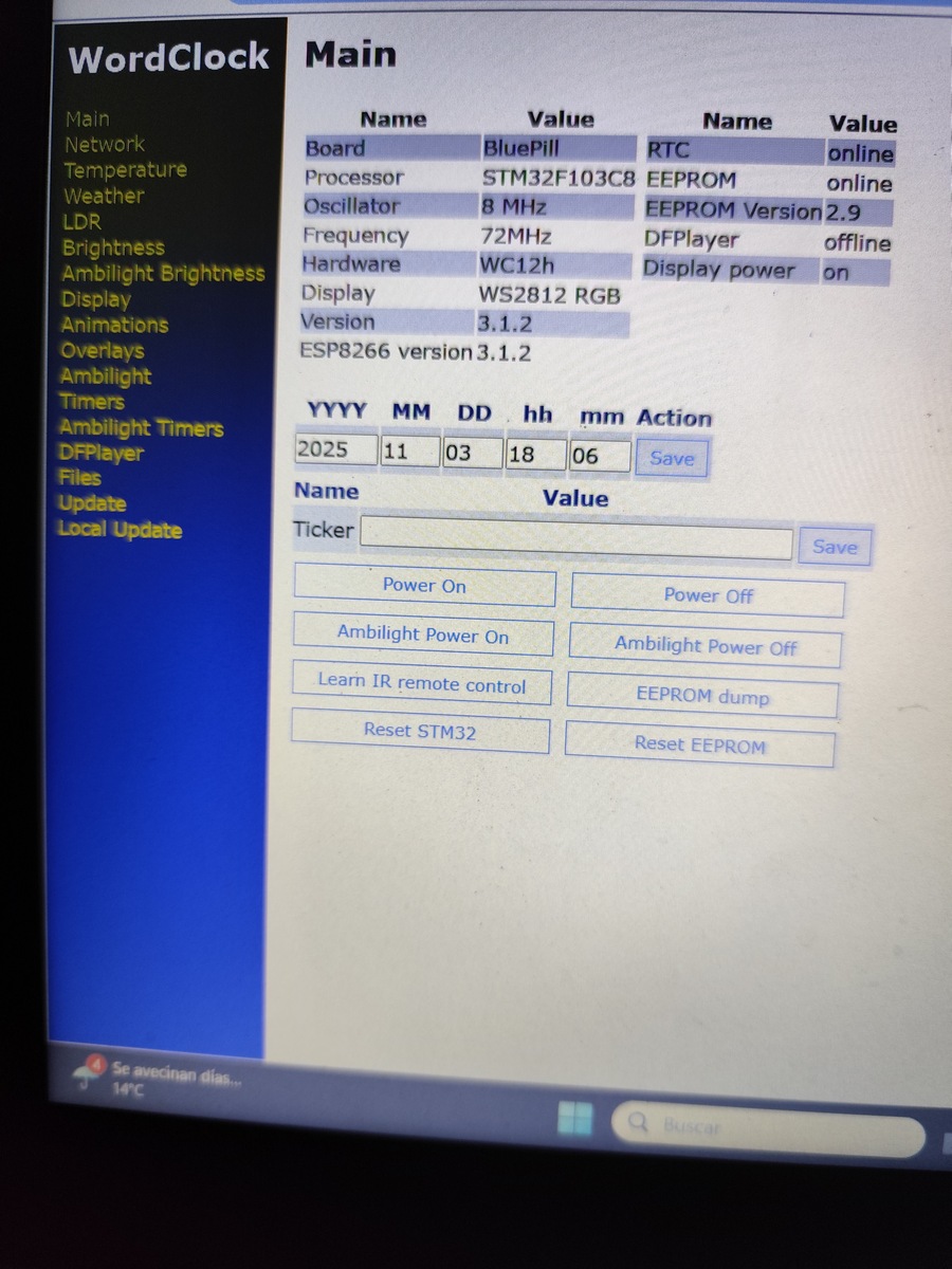
8 MHz EEPROM Version 2.9 Frequency 72MHz DFPlayer offline Hardware WC12h Display power on Display WS2812 RGB Version 3.1.2 ESP8266 version 3.1.2 YYYY MM DD hh mm Action 2025 11 03 18 06 Save Name Value Ticker Save Power On Power Off Ambilight Power On Ambilight Power Off Learn IR remote control EEPROM
in „WordClock mit WS2812“ · Projekte & Code · · Fotos
-
Bild
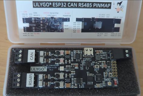
Lilygo ESP32 CAN RS485 Modul in Verpackung
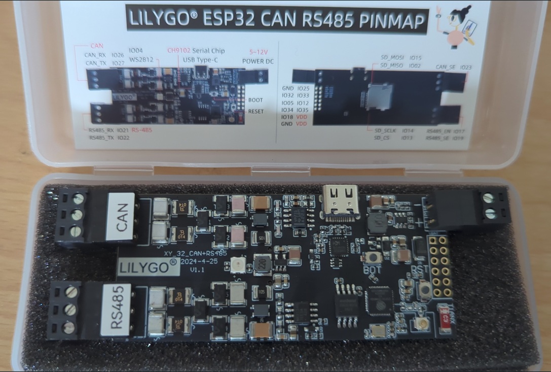
LILYGO ESP32 CAN RS485 PINMAP CAN CAN_RX IO26 CAN_TX IO27 1004 WS2812 CH9102 Serial Chip USB Type-C 5-12V POWER DC SD_MOSI IO15 SD_MISO IO02 CAN_SE IO23 SD_SCLK IO14 SD_CS IO13 RS485_EN IO17 RS485_SE IO19 RS485_RX IO21 RS485_TX IO22 GND IO25 IO32 IO33 IO05 IO12 IO34
in „[V] diverse Elektronikartikel bzw. Sammelsurium“ · Markt · · Platinenfotos
-
Datei
pins.txt
C11 D5 -> B6 D6 -> E5 D7 -> E6 HSYNC -> A4 VSYNC -> B7 PCLK -> A6 I2C SCL -> B8 SDA -> B9 Ausgaenge WS2812 -> B0 IR -> E9 Beliebige Connections: FID -> E15 -> A2 RESETB -> E14 -> D1 VBLK -> E13 -> E12 AVID -> E12 -> E11 PDN -> E11 -> E14
in „Ambilight mit STM32F4discovery und TVP5150AM1“ · Mikrocontroller und Digitale Elektronik ·
-
Bild
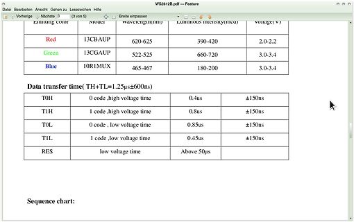
Tabelle mit technischen Daten zu Farben und Übertragungszeiten
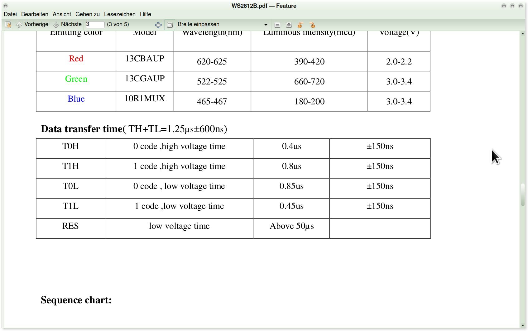
WS2812B.pdf - Feature Red 13CBAUP 620-625 390-420 2.0-2.2 Green 13CGAUP 522-525 660-720 3.0-3.4 Blue 10R1MUX 465-467 180-200 3.0-3.4 Data transfer time( TH+TL=1.25µs±600ns) T0H 0 code, high voltage time
in „RGB Led Band von Action“ · Mikrocontroller und Digitale Elektronik · · Screenshots
-
Bild
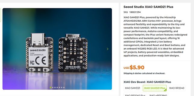
Seeed Studio XIAO SAMD21 Plus Mikrocontroller
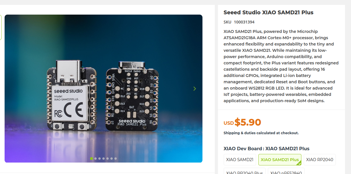
additional GPIOs, integrated Li-ion battery management, dedicated Reset and Boot buttons, and an onboard WS2812 RGB LED. It is ideal for advanced IoT projects, battery-powered wearables, embedded applications, and production-ready SoM designs. USD $5.90 XIAO SAMD21 XIAO SAMD21 Plus XIAO RP2040
in „XIAO Plus-Varianten, große Politik, CartoType mit LLM und anderes mehr“ · Mikrocontroller und Digitale Elektronik · · Screenshots
-
Bild
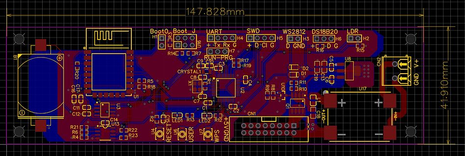
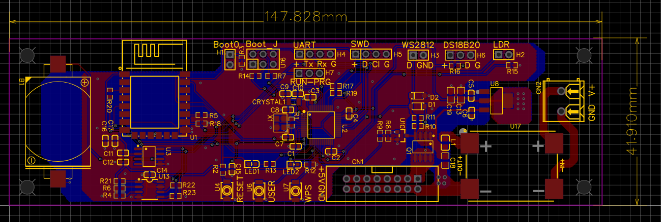
PCB-Layout einer Mikrocontroller-Platine
147.828mm 41.910mm Boot0 Boot J UART H4 H5 H3 H6 H2 SWD D C I G D GND D G LDR WS2812 DS18B20 R14 R7 R15 R20 C7 C16 R5 R18 U1 CRYSTAL C8 C9 C3 R17 R19 C11 C12 C14 U3 R21 R6 R4 R22 R23 U13 LED1 R13 LED2 R2 R12 C1 C2 C18 U4 RESET U6 USER U7 WPS 5V GND CN1 CN2 U2 U17 GND V+
in „WordClock mit WS2812“ · Projekte & Code · · Layouts
-
PDF
Flashen_STM32MiniBoard.pdf
anklicken: „Target“ und „Program & Verify“ anklicken: [2] Hex-Datei auswählen (im Beispiel: „Standard“-WS2812) und auf „Öffnen“ klicken: Flashen mit „Start“ beginnen: [3] Erfolgreiches Flashen wird im unteren Fenster angezeigt: Zum Abschluss ST-Link trennen: Fertig! [4]
-
Bild
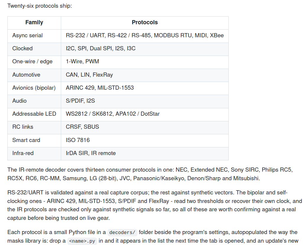
Tabelle mit Kommunikationsprotokollen nach Familien
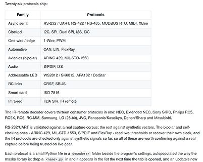
Automotive CAN, LIN, FlexRay Avionics (bipolar) ARINC 429, MIL-STD-1553 Audio S/PDIF, I2S Addressable LED WS2812 / SK6812, APA102 / DotStar RC links CRSF, SBUS Smart card ISO 7816 Infra-red IrDA SIR, IR remote The IR-remote decoder covers thirteen common protocols in one: NEC, Extended NEC, Sony SIRC, Philips
in „Neuer Desktop für Raspberry Pi, große Politik, neue Messtechnik uvam“ · Mikrocontroller und Digitale Elektronik · · Screenshots
-
Bild
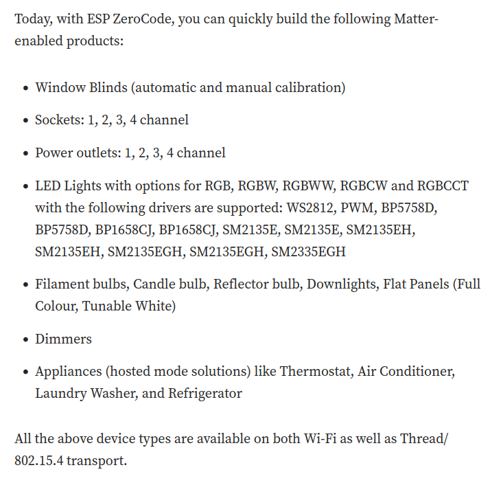
Liste von Matter-fähigen Produkten mit ESP ZeroCode
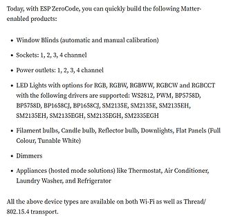
Lights with options for RGB, RGBW, RGBWW, RGBCW and RGBCT with the following drivers are supported: WS2812, PWM, BP5758D, BP5758D, BP1658CJ, BP1658CJ, SM2135E, SM2135E, SM2135EH, SM2135EH, SM2135EGH, SM2135EGH, SM2335EGH • Filament bulbs, Candle bulb, Reflector bulb, Downlights, Flat Panels (Full Colour
in „Arduino Nano Matter, ESP-Zerocode und mehr“ · Mikrocontroller und Digitale Elektronik · · Screenshots
-
Bild
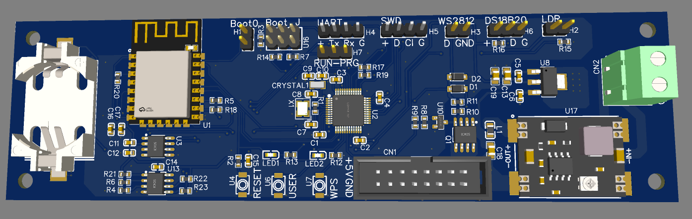
CAD-Ansicht eines Leiterplatten-Layouts
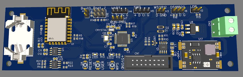
Boot0, Boot J, HART, SWD, WS2812, DS18B20, LDP, H1, H4, H5, H3, H2, U16, R14, R7, R17, R19, R15, R16, D, C, I, G, GND, U8, C5, C15, C19, D2, D1, C16, R20, C7, C9, C10, C3, C8, LX, U2, C4, U1, R5, R18, R8, R9, U10, R11, R10, C6,
in „WordClock mit WS2812“ · Projekte & Code · · Layouts
-
Bild
Produktseite Wi-Fi HaLow Module für Seeed Studio XIAO
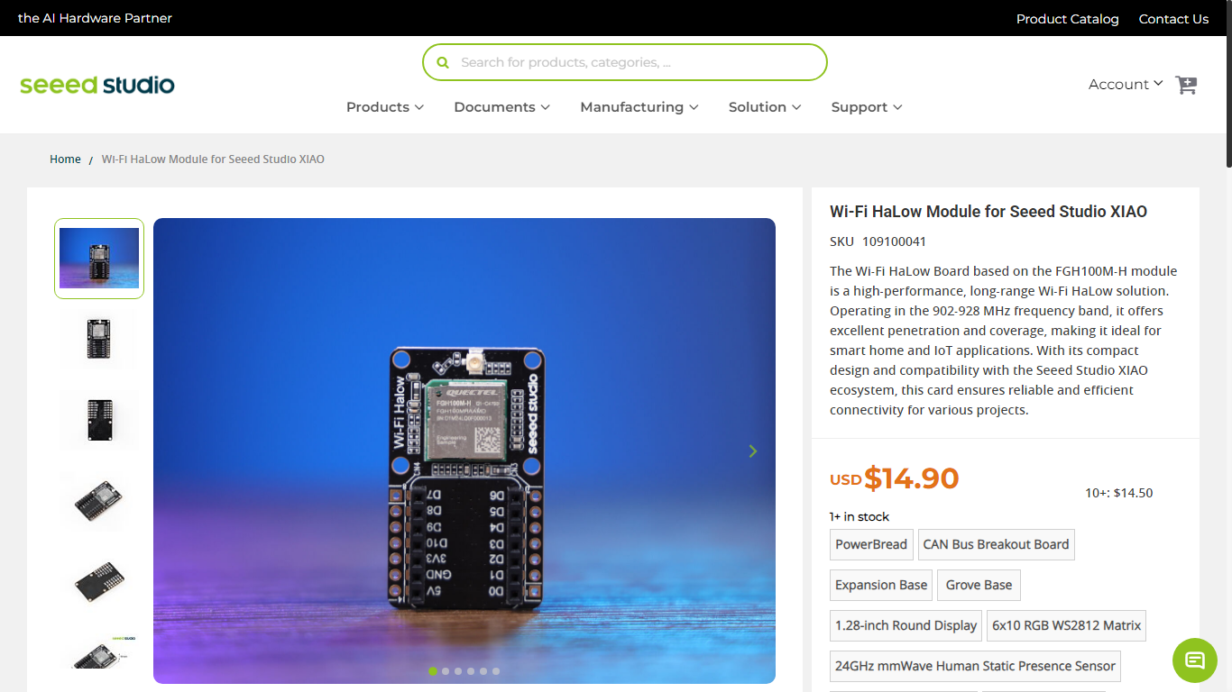
stock PowerBread CAN Bus Breakout Board Expansion Base Grove Base 1.28-inch Round Display 6x10 RGB WS2812 Matrix 24GHz mmWave Human Static Presence Sensor
in „HCI-Kommandos im ESP32, neue Mikrocontroller und Programmierwerkzeuge“ · Mikrocontroller und Digitale Elektronik · · Screenshots
-
Bild
Blockschaltbild einer Strom- und Steuerplatine
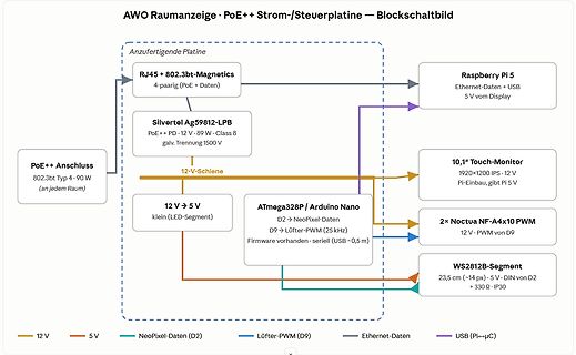
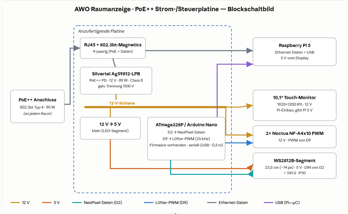
Lüfter-PWM (25 kHz) Firmware vorhanden · seriell (USB ~0,5 m) 2x Noctua NF-A4x10 PWM 12 V · PWM von D9 WS2812B-Segment 23,5 cm (~14 px) · 5 V · DIN von D2 + 330 Ω · IP30 12 V 5 V NeoPixel-Daten (D2) Lüfter-PWM (D9) Ethernet-Daten USB (Pi->µC)

in „Projekt AWO-Raumanzeige — Hilfe/Umsetzung einer PoE++ Strom- & Steuerplatine gesucht (Raspberry Pi)“ · Platinen · · Diagramme
-
Datei
main.c
I2C1 SCL=PB6 SDA=PB7 | | * | LDR | ADC ADC1_IN14=PC4 | ADC ADC1_IN5=PA5 | ADC ADC1_IN5=PA5 | | * | WS2812 / SK6812 | TIM3/DMA1 PC6 | TIM3/DMA1 PB1 | TIM1/DMA1 PA8 | | * | APA102 | SPI2/DMA1 SCK=PB13 MOSI=PB15 | SPI2/DMA1 SCK=PB13 MOSI=PB15 | SPI2/DMA1 SCK=PB13 MOSI=PB15 | | * | Power switch | GPIO PC8