220AC, TO-263AB IF(AV) 8.0 A V 50 V to 600 V Molding compound meets UL 94V-0 flammability rating RRM Base P/N-E3 - RoHS-compliant, commercial grade IFSM 125 A Base P/NHE3 - RoHS-compliant, AEC-Q101 qualified trr 35 ns, 50 ns Terminals: Matte tin plated leads, solderable per VF 0.95 V, 1.30 V, 1.50 V J-STD
Advantages 1. High input impedance, Voltage controlled device, Easy to drive. To maintain on-state, base drive current which is 1/5 or 1/10 of collector current is required, and larger reverse base drive current is needed for the high speed turn-off for the current con- trolled device, BJT. Due to these characteristics base drive circuit design becomes compli- Rev C, November 1999 5 cated, and becomes expensive. On the other hand, voltage controlled device MOSFET is a switching device which is driven by channel at the
1. High input impedance - voltage controlled device - easy to drive. To maintain the on-state, a base drive current which is 1/5th or 1/10th of collector current is required for the current controlled device (BJT). And also a larger reverse base drive current is needed for the high speed turn-off of
Die Kombination R19 und C9 ist Mist. Am besten R19 fest auf ca. 20...30k, dem entsprechen R21-R23 auf Verstärkungsfaktor 6 anpassen. Die soll Spannung dann variieren zwischen 0..5V statt 5V fest. C6 und C7 1nF...22nF probieren, oder schnellere OPV statt LM324. Die minimale Last vlt. auf 5mA
gehen über je 0,55 Ohm nach GND - Kurzschluss. Q5 kommt von +5Volt und liefert irgendwas zu den Basen der Endstufe, jedenfalls nicht genug, mehr als knapp 4V am Ausgang zu erzeugen. Nachvollziehbare Regelkreise, wo sind die?
Ich hab grad mal angefangen Guidos Code zu inspizieren: http://www.ispf.de/files/propellerclock/base_main.c Hm. kann das sein dass das garkein echter Manchester code ist? In der Low Phase wird an T_Out das Datenbit übergeben, das grad an der Reihe ist. In der High Phase wird nun dieses Databit
hatte damals 0.5mm 100 : 0.25mm 150 Prim./Sek. bei ca. 7cm Kerndurchmesser und dabei ein optimum bei 21KHz. Damit gehen gehen problemlos 9600Baud übder den Draht und meine nächste Version wird noch höher getaktet werden.. Gruß, Guido (passwort vergessen)
the ER● ● ● EC with ER GH housing and ER-AK, ER-AH or ER-AB with the ER EC fan insert. Air volume – base load 30 m³/h for continuous ope●ation ● ● ● Air volume of the base load and full load levels can be s●t ● ● Additional air volumes that can be set ● ●*** ● in base load: 20 m³/h, 40 m³/h, 60 m³/h or
nix... arm9 oder xscale bei 500Mhz ja ok wenn man ein richtig schnelles interface hat... im base-band speich ein demoduliertes signal richtig in ein digitales zu verwandeln ist mit nem korellationsdetector super machbar... einfach as spektrum vom gefragten puls spiegeln und mit dem eingangspuls
zu : >Korrelation ist besser statt hohe Sendeleitsung!!! >Autor: Franz >Datum: 04.08.2006 15:21 >Ich habe mit soetwas bereis sehr gute praktische Erfahrungen gemacht. >Als Sender habe ich einen Quartzoszillator >und als Empfänger habe ich einen einfachen Geradeausempfänger(mit >Quartz
INTERNATIONAL IEC STANDARD 62056-21 First edition 2002-05 Electricity metering – Data exchange for meter reading, tariff and load control – Part 21: Direct local data exchange This English-language version is derived from the original
high quality volume level adjustment and mute function. The scheme of the circuit is shown in Figure 21. FROM DAC VIA LINEOUT HPOUT VMID Figure 21 Headphone Amplifier Schematic LHPOUT and RHPOUT volumes can be independently adjusted under software control using the LHPVOL[6:0] and RHPVOL[6:0] bits respectively
. kann mit einem Löttemperaturen. Umbausatz in eine COD-Version umgerüstet werden. 2. Lötkolben LR-21 antistatic (24V/50W). Der Lötkolben LR 21 * ist standardmäßig mit einem temperaturbeständigem Silikon- 3. Leistungsstarkes Heizelement. Isolation 500V 4. Auswahl von 22 WELLER "Longlife"- Lötspitzen.
to trigger it to the ON and shorting the base of the 2N3055 to condition. This could be done with a 2N5811 PNP transistor, as shown ground, which keeps the load OFF. When a below in figure 21. magnet is brought near the Hall switch, it turns ON, shorting the base of the 2N5812 to When the Hall switch is turned ON, 9 mA of base current flows into ground and turning it OFF. This allows: the 2N5811, thereby saturating it and allowing it to supply 80 mA of current
to trigger it to the ON and shorting the base of the 2N3055 to condition. This could be done with a 2N5811 PNP transistor, as shown ground, which keeps the load OFF. When a below in figure 21. magnet is brought near the Hall switch, it turns ON, shorting the base of the 2N5812 to When the Hall switch is turned ON, 9 mA of base current flows into ground and turning it OFF. This allows: the 2N5811, thereby saturating it and allowing it to supply 80 mA of current
to trigger it to the ON and shorting the base of the 2N3055 to condition. This could be done with a 2N5811 PNP transistor, as shown ground, which keeps the load OFF. When a below in figure 21. magnet is brought near the Hall switch, it turns ON, shorting the base of the 2N5812 to When the Hall switch is turned ON, 9 mA of base current flows into ground and turning it OFF. This allows: the 2N5811, thereby saturating it and allowing it to supply 80 mA of current
to trigger it to the ON and shorting the base of the 2N3055 to condition. This could be done with a 2N5811 PNP transistor, as shown ground, which keeps the load OFF. When a below in figure 21. magnet is brought near the Hall switch, it turns ON, shorting the base of the 2N5812 to When the Hall switch is turned ON, 9 mA of base current flows into ground and turning it OFF. This allows: the 2N5811, thereby saturating it and allowing it to supply 80 mA of current
to trigger it to the ON and shorting the base of the 2N3055 to condition. This could be done with a 2N5811 PNP transistor, as shown ground, which keeps the load OFF. When a below in figure 21. magnet is brought near the Hall switch, it turns ON, shorting the base of the 2N5812 to When the Hall switch is turned ON, 9 mA of base current flows into ground and turning it OFF. This allows: the 2N5811, thereby saturating it and allowing it to supply 80 mA of current
to trigger it to the ON and shorting the base of the 2N3055 to condition. This could be done with a 2N5811 PNP transistor, as shown ground, which keeps the load OFF. When a below in figure 21. magnet is brought near the Hall switch, it turns ON, shorting the base of the 2N5812 to When the Hall switch is turned ON, 9 mA of base current flows into ground and turning it OFF. This allows: the 2N5811, thereby saturating it and allowing it to supply 80 mA of current
to trigger it to the ON and shorting the base of the 2N3055 to condition. This could be done with a 2N5811 PNP transistor, as shown ground, which keeps the load OFF. When a below in figure 21. magnet is brought near the Hall switch, it turns ON, shorting the base of the 2N5812 to When the Hall switch is turned ON, 9 mA of base current flows into ground and turning it OFF. This allows: the 2N5811, thereby saturating it and allowing it to supply 80 mA of current
Led Alias Portd.7 Led = 0 'Dim Button As Bit 'Button = 1 If Usesdcard = 1 Then $include "Config_MMC.bas" If Gbdriveerror = 0 Then ' Include AVR-DOS Configuration and library $include "Config_AVR-DOS.BAS" Btemp1 = Initfilesystem(1) If Btemp1 <> 0 Then Flash = 5 Gosub Flash Sdpresent = 0 'Wait 5 Else Ltemp1
verlöten, folgende fünf PINs sind ausreichend: PIN 3 (EN), PIN 8 (VCC), PIN 15 (Ground), PIN 21 (RxD0) und PIN 22 (TxD0). Auf dem Bild sind diese PINs mit grüner Farbe beschriftet. Umbau (1a) Alle anderen PINs, PIN 16 (GPIO 15), PIN 19 (GPIO 4) und PIN 20 (GPIO 5), die blau beschriftet sind,
Habe so 1970 mit Spiegelfrequenz (also -21,4 MHz) und einem normalen UKW-Radio (später ein Sony Captain 55), das auf der Flanke des FM-Demodulators locker AM machte, angefangen Flugfunk zu hören. D.h. unser Approach auf 118,05 lag so auf 96,5
* Hack in jede UNTERNEHMEN WEBSITE * Hack in jede REGIERUNG AGENCY WEBSITE * Hack in jede DATA BASE * Hack PAYPAL ACCOUNT * Hack WORDPRESS Blogs * SERVER CRASHED Hack * Unaufführbare Ip etc * Wir können LOST FILES UND DOKUMENTE wiederherstellen, egal wie lange sie fehlen HINWEIS Wenn Sie den
buffers are implemented as circular increasing modulo buffers, both <span class=Computer><i>coeffsBase</i></span> and <span class=Computer><i>delayBase</i></span> must be aligned to a zero power of two address (<span class=Computer><i>coeffsEnd</i></span> and <span class=Computer><i>delayEnd</i></span
durée l'ouverture droite que gauche de l'appareil de de10heures.Ainsienfonctionnementintermittent base. L'appareil de base doit être débranché presque toute panne prématurée se déclarera. Il avant de procéder à l'introduction ou à un estnéanmoinspossiblequ'uncomposantnetombe changement de module. La
durée l'ouverture droite que gauche de l'appareil de de10heures.Ainsienfonctionnementintermittent base. L'appareil de base doit être débranché presque toute panne prématurée se déclarera. Il avant de procéder à l'introduction ou à un estnéanmoinspossiblequ'uncomposantnetombe changement de module. La
rate in Mbps (i.e. 10Mbps, 100Mbps, and 1000Mbps) •For 10 Base-T, data is transmitted over 2 UTP (unshielded twisted pairs) using a 10MHz clock •For 100 Base-TX, data is transmitted over 2 UTP using a 125MHz clock •For 1000 Base-T data is transmitted over 4 UTP
Carsten S. (dg3ycs) 31.12.2020 21:43; Danke der info. Das heisst doch mit anderen Worten, dass es zukünftig vollkommen unmöglich ist, im Modellbaubereich selber zu eloxieren. Dazu wird rund 15%ige Schwefelsäure benötigt, geht zwar
mit Schwefelsäure anstellen kann (außer damit irgendwas zu verätzen - und das können alle Säuren, Basen können es auch).
60998-1:2004, EN 60998-2-1:2004 flammability rating UL94V-0 RoHS yes PARTNUMBERKEY TBP02P1-381-XXXX Base Number No. of Poles: Color: 02 14 BE = blue 03 15 GR = green 04 16 OR = orange 05 17 YL = yellow 06 18 GY = gray 07 19 BK = black 08 20 09 21 10 22 11 23 12 24 13 cui.com For more information, please
Funktionen? ...vielleicht ist das besser und übersichtlicher in deinen Augen? http://trouch.com/2012/08/21/webiopi-control-your-pis-gpio-with-a-browser/
> ...vielleicht ist das besser und übersichtlicher in deinen Augen? > http://trouch.com/2012/08/21/webiopi-control-your-pis-gpio-with-a-browser/ ...hmm gerade gesehen, diese Seite ist aussagekräftiger: http://webiopi.trouch.com/
Peripherals sind oft dinosaurierhaft überfrachtet, das Pinout graust die Sau. Atmels neuere ARMs (SAMD21 & Co.) machen da einen deutlich weniger angestaubten Eindruck.
klein. Schließlich hat ein LPC810 nur 4K Flash :-) https://github.com/microbuilder/LPC810_CodeBase Lothar schrieb im Beitrag #4953316: >> Einstieg mit einem kleinen ARM im DIP-Package auf Steckbrett > > DIR0_bit.P0_0 = 1; > PIN0_bit.P0_0 = 1;
ein schaltender Werkstoff? Also nicht der eigentliche Trafo,sondern der kleine Ringkern der die Basen treibt. Nur mal als alternative Quelle gedacht!
schrieb im Beitrag #3830223: > Also nicht der eigentliche Trafo,sondern der kleine Ringkern der die > Basen treibt. Das *ist* der eigentliche Trafo, das Andere ist die strom- bzw. leistungsbestimmende Drossel.
wireless connection ensures that the mobile unit consistently receives the necessary RTCM data from the base station, maintaining high-precision positioning even at a distance. [/c] ### Microchip PIC32CM * PL10 – mit AVR Dx kompatibler 32-Bitter Microchip möchte Nutzern der AVR Dx-Familie einen Weg zum
Antenne, die für die Videoübertragung im Bereich von 5-5.9GHz optimiert ist. 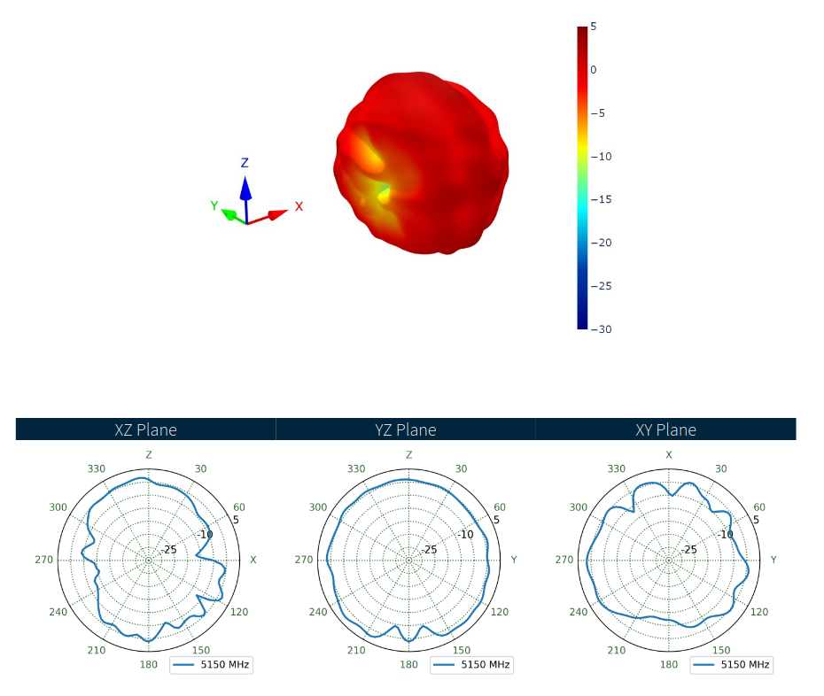 Bildquelle: Taoglas ### OSRAM SFH 7019 – Grün, Infrarot und UV-A in einer LED RGB-Dioden, die verschiedene Arten von sichtbarem Licht kombinieren, sind per Se nichts neues. OSRAM lanciert
