Drain-Source Voltage VDS 30 V Gate-Source Voltage VGS ±12 V T =25°C 5.8 Continuous Drain A D Current TA=70°C 4.9 A C Pulsed Drain Current DM 30 T =25°C 1.4 A PD W Power DissipationB TA=70°C 0.9 Junction and Storage Temperature Range TJ, STG -55 to 150 °C Thermal Characteristics Parameter Symbol Typ Max Units Maximum Junction-to-Ambient A t ≤ 10s A D RθJA 70 90 °C/W Maximum Junction-to-Ambient Steady-State 100 125 °C/W Steady-State Maximum Junction-to-Lead RθJL 63 80 °C/W Rev 8: Dec 2011 www.aosmd.com Page 1 of 5 AO3400 Electrical Characteristics (T =25°
Drain-Source Voltage VDS 30 V Gate-Source Voltage VGS ±12 V T =25°C 5.7 Continuous Drain A D Current TA=70°C 4.7 A C Pulsed Drain Current DM 30 T =25°C 1.4 A PD W Power DissipationB TA=70°C 0.9 Junction and Storage Temperature Range TJ, STG -55 to 150 °C Thermal Characteristics Parameter Symbol Typ Max Units Maximum Junction-to-Ambient A t ≤ 10s A D RθJA 70 90 °C/W Maximum Junction-to-Ambient Steady-State 100 125 °C/W Steady-State Maximum Junction-to-Lead RθJL 63 80 °C/W Rev 3: Dec 2011 www.aosmd.com Page 1 of 5 AO3400A Electrical Characteristics (T =25
Drain-Source Voltage VDS 30 V Gate-Source Voltage VGS ±12 V T =25°C 5.7 Continuous Drain A D Current TA=70°C 4.7 A C Pulsed Drain Current DM 30 T =25°C 1.4 A PD W Power DissipationB TA=70°C 0.9 Junction and Storage Temperature Range TJ, STG -55 to 150 °C Thermal Characteristics Parameter Symbol Typ Max Units Maximum Junction-to-Ambient A t ≤ 10s A D RθJA 70 90 °C/W Maximum Junction-to-Ambient Steady-State 100 125 °C/W Steady-State Maximum Junction-to-Lead RθJL 63 80 °C/W Rev 3: Dec 2011 www.aosmd.com Page 1 of 5 AO3400A Electrical Characteristics (T =25
area HEAP,NOINIT,READWRITE,ALIGN=3' ../startup_stm32f10x_hd.S:48: Error: bad instruction `__heap_base' ../startup_stm32f10x_hd.S:49: Error: bad instruction `heap_mem SPACE Heap_Size' ../startup_stm32f10x_hd.S:50: Error: bad instruction `__heap_limit' ../startup_stm32f10x_hd.S:52: Error: bad instruction
dcd 0' ../startup_stm32f10x_hd.S:69: Error: bad instruction `reserved' ../startup_stm32f10x_hd.S:70: Error: bad instruction `dcd 0' ../startup_stm32f10x_hd.S:70: Error: bad instruction `reserved' ../startup_stm32f10x_hd.S:71: Error: bad instruction `dcd 0' ../startup_stm32f10x_hd.S:71: Error: bad
Cycle-by-Cycle Peak Current Limit pulse skipping may occur. • Fast Current Sense to Output Delay • 70ns Leading Edge Blanking Ordering Information • Multi-Pulse Suppression PART PART TEMP. PKG. NUMBER MARKING RANGE (°C) PACKAGE DWG. # • Buffered Oscillator Sawtooth Output ISL6753AAZA ISL6753AAZ -40 to
Befehlssatzarchitektur angeht. Die meisten, soweit es noch aktuelle Implementierungen gibt, stammen im Kern aus den 70/80ern und wurden allenfalls mal modernisiert wie x86 oder Coldfire.
......... 70 Downloading HP PC Hardware Diagnostics UEFI by product name or number (select products only) ..................................................................................................... 70 Using
INTEGRATED CIRCUITS DATA SHEET TDA1562Q 70 W high efficiency power amplifier with diagnostic facility Preliminary specification 1998 Apr 07 File under Integrated Circuits, IC01 Philips Semiconductors Preliminary specification 70 W high efficiency
INTEGRATED CIRCUITS DATA SHEET TDA1562Q 70 W high efficiency power amplifier with diagnostic facility Preliminary specification 1998 Apr 07 File under Integrated Circuits, IC01 Philips Semiconductors Preliminary specification 70 W high efficiency
, Base and Collector and xyz means the sequence of the corresponding pin numbers. 10. The measurement for bipolar transistors is also done with common collector (emitter follower). The hFE value of High Power
und sendet deren Code an das Teilchen. Eine Variante die ich mir nur nebenbei angesehen habe ist BasCom. Die ist aber kostenpflichtig. Was ich damit sagen. Man muss kein C schreiben. Was den Speicherverbrauch angeht. Den kann man (getested) einfach senken. Viele Libs sind "universal" geschrieben
ef ldi r28, 0xFF ; 255 6e: d8 e0 ldi r29, 0x08 ; 8 70: de bf out 0x3e, r29 ; 62 72: cd bf out 0x3d, r28 ; 61 74: 0e 94 40 00 call 0x80 ; 0x80 <main> 78: 0c 94 57 00 jmp 0xae ;
TFT/Transmissive Viewing Direction 6 o’clock Connection Type COG + FPC Operation temperature -20℃ ~70℃ Storage temperature -30℃ ~80℃ Driving IC HX8340B MPU interface 16-bit /8-bit Parallel 8080 interface 1.2 Mechanical Description Item Standard Value Unit Screen size 2.0 inch Number of dots 176RGB x
TFT/Transmissive Viewing Direction 6 o’clock Connection Type COG + FPC Operation temperature -20℃ ~70℃ Storage temperature -30℃ ~80℃ Driving IC HX8340B MPU interface 16-bit /8-bit Parallel 8080 interface 1.2 Mechanical Description Item Standard Value Unit Screen size 2.0 inch Number of dots 176RGB x
Level-1-NA-UNLIM -40 to 85 LM2902N & no Sb/Br) LM324AM NRND SOIC D 14 55 TBD Call TI Call TI 0 to 70 LM324AM LM324AM/NOPB ACTIVE SOIC D 14 55 Green (RoHS CU SN Level-1-260C-UNLIM 0 to 70 LM324AM & no Sb/Br) LM324AMX NRND SOIC D 14 2500 TBD Call TI Call TI 0 to 70 LM324AM LM324AMX/NOPB ACTIVE SOIC D 14 2500 Green (RoHS CU SN Level-1-260C-UNLIM 0 to 70 LM324AM & no Sb/Br) LM324AN/NOPB ACTIVE PDIP NFF 14 25 Green (RoHS CU SN Level-1-NA-UNLIM 0 to 70 LM324AN & no Sb/Br) LM324M NRND SOIC D 14 55 TBD Call TI Call TI 0 to 70 LM324M LM324M/NOPB ACTIVE SOIC
Sense Input Voltage versus Current Sense Input Voltage V V ( ( E 70 E 70 A A L V = 15 V L TA= 25°C V 68 CC V 68 D D O O S 66 S 66 E E H H T T E 64 E 64 R R U U R 62 R 62 E E O O ,C 60 ,C 60 S -60 -40 -20 0 20 40 60 80 100 120 140 S 12 14 16 18 20 V V TA, AMBIENT TEMPERATURE
Werkstoffe & Zulassungen / material & approvals: G Eigenschaften / general specifications: Basismaterial / base material: Ferrite Arbeitstemperatur / operating temperature: -40°C - +125°C Draht / wire: Class F Umgebungstemp. / ambient temperature: -40°C - +85°C It is recommended that the temperature of the part
each wdg. N1, N2 Sättigungsstrom (je Wicklg.) / 2,2 saturation current (each wdg.)|∆L/L|<10% Isat 0,70 A max. Eigenres.-Frequenz / self-res.-fequency SRF 4 MHz typ. 1,0 Nennspannung / rated voltage U DC 80 V max. D Prüfgeräte / test equipment : E Testbedingungen / test conditions : HP 4274 Afür/for L
Serienfahrzeugen..wenn es sehr gut und fein abgestimmt ist, kann es sehr gut sein..aber auch ohne BAs ist eine perfekte Bremsung poblemlos möglich und man kann das ganze sehr viel ebsser dem untergrund anpassen was beim ABS nicht automatisch erfolgen kann..evtl mit ner Wintertaste oder so :-) Ohen
zwischen Reifen und Fahrbahn. Nicht zuletzt deswegen werden Bremsen heute so abgestimmt, daß sie ca. 70% der Bremsleistung auf der Vorderachse leisten (der andere Grund ist, daß ein Auto mit blockierten Vorderrädern geradeaus rutscht, während es sich bei blockierenden Hinterrädern unweigerlich dreht).
to indirect memory and 2 post-increment source pointer by 2 MOV Rw, Move indirect word memory by base plus constant to 4 [Rw + #data16] direct GPR MOV [Rw + #data16], Move direct word GPR to indirect memory by base plus 4 Rw constant Semiconductor Group 28 SAB 80C166W/83C166W Instruction Set Summary
-40 to 85 2806 Samples UCC3806DW ACTIVE SOIC DW 16 40 RoHS & Green NIPDAU Level-2-260C-1 YEAR 0 to 70 UCC3806DW Samples UCC3806DWG4 ACTIVE SOIC DW 16 40 RoHS & Green NIPDAU Level-2-260C-1 YEAR 0 to 70 UCC3806DW Samples UCC3806DWTR ACTIVE SOIC DW 16 2000 RoHS & Green NIPDAU Level-2-260C-1 YEAR 0 to 70 UCC3806DW Samples UCC3806J ACTIVE CDIP J 16 1 Non-RoHS SNPB N / A for Pkg Type 0 to 70 UCC3806J Samples & Green UCC3806N ACTIVE PDIP N 16 25 RoHS & Green NIPDAU N / A for Pkg Type 0 to 70 UCC3806N Samples UCC3806NG4 ACTIVE PDIP N 16 25 RoHS & Green NIPDAU N / A for Pkg Type 0 to 70 UCC3806N
for MEGA fuse
www.victronenergy.com
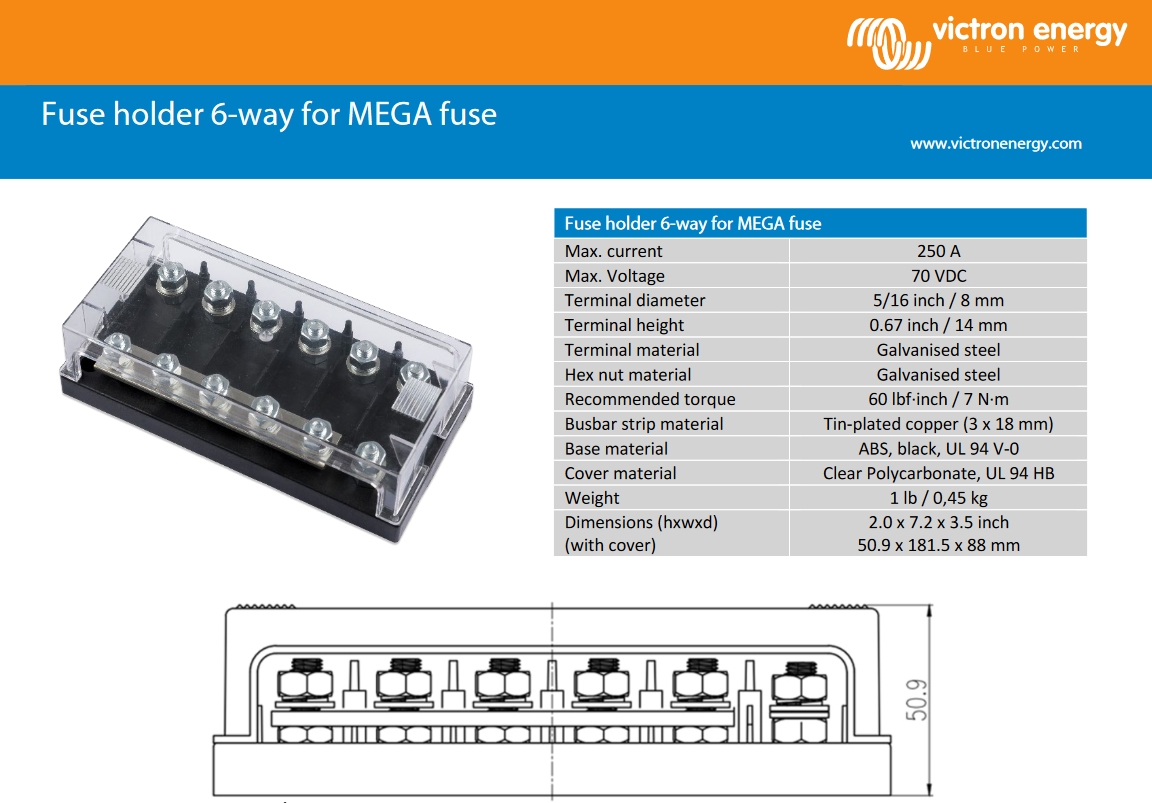
Fuse holder 6-way for MEGA fuse
Max. current 250 A
Max. Voltage 70 VDC
Terminal diameter 5/16 inch / 8 mm
Terminal height 0.67 inch / 14 mm
Terminal material Galvanised steel
Hex nut material Galvanised steel
Recommended torque 60 lbf-inch / 7 N·m
Busbar strip material Tin-plated copper (3 x 18 mm)
Base material ABS, black, UL 94 V-0
Cover material Clear Polycarbonate, UL 94 HB
Weight 1 lb / 0,45 kg
Dimensions (hxwxd) (with cover) 2.0 x 7.2 x 3.5 inch
50.9 x 181.5 x 88 mm
50.9
SPECIFICATION SHEET Features: • Low Power Consumption • PCB Mountable RoHS 9 • Sealed Base • Wave Solderable and Washable All data at 25ºC unless otherwise specified. SPECIFICATIONS Electro Mechanical Transducer Rated Voltage (Vp-p Square Wave) 1.5Vp-p Operating Voltage 1~3Vp-p Rated Current
Express protocol and signaling. The PX1011A/1012A PCI Express PHY is compliant to the PCI Express Base Specification, Rev. 1.0a, and Rev. 1.1. The PX1011A/1012A includes features such as clock and data recovery (CDR), data serialization and de-serialization, 8b/10b encoding, analog buffers, elastic buffer
LPF).................................................................................75 dB(Typical) 70 dB(Limit) • Output Voltage (1kHz 0dB) 47KΩ Load ................................................................................0.70Vrms + 20% 4 LOCATION OF CUSTOMER CONTROLS FRONT VIEW R OM C O M P
will continue to operate, even with bigger distortion and less tolerance to interferences, till a 30:70 or 70:30 duty-cycle. Therefore there is no possibility to directly transmit an RS232 sequence if no action is done to balance the 1 and 0 bits ratio, as the duty-cycle could reach up to 90% preventing
for fusing tp= 10 ms 2 A s Critical rate of rise of on-state current dl/dt 50 A/µs IG= 5 mA dIG/dt = 70 mA/µs PG(AV) Average gate power dissipation 300 mW PGM Peak gate power dissipation tp= 20 µs 2 W IGM Peak gate current tp= 20 µs 1 A VRGM Maximum peak reverse gate voltage 6 V -40 to +150 Tstg Storage
0b00000011; int konst2to6 = 0x7C; //0b01111100; int konst0to3 = 0xF; //0b00001111; int konst4to6 = 0x70; //0b01110000; int konst6to6 = 0x40; //0b01000000; int StartBit = 0x80; //0b10000000; // Protokollbytes int PROTOKOLLBYTE1 = 0; int PROTOKOLLBYTE2 = 0; int PROTOKOLLBYTE3 = 0; int PROTOKOLLBYTE4 = 0;
programmieren kann, dem duerfte die Sprache dazu relativ egal sein. Wann entstand C nochmal? Ah, ja, in den 70ern wie Pascal. Also alles Schrott.
Andreas B. schrieb im Beitrag #7830858: > Wann entstand C nochmal? Ah, ja, in den 70ern wie Pascal. Also alles > Schrott. Och, die Erklärungen früher zu BASIC und Pascal waren früher aber etwas besser. Und auch die Erklärungen beim Pascal-Asm (also mit Tasm) waren toll.
Exchanger Assy [80-00597-01] Chiller TE Module Assy [80-00698-00] UC Fan Assy [80-01368-00] Hinge [70-00862-00] Airpot Adapt Bkt. [70-01389-00] Tie Rod Bkt. [70-01388-00] Fixed LC Front Cover [70-00350-00] Assy LC Top Panel [70-00458-00] Hook Retainer Hard Anodized [70-01639-00] Lower Pad LC [70-01626
Signal auf Transistor und 3mm LED zur Signal Anzeige. Beim anschliessen leuchtet LED kurz auf, nach ca 70 sek ist das Signal dann da. (Also nur geduldig warten.) Man könnte noch Pon mit einer Resetschaltung aus C und R versehen, um den ersten Empfang zu beschleunigen. Anbei Fotos. Zum Schaltplanzeichnen
bei meinem ATmega8 an Pind.2 an, da war dann die Led immer an. Darauf hin habe ich mein Programm(.bas) so wie es jetzt als zip dabei ist abgeändert, und die Led blinkt wieder. Ich bekomme aber KEINE Zeit oder Datum auf's Display! Das Display-Programm läuft! Was mache ich falsch? mfg mario
Tera Term VT
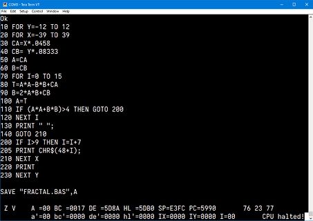
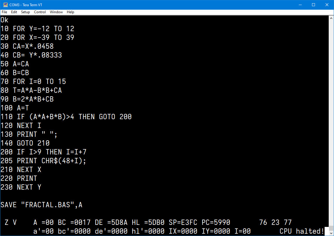
Ok
10 FOR Y=-12 TO 12
20 FOR X=-39 TO 39
30 CA=X*.0458
40 CB=Y*.08333
50 A=CA
60 B=CB
70 FOR I=0 TO 15
80 T=A*A-B*B+CA
90 B=2*A*B+CB
100 A=T
110 IF (A*A+B*B)>4 THEN GOTO 200
120 NEXT I
130 PRINT " ";
140 GOTO 210
200 IF I>9 THEN I=I+7
205 PRINT CHR$(48+I);
210 NEXT X
220 PRINT
230 NEXT Y
SAVE "FRACTAL.BAS",A
Z V A=00 BC =0017 DE=5D8A HL=5DB0 SP=E3FC PC=5990 76 23 77
a'=00 bc'=0000 de'=0000 hl'=0000 IX=0000 IY=0000 I=00 CPU halted!
and INPUT VSWRversus FREQUENCY 100 100 -20 90 90 -25 VDD12.5V VGG5V 80 80 -30 P =50mW ) Pout ) in W -70 70 % -35 (u ̸ η c Po ρ60 60 y d-40 e R η n s w S50 ̓ 50 i i-45 P V f o 2nd u u40 40 E r-50 t n t a u I30 30 o H O VDD12.5V T -55 20 VGG5V 20 -60 3rd Pin50mW 10 Л 10 -65 in 0 0 -70 130 140 150 160 170
the data direction (writing to I2C device) in i2c_start() */ #define I2C_WRITE 0 /** defines the base address of the EA eDIPTFT70-A */ #define DISPLAY_I2C_ADDR 0xDE #define DISPLAY_I2C_DC2 0x12 #define DISPLAY_I2C_ACK 0x06 #define DISPLAY_I2C_NACK 0x15 void i2c_init(void); unsigned char i2c_startDisplay
Allpage 38 of 90ved Easy GPRS User Guide 80000ST10028 r9, 2010-10-04 3.2.1.8 Sending and receiving base64 encoded data Through new #BASE64 command is possible to enable base64 encoding/decoding of data sent/received on a socket. The command syntax is: AT#BASE64=<connId>,<enc>,<dec> where <enc> and <dec

 Bild
Bild
 Bild
Bild