-
PDF
Spielfeld-Mini-200.pdf
LED - Spielbrett mit WS2812B 144 LED /m Lageplan der Bauteile 32 33 34 35 36 + + 31 + 7 6 0 3 11 5 3 + 8 + 8 3 12 + 29 2 + 9 + 28 4 + e 7 40 S Zi 4 27 p 3 6 1 l er 2 5 + 1 1 iel r2 Sp 10 2 8 9 6 + 4 3 + + 7 + + 4 5 2 1 25 26
in „Gefräste Platine rationell mit LED 's bestücken“ · Platinen ·
-
 Bild
Bild
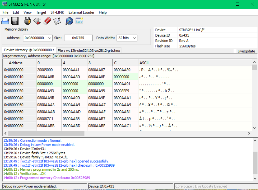
STM32 ST-LINK Utility Speicheranzeige
Address: 0x08000000 Size: 0xD755 Data Width: 32 bits Device Memory @ 0x08000000 File: [wc12h-stm32f103-ws2812-grb.hex] 0x08000000 20050000 0800AA41 0800AA87 0800AA89 0x08000100 0800AA8B 0800AA8D 0800AA8F 00000000 0x08000200 00000000 00000000 00000000 0800AA91 0x08000300 0800AA93 00000000 08008EF9 0x08000400
in „WordClock mit WS2812“ · Projekte & Code · · Screenshots
-
 Bild
Bild
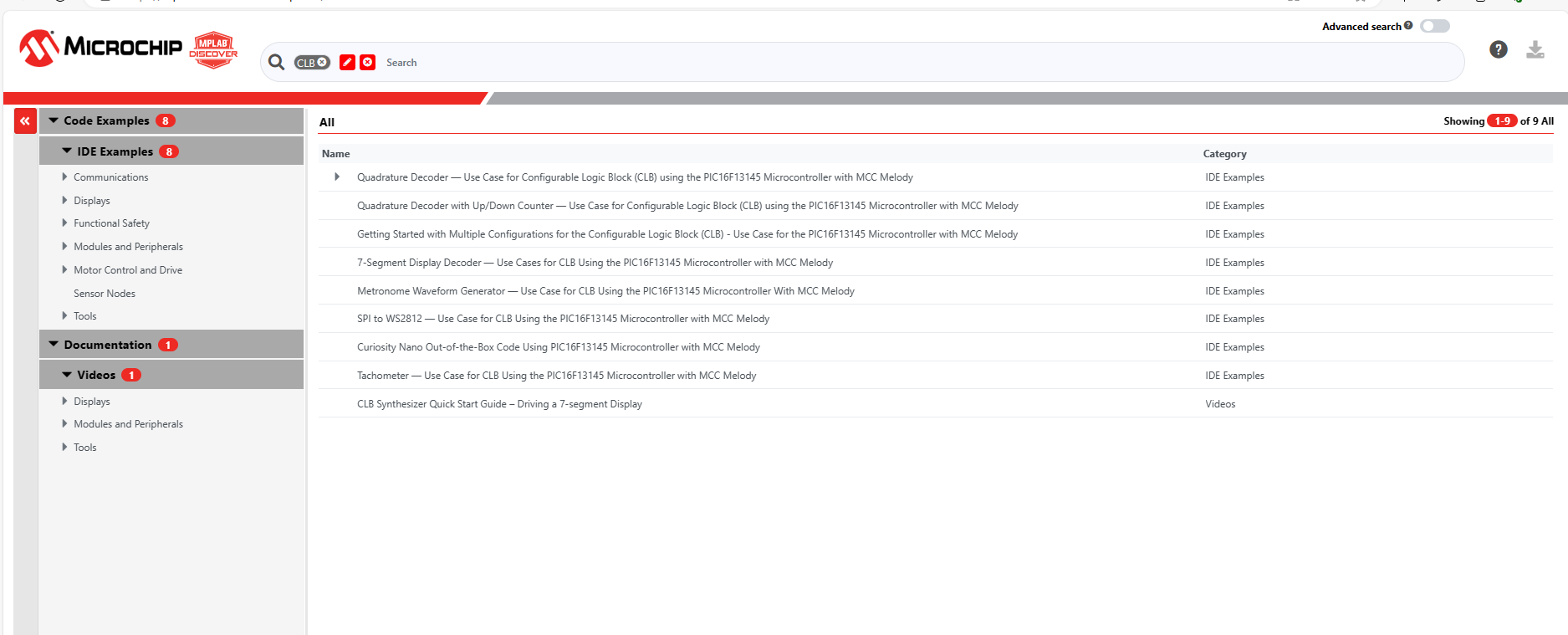
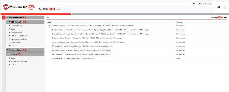
Liste von Microchip Code Examples
Curiosity Nano Out-of-the-Box Code Using PIC16F13145 Microcontroller with MCC Melody IDE Examples SPI to WS2812 - Use Case for CLB Using the PIC16F13145 Microcontroller with MCC Melody IDE Examples Tachometer - Use Case for CLB Using the PIC16F13145 Microcontroller with MCC Melody IDE Examples CLB Synthesizer
in „Microchip CLB - Messung des Propagationsdelays und Ausblick“ · Mikrocontroller und Digitale Elektronik · · Screenshots
-
Datei
main.c
util/delay.h> #include <avr/interrupt.h> #include <avr/io.h> #include <avr/sleep.h> #include "light_ws2812.h" #include "config.h" #include "debounce.h" #include "led_modes.h" volatile uint8_t sys_tick = 0u; ISR( TIMER0_OVF_vect ) // every 10ms { TCNT0 = (uint8_t)(int16_t)-(F_CPU / 1024 * 10e-3 + 0.5); /
in „Code zu groß für AtTiny45“ · Mikrocontroller und Digitale Elektronik ·
-
 Bild
Bild
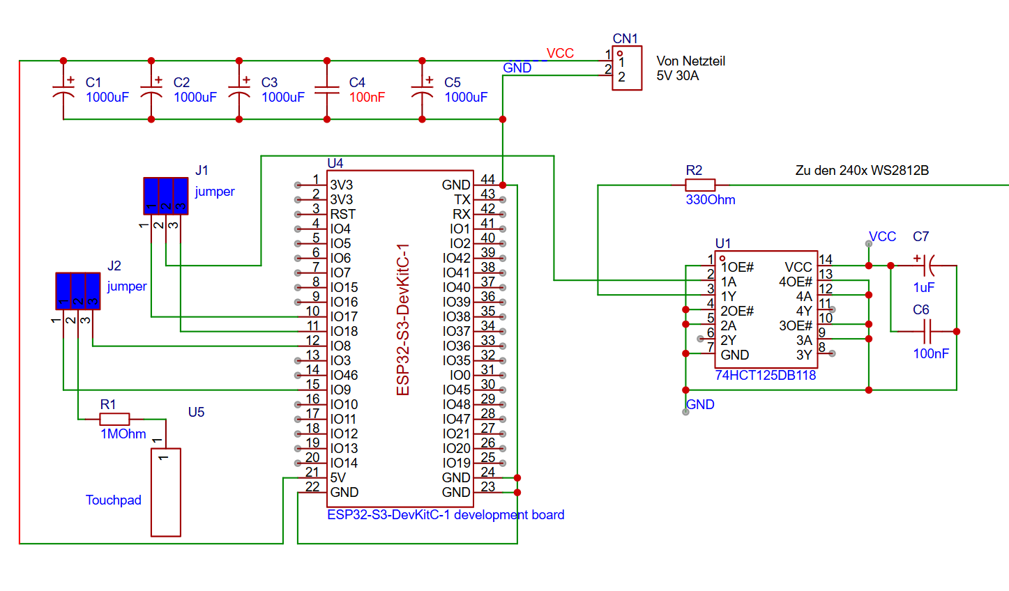
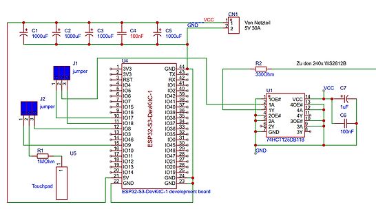
Schaltplan ESP32-S3-DevKitC-1 mit Peripherie
1000uF C3 1000uF C4 100nF C5 1000uF CN1 1 2 VCC GND 5V 30A J1 jumper J2 jumper R2 330Ohm Zu den 240x WS2812B U4 ESP32-S3-DevKitC-1 1 3V3 2 3V3 3 RST 4 IO4 5 IO5 6 IO6 7 IO7 8 IO5 9 IO6 10 IO7 11 IO8 12 IO8 13 IO4 14 IO5 15 IO9 16 IO10 17 IO11 18 IO12 19 IO13 20 IO14 21 5V 22 GND 44 GND 43 TX 42 RX 41 IO
in „ESP32 und 240Stück WS2812B“ · Mikrocontroller und Digitale Elektronik · · Schaltpläne
-
Datei
main.c
avr/sleep.h> #include "includes/config.h" #include "includes/debounce.h" #include "includes/light_ws2812.h" #include "includes/led_modes.h" volatile uint8_t sys_tick = 0u; ISR( TIMER0_OVF_vect ) // every 10ms { TCNT0 = (uint8_t)(int16_t)-(F_CPU / 1024 * 10e-3 + 0.5); // preload for 10ms sys_tick = 1u;
in „Code zu groß für AtTiny45“ · Mikrocontroller und Digitale Elektronik ·
-
PDF
Schaltplan.pdf
1 2 3 4 5 6 D D VCC R4 1 C5 LED1 Messfläche 100pF C L1 C 100uH WS-2812-5 D t D N o D i VCC VCC G D V D VCC C4 1 2 3 4 R7 100nF GND +C1 D1 + C2 10K T1 2200uF 1N4007 100uF GNDVCC GND R5 IRLR8743PbF D2 R2 GND 4V7 100 4K7 IC1 GND GND R3 1 30 100 GND BT1 2 D1/Tx Vin 29 VCC
-
Datei
KnightRider.ino
/* a LED driver, knight rider style drives a string of intelligent LEDs (WS2812B) speed setting via voltage on analog input */ #include <Adafruit_NeoPixel.h> #define LED_CNT 30 #define LED_PIN 22 #define POTI_PIN A0 Adafruit_NeoPixel pixels(LED_CNT, LED_PIN, NEO_GRB + NEO_KHZ800
in „LED-Lauflicht im Knight Rider Style“ · Projekte & Code ·
-
PDF
Schematic_STM32L05__HSN-TTN_Mini_Node_LoRa_v1.2_2021-02-27.pdf
4 3 3 3 SCL 3 OS GND 8 NEOPIX VCC VEXTOUT D HDR-M-2.54_1x1 4 4 4 SDA R7 GND D 1 10K LED1 GND VCC WS2812B R470 1 4 2 VDD DIN 3 Neopix DOUT VSS GND GND VCC P1 STLINK connector 1 VCC 2 GND 3 SWCLK 4 SWDIO E 5 VCC-T E 6 RSTn C5 C6 100nF 10uF S S D C A L C4 100nF R10 R9 100k 100k JP1 U1 GND PINHD-1X12-CB
-
Datei
strandtest.ino
pixel type flags, add together as needed: // NEO_KHZ800 800 KHz bitstream (most NeoPixel products w/WS2812 LEDs) // NEO_KHZ400 400 KHz (classic 'v1' (not v2) FLORA pixels, WS2811 drivers) // NEO_GRB Pixels are wired for GRB bitstream (most NeoPixel products) // NEO_RGB Pixels are wired for RGB bitstream
in „Auswahl zweier Arduino Sketches“ · Mikrocontroller und Digitale Elektronik ·
-
Datei
led_modes.c
/* * led_modes.c * * Created: 05.05.2016 23:25:26 * Author: Hannes */ #include "includes/light_ws2812.h" #include <math.h> #include <stdlib.h> #define MAX 255 #define BASE 10 #define RESOLUTION 50 //number of steps to increment the brightness value struct cRGB *COLORS[14]; volatile struct cRGB LED_COLOR_old
in „Code zu groß für AtTiny45“ · Mikrocontroller und Digitale Elektronik ·
-
PDF
Schematic_Atmega_1284p_Mini_Lora_2021-11-18.pdf
TOSC1/PCINT22) 24 PC6 LED1 HDR-M-2.54_1x1 GND PC2 22 PC2(PCINT18/TCK) PC5(TDI/PCINT21)23 PC5 VCC WS2812B-B 1 VEXT PC3(PCINT19/TMS) PC4(TDO/PCINT20) PC4 1 VDD DIN 4 2 DOUT VSS 3 NEO GND J2 HDR-M-2.54_1x4 ARDUINO LED 1 PB1 19-217/BHC-ZL1M2RY/3T PB2 2 PB3 3 PB4 4 LED 1K J1 GND R4 HDR-M-2.54_1x6 D Pullups
in „Hilfe bei Schaltplan 1284p, Mosfet usw, MCU neustart“ · Mikrocontroller und Digitale Elektronik ·
-
Datei
usart.c
buffer start Address. } GPIOR0 |= (1<<USART_NEW_BYTE); //Set FLAG for action in Mainloop }//end WS2812_LEDCount_RX_Vect //USART TX UDR empty, write bytes from buffer till buffer is empty and disable itself, also maintain the TX_read pointer ISR(USART_UDRE_vect){ if( usart_tx_read == usart_tx_write )
in „Pointer Vergleich mit Konstante“ · Mikrocontroller und Digitale Elektronik ·
-
Datei
Liste.txt
Unbekannt 75x 3mm Rot LED 75 Stück unkannt 34x SMD LED Rot Unbekannt 35x Rot Gewinkelt Unbekannt 40x WS2812B RGB Intelligent control LED integrated light source (3,5-5 Volt) 1 Unbekannte Platine 4535670 60341/ Rafi lage 2 540 553634 7 Sekment Anzeigen 24x LTS2301e Unbekannt 10x7 mm ROT 10 Rot 12x17 mm Unbekannt
-
Datei
Neues_Textdokument__2_.txt
to WordClock Logger! ---------------------------- Version: 2.8.4 rtc is online eeprom is online ws2812: external pullup detected eeprom is online current eeprom version: 0x00020800 reading ir codes from eeprom DFPLAYER LOGGER ESP8266 LOGGER read rtc: Th 2018-02-15 10:35:48 esp8266 now up (- setup UDP
-
PDF
Elektronik_Sortimente.pdf
1-2x LED-Streifen: WS2801B (Achtung: Unterschiedliche Anzahl LEDs pro Meter) 1-2x LED-Streifen: WS2812B (Achtung: Unterschiedliche Anzahl LEDs pro Meter) 10x Siebensegment-Anzeige * alle Elemente in Through the Hole und in SMD Bauweise (0805, 0603) Sicherungen Sortiment 5x20mm, flink, 0,16A … 6,3A (
in „Einkaufsliste für die Einrichtung eines Elektronik-Labors“ · Mikrocontroller und Digitale Elektronik ·
-
Datei
riennevaplus.vhd
30 ns Taktperiode für einen 33 MHz Takt constant cCKPERIOD_NS : integer := 30; -- die Zeiten für WS2812B constant cRESET_NS : integer := 50000; constant cT0H_NS : integer := 400; constant cT0L_NS : integer := 850; constant cT1H_NS : integer := 800; constant cT1L_NS : integer := 450; -- die entsprechende
-
Datei
main.c
setzen ende // LED Daten schreiben for (ledschleife=0; ledschleife < LEDANZAHL; ledschleife++) { ws2812_setleds(led,ledschleife+1); } // LED Ende // Temperatur lesen if (sekunde%10) { if (readtemp == 0) { ow_reset(); ow_wr_byte(0xCC); //Skip ROM ow_wr_byte(0x44); // Start Conversion readtemp = 1; } else
in „arrays und struct in funktionen“ · Mikrocontroller und Digitale Elektronik ·
-
PDF
howto_-tasmota-sml.pdf
DZ #undef USE_SONOFF_IFAN #undef USE_BUZZER #undef USE_ARILUX_RF #undef USE_DEEPSLEEP #undef USE_WS2812 #undef USE_MY92X1 #undef USE_SM16716 #undef USE_SM2135 #undef USE_SONOFF_L1 #undef USE_COUNTER #undef USE_DS18x20 #undef USE_SHT #undef USE_HTU #undef USE_BH1750 #undef USE_SHT3X #undef USE_LM75AD
in „Wärmezähler über optische M-Bus-Schnittstelle auslesen“ · Haus & Smart Home ·
-
Datei
display.c
#define led_set_led apa102_set_led #define led_set_all_leds apa102_set_all_leds #else #include "ws2812.h" #define LED_RGB WS2812_RGB #define led_init ws2812_init #define led_refresh ws2812_refresh #define led_set_led ws2812_set_led #define led_set_all_leds ws2812_set_all_leds #endif #include "eeprom.h
-
PDF
PicoMite_User_Manual.pdf
(green), RGB(blue), RGB(Yellow), rgb(cyan)) SETPIN GP5, DOUT BITBANG WS2812 O, GP5, 5, b%() will output the specified colours to an array of five WS2812 LEDs daisy chained off pin GP5. It is possible that a WS2812 will not work reliably with the 3.3V output from the PicoMite. In this case there are a number of solutions: Use the WS2812B which will work with a 3.3V supply and inputs. Use a level shifter to drive the WS2812. Use a single WS2812 powered from 3.3V as a first stage to buffer the input of the first "real" LED in the
in „allgemeine PicoMite Anfängerfragen“ · Mikrocontroller und Digitale Elektronik ·
-
PDF
PicoMite_User_Manual_4_.pdf
(green), RGB(blue), RGB(Yellow), rgb(cyan)) SETPIN GP5, DOUT BITBANG WS2812 O, GP5, 5, b%() will output the specified colours to an array of five WS2812 LEDs daisy chained off pin GP5. It is possible that a WS2812 will not work reliably with the 3.3V output from the PicoMite. In this case there are a number of solutions: Use the WS2812B which will work with a 3.3V supply and inputs. Use a level shifter to drive the WS2812. Use a single WS2812 powered from 3.3V as a first stage to buffer the input of the first "real" LED in the
in „Qual der Wahl - Sensoren Auswertung auf Display ("Analog")“ · Mikrocontroller und Digitale Elektronik ·
-
Datei
Liste.txt
---------------------------------------------------- +3x Grün Schaltschrank Warnleuchte 230V 40x WS2812B RGB Intelligent control LED integrated light source (3,5-5 Volt) 1 Unbekannte Platine 4535670 60341/ Rafi lage 2 540 553634 ------------------------------------------------------------------------
-
Datei
main.c
brightness * (width - fwLed) / width); } FastLED.show(); } } int main(void) { init(); FastLED.addLeds<WS2812B, DATA_PIN, GRB>(leds, NUM_LEDS); ledsClear(); Serial.begin(115200); volatile unsigned long data[6]; enum dataIndex { mode, hue, saturation, brightness, duration, width }; data[mode] = 6; data[hue]
in „C++: struct an class übergeben“ · Mikrocontroller und Digitale Elektronik ·
-
Datei
code.c
//setup leds incl. fastled for (int i = 0; i < NUM_LEDS; i++) { strip[i] = 0; } FastLED.addLeds<WS2812B, STRIP_DATA_PIN, GRB>(leds, NUM_LEDS); resetAndBlack(); displayStrip(); // setup dcf DCF.Start(); setSyncInterval(60); //every hour setSyncProvider(getDCFTime); while (timeStatus() == timeNotSet)
in „Arduino hängt sich auf (Wordclock)“ · Mikrocontroller und Digitale Elektronik ·
-
PDF
Arduino_Cheat_Sheet_fuer_ESP32_V3c.pdf
RGB_LED if(server.hasArg("r") || server.hasArg("g") || server.hasArg("b")) ADC2_0 TOUCH11 GPIO11 WS2812 GPIO47 { uint16_t red, green, blue; String Temp; byte TouchValue = touchRead(T0); // T0-T9 R D D Temp = server.arg("r"); // Server sendet Strings ADC2_1 TOUCH12 GPIO12 WT R GPIO21 red = Temp.toInt(
in „ESP32 Arduino Cheat Sheet (aktuell für BSP3.x)“ · Mikrocontroller und Digitale Elektronik ·
-
PDF
Arduino_Cheat_Sheet_fuer_ESP32_V3d.pdf
RGB_LED if(server.hasArg("r") || server.hasArg("g") || server.hasArg("b")) ADC2_0 TOUCH11 GPIO11 WS2812 GPIO47 { uint16_t red, green, blue; String Temp; byte TouchValue = touchRead(T0); // T0-T9 R D D Temp = server.arg("r"); // Server sendet Strings ADC2_1 TOUCH12 GPIO12 WT R GPIO21 red = Temp.toInt(
in „ESP32 Arduino Cheat Sheet (aktuell für BSP3.x)“ · Mikrocontroller und Digitale Elektronik ·
-
PDF
Arduino_Cheat_Sheet_fuer_ESP32_V3e.pdf
RGB_LED if(server.hasArg("r") || server.hasArg("g") || server.hasArg("b")) ADC2_0 TOUCH11 GPIO11 WS2812 GPIO47 { uint16_t red, green, blue; String Temp; byte TouchValue = touchRead(T0); // T0-T9 R D D Temp = server.arg("r"); // Server sendet Strings ADC2_1 TOUCH12 GPIO12 WT R GPIO21 red = Temp.toInt(
in „ESP32 Arduino Cheat Sheet (aktuell für BSP3.x)“ · Mikrocontroller und Digitale Elektronik ·
-
PDF
Arduino_Cheat_Sheet_fuer_ESP32_V3e_PDF_A.pdf
RGB_LED if(server.hasArg("r") || server.hasArg("g") || server.hasArg("b")) ADC2_0 TOUCH11 GPIO11 WS2812 GPIO47 { uint16_t red, green, blue; String Temp; byte TouchValue = touchRead(T0); // T0-T9 R D D Temp = server.arg("r"); // Server sendet Strings ADC2_1 TOUCH12 GPIO12 WT R GPIO21 red = Temp.toInt(
in „ESP32 Arduino Cheat Sheet (aktuell für BSP3.x)“ · Mikrocontroller und Digitale Elektronik ·
-
PDF
ATtiny1614_RPi5_PowerButton_IR_WS2812_Oled_3.3VZener_v0.01.pdf
ATtiny1614_RPi5_PowerButton_IR_WS2812_Oled_3.3VZener_v0.01.pdf
in „RPi 5 externer Ein/Aus Taster mit Led als Statusanzeige [Schaltplan Hilfe]“ · Mikrocontroller und Digitale Elektronik ·
-
PDF
ATtiny412_RPi5_PowerButton_IR_WS2812_Oled_3.3VZener_v0.01.pdf
ATtiny412_RPi5_PowerButton_IR_WS2812_Oled_3.3VZener_v0.01.pdf
in „RPi 5 externer Ein/Aus Taster mit Led als Statusanzeige [Schaltplan Hilfe]“ · Mikrocontroller und Digitale Elektronik ·
-
Datei
dmx-demux3.ino
zero_crosss_int, RISING); Timer1.initialize(10); Timer1.attachInterrupt(timerIsr); FastLED.addLeds<WS2812, DATA_PIN, RGB>(leds, NUM_LEDS); } void loop(void) { currentMillis = millis(); if(currentMillis < currentMilliswatch){ // Watchdog to Reset all Millis when Millis buffer restart after 50 days previousMillisS
in „Probem mit Arduino DMXSerial und WS2812 / Triac Steuerung“ · Mikrocontroller und Digitale Elektronik ·
-
Datei
wordclock_esp.txt
= 50; Grün = 50; Blau = 50 => ergibt einen weißen Farbton. //Tipp: Der blaue Anteil muss bei den WS2812B-LED's etwas reduziert werden, da dieser dominanter ausfällt. //Helligkeit der LED's kann mit Werten zwischen 0 - 255 eingestellt werden. //Beispiel 1: Rot = 255; Grün = 255; Blau = 255 => weißer Farbton
in „ESP8266 startet nicht“ · Mikrocontroller und Digitale Elektronik ·
-
Datei
Configuration.h
and LEDs // //#define OVERLORD_OLED // // FYSETC OLED 2.42" 128×64 FULL GRAPHICS CONTROLLER with WS2812 RGB // Where to find : https://www.aliexpress.com/item/4000345255731.html //#define FYSETC_242_OLED_12864 // Uses the SSD1309 controller //==========================================================
in „Ender3 Z-Achse fährt mit Marlin nur nach oben“ · Mechanik, Gehäuse, Werkzeug ·
-
Datei
Configuration.h
and LEDs // //#define OVERLORD_OLED // // FYSETC OLED 2.42" 128×64 Full Graphics Controller with WS2812 RGB // Where to find : https://www.aliexpress.com/item/4000345255731.html //#define FYSETC_242_OLED_12864 // Uses the SSD1309 controller // // K.3D SSD1309 OLED 2.42" 128×64 Full Graphics Controller
in „Custom 3D-Drucker zu ausgebuchtete Ecken“ · Mechanik, Gehäuse, Werkzeug ·