26262 and IEC 61508 functional safety standards, use the AVR CPU with a hardware multiplier running at clock speeds up to 20 MHz. They include 32/64 KB of Flash, 4/8 KB of SRAM, and 256 bytes of EEPROM. The microcontrollers are available in 20-, 28-, 32- and 48-pin packages. The family uses our latest
int bestn = -1; int bestpre = -1; int besterr = 0; int errval; for (n = 2; n <= 64; n++) { //Start at 2: we need to be able to set h/l so we have at least one high and one low pulse. //Effectively, this does pre=round((fapb/n)/hz). pre = ((fapb / n) + (hz / 2)) / hz; if (pre <= 0) { pre = 1; } if (pre
5 mA to -1 A PO≤ 15 W -19 -20 -21 V VI= -24 to -35 V ∆VO(*) Line Regulation VI= -23 to -35 V TJ= 25°C 400 mV VI= -26 to -32 V TJ= 25°C 200 ∆VO(*) Load Regulation O = 5 mA to 1.5 A TJ= 25°C 400 mV I = 250 to 750 mA T = 25°C 200 O J d Quiescent
Ich habe hier grade spi Takt 25MHz. LA1010 wäre dann zu langsam? Andereseits konnte ich mit dem 24MHz Analyser 10MHz spi lesen.
/www.saleae.com/logic16 "Money Quote:" > Logic16 can sample 2 channels 100MHz, > 4 channels at 50MHz, > 8 channels at 25MHz or > all 16 channels at 12.5MHz Es gibt auch einen Open-Source-DIY-Logikanalysator: http://dangerousprototypes.com/docs/Open_Bench_Logic_Sniffer Der ist allerdings
eine Variante geben wird, die den für den Anschluss an den Raspberry Pi notwendigen Hat mitbringt: [c] The entry-level 256GB drive is priced at $30 on its own, or $40 as a kit; its 512GB big brother is priced at $45 on its own, or $55 as a kit. Both densities offer minimum 4KB random read and write performance of 40k IOPS and 70k IOPS respectively. The 256GB SSD and SSD Kit are available to buy today, while the 512GB variants are available to pre-order now for shipping by the end of November. [/c] ### Raspberry Pi AI HAT+ - neue Variante des AI-Beschleunigers
Dieser Prozessor von Anfang 23 hat 10 TOPS. Der ansonsten identische Nachfolger Hawk Point von Anfang 24 hat 16 TOPS. Erst der brandneue Strix Point hat bis zu 50 TOPS, passt also zum Copilot. AMDs NPU wird überhaupt erst von Win 24H2 unterstützt. Ich habe bisher nicht herauszufinden können, was ich
mein Arbeitgeber spendiert und einem halben Kellerraum voll von Computerschrott): Laptop mit USB-C Thunderbold an einem USB-C Hub-Monitor Im der Bastelbude ein No-Name Mini-PC. Vorher stand da ein Tower mit vielen RS232 Schnittstellen.
group-mcus-outstanding-power-efficiency-advanced-touch-functions Über die „eigentlichen“ technischen Parameter vermeldet Renesas folgendes: [c] Key Features of the RX261/RX260 Group MCUs (* available on RX261 only) • 64 MHz RXv3 core (355CoreMark) • Memory: 256KB/384KB/512KB code flash, 8KB data flash, 128KB SRAM • Low power
sich nun folgende Passage, die die Einschätzung von Renesas im Bezug auf die iO Link zusammenfasst: [c] IO-Link Market Projected to Grow at Over 20 Percent Annually Through 2028 [/c] Aus dieser positiven und Wachstums-freudigen Einschätzung lässt sich die Auslieferung von zwei neuen Produkten ableiten
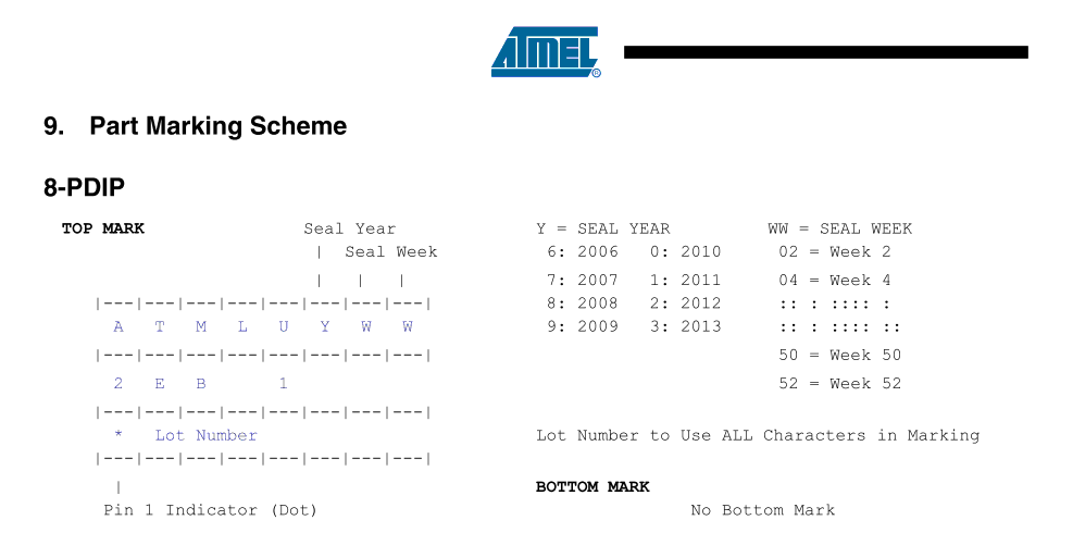
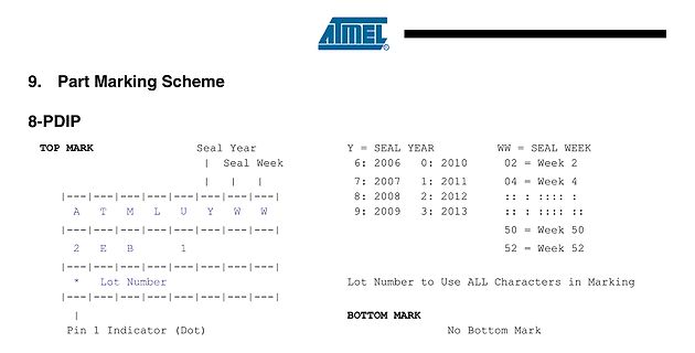
9. Part Marking Scheme
8-PDIP
TOP MARK
Seal Year
Y = SEAL YEAR WW = SEAL WEEK
| Seal Week
6: 2006 0: 2010 02 = Week 2
7: 2007 1: 2011 04 = Week 4
8: 2008 2: 2012 :: : : :
9: 2009 3: 2013 :: : : : ::
50 = Week 50
52 = Week 52
Lot Number to Use ALL Characters in Marking
BOTTOM MARK
No Bottom Mark
tried to follow the example from this forum and I don't know what I do wrong, I can't read the memory at all. I use stm32 cube ide, and when I tried to read memory address 0xC0000000, it shows '????????', not a random hex, even when I tried to write some data, nothing changed. This is my first time
Electrical Characteristics”, page 23. 5. Parts are guaranteed to operate down to 0Hz. 2000 Jan 20 24 Philips Semiconductors Product specification 80C51 8-bit microcontroller family 4K/128 OTP/ROM/ROMless, low voltage (2.7V–5.5V), 80C51/87C51/80C31 low power, high speed (33 MHz) EXPLANATION OF THE AC
0000 ??ERAM_SIZE NUMBER 0000 ??FDATA_SIZE NUMBER 0000 ??RAM_SIZE NUMBER 0100 ??VERSION NUMBER 0120 ??_AT89C2051_ NUMBER 001B ??_AT89C4051_ NUMBER 001C ??_AT89C51ED2_ NUMBER 0026 ??_AT89C51IC2_ NUMBER 0024 ??_AT89C51ID2_ NUMBER 0025 ??_AT89C51RB2_ NUMBER 0021 ??_AT89C51RC2_ NUMBER 0022 ??_AT89C51RC_ NUMBER 0020 ??_AT89C51RD2_ NUMBER 0023 ??_AT89C51_ NUMBER 001D ??_AT89C52_ NUMBER 001E ??_AT89C55WD_ NUMBER 001F ??_AT89LP2052_ NUMBER 0001 ??_AT89LP213_ NUMBER 0003 ??_AT89LP214_ NUMBER 0004 ??_AT89LP216_ NUMBER 0005
ANS 1523-0005 Lithium-Thionylchlorid Batterie ER26500 / C Maße Ø 26,5 mm Höhe 50 mm 3,6Volt ??
interface. https://www.eevblog.com/forum/repair/quick-repair-project-marconi-2024/?all da wird ein AT28C256 erwähnt, kann aber sein, dass es dabei um den 2025 geht. Und ein Level2-Passwort, wie man es herausfindet (2025?) Hier ein Foto der Rückseite, aber ohne Batteriehalterung: https://www.rigpix.com
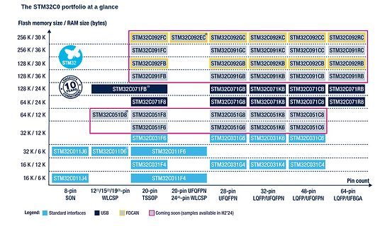
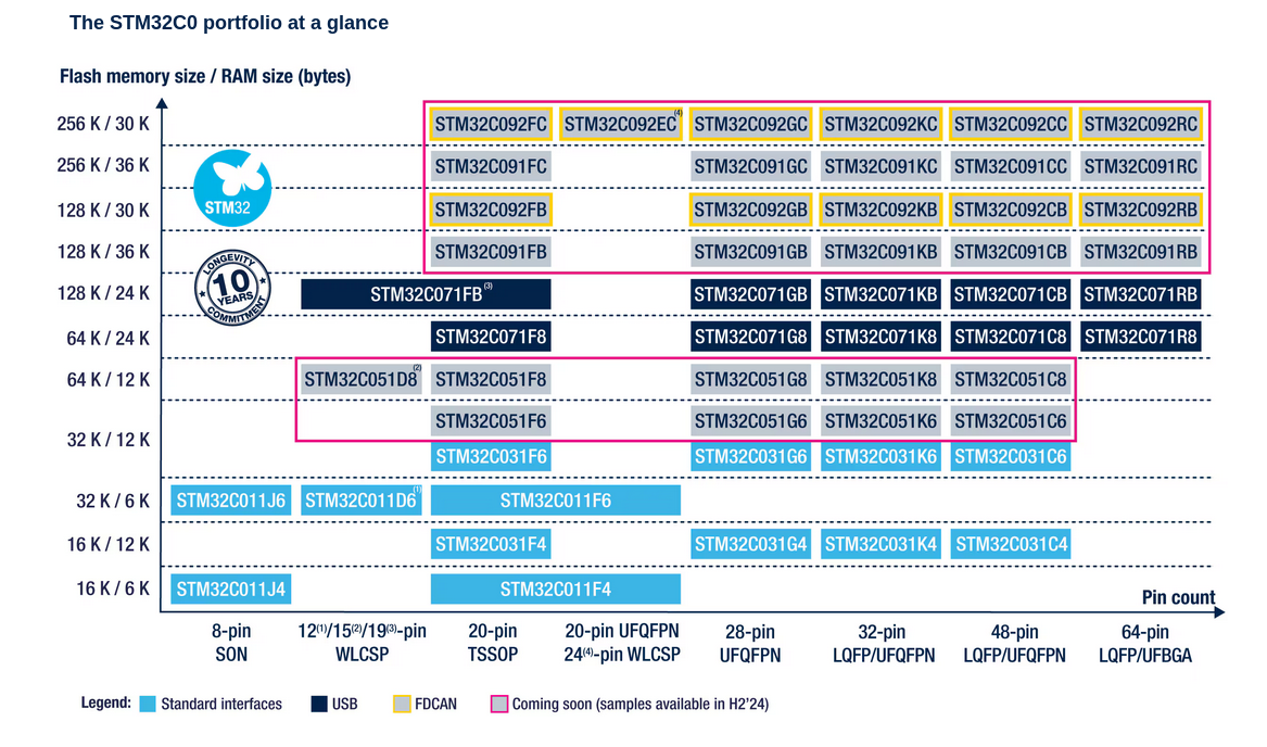
The STM32C0 portfolio at a glance
Flash memory size / RAM size (bytes)
256 K / 30 K
128 K / 30 K
128 K / 36 K
128 K / 24 K
64 K / 24 K
64 K / 12 K
32 K / 12 K
32 K / 6 K
16 K / 12 K
16 K / 6 K
STM32C092FC, STM32C092EC, STM32C092GC, STM32C092KC, STM32C092CC, STM32C092RC, STM32C091FC, STM32C091GC, STM32C091KC, STM32C091CC, STM32C091RC, STM32C092FB, STM32C092GB, STM32C092KB, STM32C092CB, STM32C092RB, STM32C091FB, STM32C091GB
******* ; ; file register declarations: uses only registers in bank0 ; bank 0 file registers begin at 0x0c in the 16F84 ; and at 0x20 in the 16F628 ; ;******************************************************************* cblock RAMStart ; ; Floating Point Stack and other locations used by FP.TXT ; ; FP
than 40-Year Data Retention 8 1 SO8 (MN) 150 mil width Table 1. Product List Reference Part Number M24C64 M24C64 M24C64-W TSSOP8 (DW) M24C64-R 169 mil width M24C32 M24C32 M24C32-W M24C32-R UFDFPN8 (MB) 2x3mm² (MLP) January 2005 131 AVR145 harman/kardon M24C64, M24C32 SUMMARY DESCRIPTION 2 These I C-compatible
eines i286 > passen. Wenn es dafür vorgesehen wäre, wäre es ein reichlich geniales > Stück HW. Ein AT mit 12 MHz würde damit einen gewaltigen Sprung nach > vorne machen. Sowas gab es tatsächlich mal - die c't hat (damals, als sie sich noch mit Hardware beschäftigte) ein entsprechendes Selbstbauprojekt
en.wikipedia.org/wiki/Cyrix_Cx486SLC Oder der 486SLC2, der intern mit dem doppelten Takt lief. Im 12-MHz-AT wären das immerhin atemberaubende 24 MHz gewesen ... Das wesentliche Problem aber war damit nicht lösbar: zu wenig Speicher. Selbst echte 386er waren nur sehr selten dafür vorgesehen, mit mehr als
− °C A G001 A G002 Figure 1. Figure 2. 6 Submit Documentation Feedback PCM1801 www.ti.com SBAS131C–OCTOBER 2000–REVISED JULY 2007 TYPICAL PERFORMANCE CURVES (continued) All specifications at A = 25°C, V DD
Resultate. Ich habe auch an einen 50pol. Universal-Tester gedacht. Hauptsächlich möchte ich erst mal USB-C und HDMI-Kabel testen. Geprüft werden soll natürlich primär auf Durchgang von einem Kabelende zum anderen. Als zweites aber auch auf Schlüsse zwischen den Adern selbst. Letzteres würde einseitig reichen
Ich habe mal nen Tester für bis zu 40 polige Flachkabel gebaut. Verwendet wurden 3 AT89C51 mit je 32 IO-Pins. Über die UART wurden sie kaskadiert. Alle 3 bekamen die gleiche Firmware. RXD des ersten wurde auf low gelegt, damit er weiß, daß er mit Testen anfangen soll. Es werden Muster
fertigen lassen. Unterschiede zur Originalplatine sind nur der Speicherchip. Ich verwende einen AS6C62256 (Datasheet:https://www.mouser.at/datasheet/2/12/AS6C62256_23_March_2016_rev1_2-1288423.pdf) statt des BS62LV256PIP55. Nach dem Einschalten scheint die Platine auch zu funktionieren, aber beim
J-K Flip Flops etc). Ein Tüftler hat dann dieses Originaldesign vereinfacht und getuned auf bis zu 24MHz, indem der die modernen Bausteine W65C02S und W65C22 von Western Design Center, schnelle Gatter (74Fxx) und schnelles RAM (55ns bzw. 15ns bei der 24MHz Variante) verbaute. Ich bin über Umwegen an
bezeichnete RISC/V-Kerne befinden. Der Betrieb der beiden Kerne ist dabei allerdings Entweder-Oder: [c] RP2350 includes a pair of open-hardware Hazard3 RISC-V cores which can be substituted at boot time for the Cortex-M33 cores. Our boot ROM can even auto-detect the architecture for which a second-stage
assignable to security domains • Hardware mitigations for fault injection attacks • Hardware SHA-256 accelerator 2 × UART 2 × SPI controllers 2 × I2C controllers 24 × PWM channels 4/8 x ADC channels 1 × USB 1.1 controller and PHY, with host and device support 12 × PIO state machines Software-compatible
Beckenwasser und Raumtemperatur sowie der Nutzung des Schwimmbades ab. Raumtemperatur Wassertemperatur 20 °C 24 °C 28 °C 2 2 2 23 °C 90 W/m 165 W/m 265 W/m 25 °C 65 W/m 2 140 W/m 2 240 W/m 2 28 °C 2 2 2 20 W/m 100 W/m 195 W/m Subject to change and error 28/327 Version 11/2021 Tab. 1.6: Anhaltswerte für den
zero, i.e. the first and the second integrals on the right of (3.23) disappear, it results in N −∇ (c∇Φ) − f dΩ+ N (c∇Φ) n − h dΓ = 0. (3.24) Ω ΓN This is the sum of two terms, the first one is the inner product of the partial differential equation and the weighting function, the second term is the Neumann
at the protocol level. The SMBus clock is defined from 10 kHz to 100 kHz while I C can be 0 Hz to 100 kHz, 0 Hz to 400 kHz, 0 Hz to 1 MHz and 2 0 Hz to 3.4 MHz, depending on the mode. This means that an
brauche (z.B. von kanda.com). Ich habe ja schon mal serielle EEPROMs (z.B: 24C0x) programmiert. Nun ist das AT17LV… ja wohl auch ein serielles EEPROM. Also ist bei mir die Frage aufgetaucht was denn die wesentlichen Unterschiede zwischen z.B: einem 24C0x und einem AT17LV… sind
Laut Doku zum AT17LV256 ist das I2C und vergleichbar mit der Art wie z.B. der 24LC256 gelesen und geschrieben wird. Allerdings gibt es ein paar Besonderheiten: - Man muss sich um den richtigen Pegel an RESET,
trade-offs resistance R .ININ and R IN relationships shown in the table below: V IN 5V 6V 9V 12V 15V 18V 24V R IN 33 100R 470R 1K 1.5K 2K 3K SK6812RGBP8 data output port of the DOUT load equivalent capacitance C , L every data transfer cycle DOUT must to C L charging, the charging current transient about 40
voltage (V = 0) 600 V DS GS V Gate-source voltage ± 30 V GS (1) ID Drain current (continuous) Ct T = 25 °C 6 6 A ID Drain current (continuous) Ct T = 100 °C 3.8 3.8 (1) A IDM (2) Drain current (pulsed) 24 24(1) A P Total dissipation at T = 25 °C 110 30 W TOT C Derating factor 0.88 0.24 W/°C V G-S ESD (HBM
voltage (V = 0) 600 V DS GS V Gate-source voltage ± 30 V GS (1) ID Drain current (continuous) Ct T = 25 °C 6 6 A ID Drain current (continuous) Ct T = 100 °C 3.8 3.8 (1) A IDM (2) Drain current (pulsed) 24 24(1) A P Total dissipation at T = 25 °C 110 30 W TOT C Derating factor 0.88 0.24 W/°C V G-S ESD (HBM
war dann bei Alteras Quartus auch wiederzuerkennen. Der dort verwendete FPGA, ein XC3S400A-4FTG256C, ist aber mit einem 400000 Gatteraequivalent, *wesentlich* groesser als der Renesaszwerg. Und das wird dir vermutlich schon beim ersten interessanten Projekt das du umsetzen moechtest, auf die Fuesse
darf nicht mehr als 1 mA fliessen. Da bist Du in die falsche Zeile gerutscht: Das ist "Current at Digital **Input** Pin".
SHT43 typical and maximal relative Figure 5. SHT45 typical and maximal relative humidity accuracy at 25 °C. humidity accuracy at 25 °C. 2.1.1 Relative Humidity Accuracy at the Extended Temperature Range The typical RH accuracy tolerances in the range of T = 0 °C … 80 °C are given in Figure 6, Figure
SHT43 typical and maximal relative Figure 5. SHT45 typical and maximal relative humidity accuracy at 25 °C. humidity accuracy at 25 °C. 2.1.1 Relative Humidity Accuracy at the Extended Temperature Range The typical RH accuracy tolerances in the range of T = 0 °C … 80 °C are given in Figure 6, Figure

 Bild
Bild
 Bild
Bild