voltage 0.8 VCC VCC V VIL Low-level input voltage GND 0.2 VCC V OH High-level output current VCC = 5 V at SOUT –1 mA OL Low-level output current VCC = 5 V at SOUT, XERR 1 mA OLC Constant output current OUT0 to OUT15 80 mA T Operating junction temperature –40 125 °C J TA Operating free-air temperature range
level at 0x003C Si4704/05-D50 and later, MULTIPATH_END_ which hi-cut reaches maxi- Si4706-D50, THRESHOLD mum band limiting. Default Si4730/31/34/35-D60 and value is 60. later, Si4732 0x1A06 FM_HICUT_ CUTOFF_
..1000 Ohm, evtl. auch mehr haben (betrifft LO-PegelbeimLesenvonDatenbzw. dem ACK-Bit). A2 = VSS I2C-Address Function 8 Bit 7 Bit $78 $3C Write Command $79 Read Status $7A Write Data $7B $3D Read Data A2 = VDD I2C-Address 8 Bit 7 BitFunction $7C Write Command $3E $7D Read Status $7E $3F Write Data $7F
HC595writePin(i, 1); osDelay(100); } } /* USER CODE END 5 */ } [/c]
wann aus Komfort- oder Geschwindigkeitsgründen das genaue Gegenteil angewandt werden darf – bei einem AT89C2051 oder AT89C51 kommt es auf jedes Byte an und dort muss man teilweise extrem sparen und oft auch zu Assembler greifen, weil auch der Flash relativ kurz ist, beim STM32 ist es Unsinn, krampfhaft
integral reverse G SM -260 (Body Diode) p-n junction diode. S V Diode Forward Voltage -1.6 V T = 25°C, I = -38A, V = 0V SD J S GS trr Reverse Recovery Time 89 130 ns T J 25°C, F = -38A Q Reverse Recovery Charge 230 350 nC di/dt = -100A/µs rr on Forward Turn-On Time Intrinsic turn-on time is negligible
Office/Distributors for availability and specifications. (3) The maximum allowable power dissipation at any ambient temperature is a function of the maximum junction temperature for operation (TJMAX = 125°C or 150°C), the junction-to-ambient thermal resistanceJAθ ), and the ambient temperatureA(T DMAX
tried to follow the example from this forum and I don't know what I do wrong, I can't read the memory at all. I use stm32 cube ide, and when I tried to read memory address 0xC0000000, it shows '????????', not a random hex, even when I tried to write some data, nothing changed. This is my first time
nur noch unter DOSBox laufen. Man braucht auch kein großes Entwicklungsboard mehr, ein AT89C51RB2 hat alles onboard. Mit Flip lädt man ein Programm über die UART in dessen Flash. https://www.digikey.de/de/products/detail/microchip-technology/AT89C51RB2-3CSUM/1245778 Die MCS51 lassen sich
NMOS waren. Noch zu DDR-Zeiten gab es CMOS-SRAM (U6516) im Bastlerladen. Damit habe ich dann später AT89C51 erweitert. Der 6516 hatte das nötige Adreßlatch ja schon eingebaut.
Response – µs Figure 16. MOSFET r DS(on) Vs. Junction Temperature 1400 150 1300 140 1200 130 A T = -40°C m120 -1100 A - n n110 TA= -40°C TA= 25°C e1000 T = 25°C e T A 125°C u 900 A u100 C C r 800 TA= 125°C c 90 u u 80 S 700 S i n 70 r 600 a D D 60 t 500 i t 400 a 50 - S 40 S 300 - I D 30 200 VIN = 6.5 V
loadable, enabled, up/down binary counter programmed into each LAB. (4) Operating conditions: A = 0° C to 70° CCCV= 5.0 V 5% for commercial use. TA= –40° C to 85° C, CC= 5.0 V 5% for industrial use. (5) These signals are measured at0.5 V from steady-state voltage as driven by specified output load. Enable
the execution resumed from the CMOS and TTL compatible point the clock was stopped. TWO speed ranges at V CC = 5V SELECTION TABLE – 0 to 16MHz For applications requiring more ROM and RAM, – 0 to 33MHz see the 8XC52/54/58/80C32, 8XC51FA/FB/FC/80C51FA, and 8XC51RA+/RB+/RC+/80C51RA+ data sheet. Three package
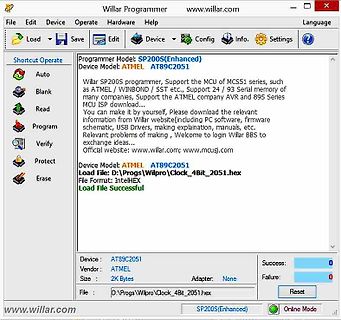
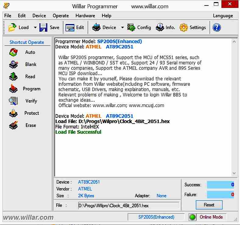
Load Save Edit Device Config Info Settings Programmer Model: SP200S(Enhanced) Device Model: ATMEL AT89C2051 Willar SP200S programmer, Support the MCU of MCS51 series, such as ATMEL / WINBOND / SST etc., Support 24 / 93 Serial memory of many companies, MCU ISP download... You can make it by yourself,
0000 ??ERAM_SIZE NUMBER 0000 ??FDATA_SIZE NUMBER 0000 ??RAM_SIZE NUMBER 0100 ??VERSION NUMBER 0120 ??_AT89C2051_ NUMBER 001B ??_AT89C4051_ NUMBER 001C ??_AT89C51ED2_ NUMBER 0026 ??_AT89C51IC2_ NUMBER 0024 ??_AT89C51ID2_ NUMBER 0025 ??_AT89C51RB2_ NUMBER 0021 ??_AT89C51RC2_ NUMBER 0022 ??_AT89C51RC_ NUMBER 0020 ??_AT89C51RD2_ NUMBER 0023 ??_AT89C51_ NUMBER 001D ??_AT89C52_ NUMBER 001E ??_AT89C55WD_ NUMBER 001F ??_AT89LP2052_ NUMBER 0001 ??_AT89LP213_ NUMBER 0003 ??_AT89LP214_ NUMBER 0004 ??_AT89LP216_ NUMBER 0005
ASEM-51 V1.3 Copyright (c) 2002 by W.W. Heinz PAGE 1 MCS-51 Family Macro Assembler A S E M - 5 1 V 1.3 ===================================================== Source File: C:\Users\BNoll\Documents\Mide51\MM\MM2
Guten Tag, ich suche einen Assembler + Linker für die Mikrocontroller der Atmel-Familie (AT89C51, AT89S51/52). OS = WINDOWS 10/11. Ich möchte zwei Assembler-Dateien zusammenfügen (main.asm + function.asm). Ich habe dafür Keil-C verwendet, leider habe ich aber nur die Eval-Funktion mit der
> Guten Tag, > ich suche einen Assembler + Linker für die Mikrocontroller der > Atmel-Familie (AT89C51, AT89S51/52). OS = WINDOWS 10/11. > Ich möchte zwei Assembler-Dateien zusammenfügen (main.asm + > function.asm). > Ich habe dafür Keil-C verwendet, leider habe ich aber nur die > Eval-Funktion
Läßt sich die Firmware des AT89C2051 auslesen oder sind die Lock Bits gesetzt? Falls sich die Firmware auslesen läßt stelle sie hier rein, dann kann man schauen wie die UART Kommunikation abläuft.
nebenbei noch Platz für sehr viele zusätzliche Befehle, wie dunkler, heller, EIN/AUS etc. Da die µC sehr wenig Speicherplatz haben, ist das Programm vermutlich in Assembler geschrieben und man muss auch beim SRAM auf den Verbrauch achten (musste ich damals auch, ich habe aber den AT89C4051 genommen
condition can used to set the field intensity, H, that flows parallel to a boundary. This is done by setting c 0o zero, and c 1o the desired value of H in units of Amp/Meter. Note that this boundary condition can also bestsed to prescribe ∂A/∂n = 0 at the boundary. However, this is unnecessary–the 1 order triangle
Aussagen von Keil zu den beiden Chips. Daraufhin hatte ich angenommen, PD geht in der Simulation beim AT89LP51.
Tendenz geht bei mir inzwischen doch wieder Richtung AT89C - die Nachteile bez. Simulation sind da deutlich geringer. Und der PIC läuft mir ja nicht weg.
sowieso nicht möglich ist, werde ich auch nicht versuchen, da durchzusteigen. Habe mir jetzt den Atmel AT89LP51RB2 ausgesucht, ist bei Mouser verfügbar. Der wird ordentlich von Keil supportet und kann weit mehr, als ich benötige. Zumindest konnte ich schon erste Simulationen erfolgreich durchlaufen.
Es gibt Gründe, warum ich einen Simulator benutzen möchte, um den erzeugten Code für meinen uC zu testen: Der uC arbeitet im Verbund mit anderen Schaltungsteilen, die noch in Entwicklung sind. Deren geplantes zeitliches Verhalten ist aber bekannt und vorgegeben: also wie sie auf Signale vom uC
shown in millimeters (inches) S M DIMENSIONS 6 B MILLIMETERS INCHES D 5 L MIN MAX MIN MAX A 0.89 1.12 .036 .044 A1 0.01 0.10 .0004 .0039 A2 0.88 1.02 .035 .040 3 6 E b 0.30 0.50 .0119 .0196 E1 c 0.08 0.20 .0032 .0078 ccc C B A D 2.80 3.04 .111 .119 1 2 E 2.10 2.64 .083 .103 E1 1.20 1.40 .048 .055
Temperature Range : -40 to 85 °C Storage Temperature Range : -40 to 85 °C Performance Data: No Load Stall Maximum Efficiency Maximum Power Current (A) 1.41 87.51 11.11 44.46 Efficiency (%) - - 71 - Output Power (W) - - 94.78 237.07
0038 FC 50 MOV A,R4 ;SEE IF ALL 4 SHIFTS ARE OVER. 0039 DD 51 XRL A,R5 ;IF R4=R5 SIGNIFYING OLD DATA, 003A C604 52 JZ START ;PROGRAM JUMPS TO START AT 0004 003C FC 53 DIGITSH: MOV A,R4 ;FOR NEW DATA, LOAD
IO-Pins nutzen zu können war ein großer Vorteil. Ich hatte mir auch einen Prommer selber gebastelt. Ein AT89C51 programmiert den Ziel AT89C51. Ein UV-Löschgerät mag ich nicht mal mit spitzen Fingern mehr anfassen. 1995 gabs dann den Keil C51, der erstaunlich kompakten Code erzeugte. Da konnte man sich
P. R. Coleman, R.C. Durfree; B. A. Worley, LandScan: A Global Population Database for Estimating Populations at Risk. Photogrammetric Engineering & Remote Sensing 2000. Vol. 66(No. 7): p. 849-857. Quelle: DLR 2010, S.
Resultate. Ich habe auch an einen 50pol. Universal-Tester gedacht. Hauptsächlich möchte ich erst mal USB-C und HDMI-Kabel testen. Geprüft werden soll natürlich primär auf Durchgang von einem Kabelende zum anderen. Als zweites aber auch auf Schlüsse zwischen den Adern selbst. Letzteres würde einseitig reichen
Ich habe mal nen Tester für bis zu 40 polige Flachkabel gebaut. Verwendet wurden 3 AT89C51 mit je 32 IO-Pins. Über die UART wurden sie kaskadiert. Alle 3 bekamen die gleiche Firmware. RXD des ersten wurde auf low gelegt, damit er weiß, daß er mit Testen anfangen soll. Es werden Muster
V (40V for 0.5 sec) Output current I 1.875 A OUT -0.5~33 Sustaining voltage at SW pin VSW (40V for 0.5 sec) V SOP8TP 1.4 MSOP8TP 1.45 1 TO252 2.8 Power dissipation P D W SOT23-6 1.2 SOT23-5 1.2 SOT89-5 1.45 SOP8TP 89.3 MSOP8TP 86.2 TO252 44.6 Thermal resistance R TH(j-a) °C/W SOT23-6 104.2 SOT23-5 104.2 SOT89-5 86.2 Operating junction temperature T 150 °C J(max) Operating temperature T OPR -40 to +85 °C Storage temperature T STG -55 to +150 °C The absolute maximum ratings are a set of ratings not to be exceeded
described by the ’quasi-static’ Maxwell’s equations written in differential form as ∇ × H = J, in Ω ,c (2.89) 18 2. POTENTIAL FORMULATIONS IN ELECTROMAGNETIC FIELD nonconducting region (airΓ B i(t) Γ Hn µ0 nc n Γ nc conducting region σ σE n n H,B Γ B Ω c Ω Γ Hc n µror B{ } H e Γ nc ΓE ΓB Fig. 2.9. Structure
Repetition rate (duty cycle): 0.01% Fast response time High temperature soldering guaranteed: 260°C/30 seconds at terminals ESD 30kV(Air), 30kV (Contact), per IEC-61000-4-2 Temperature Coefficient, 0.1% typical Whisker proof surface finish, tested per JEDEC JESD201A DO-214AC(SMA) MSL level
2 PLACES 2.0 3 औ͚ωδϞʔλέʔε໘ΑΓ▯▯▯ҎԼ▯ 9 motor mounting surface.ngth 2.0 max. from ø1.2 HOLE WEIGHT: 51g (APPROX) RF-370CB-11670 12.0V h I N 75 0.75 7,500 h 50 0.5 5,000 2 25 0.25 2,500 I0.3 N I Ts 0.4 ] [ A i 5 [mN·m] 10 N T r 50 [g·cm] 100 C R E TORQUE F U P E C S Headquarters 430 Matsuhidai, Matsudo-shi
EFM8BB52 - Demoboard herausgesucht und würde gerne wieder in Pascal programmieren. Ob ich mit Turbo51 da zum Ziel komme? Oder lohnt sich das Geld für den mikroE - Compiler? Warum kein C: ist mir zu unliterarisch und C++ zieht unnötig viel Zeug dazu / ist ineffizient, wenn man in Maschinen(raum)nähe
gibts fertig sogar für "SPI-huckepack" mit MCP2518 und trx, das wär nicht das Problem. Die älteren 51 Derivate AT89... mit internem CAN können meist nur Standard-CAN und kein FD. Auf der Karte ISOLATED-CAN-EK von Silabs ist ein EFM32 mit CAN-Hardware zusammengespannt. Die eur für was Fertiges wären
0 H R 10 0x000A OUT_M -Seconds internal 2 0 M R 11 0x000B OUT_S temperature value 2 0 S R 12 0x000C 2 1 R 13 0x000D T_IN external temperature F/C T_EX value key lock 2 1 F/C R 14 0x000E LOCK protection 2 0 - R/W 15 0x000F - PROTECT status constant 2 0 R/W 16 0x0010 CVCC voltage constant current 2 0
Symbol Parameter Unit 2 TO-220 TO-220FP TO-247 D PAK Rthj-case Thermal resistance junction-case 0.89 4.2 0.89 °C/W R thj-pcb Thermal resistance junction-pcb 60 °C/W Rthj-amb Thermal resistance junction-ambient 62.5 50 °C/W Table 3. Avalanche characteristics Symbol Parameter Value Unit AR Avalanche current
Symbol Parameter Unit 2 TO-220 TO-220FP TO-247 D PAK Rthj-case Thermal resistance junction-case 0.89 4.2 0.89 °C/W R thj-pcb Thermal resistance junction-pcb 60 °C/W Rthj-amb Thermal resistance junction-ambient 62.5 50 °C/W Table 3. Avalanche characteristics Symbol Parameter Value Unit AR Avalanche current

 Bild
Bild
 Bild
Bild