-
Datei
irsnd-main-avr.c
$ * * ATTINY2313 @ 8 MHz internal RC Osc with BODLEVEL 4.3V: lfuse: 0xE2 hfuse: 0xDC efuse: 0xF9 * * This program is free software; you can redistribute it and/or modify * it under the terms of the GNU General
in „Konzeption einer IR Fernbedienung“ · Mikrocontroller und Digitale Elektronik ·
-
Datei
8_Taster_1.bas
von 8 Schalter-Eingängen 'Siehe http://www.mikrocontroller.net/topic/214865#2138197 'Pinbelegung ATTiny2313: 'Eingänge an PortD 'Ausgänge an PortB $regfile = "attiny2313.dat" 'Portnamen vereinbaren $crystal = 1000000 'Takt vereinbaren $hwstack = 32 'Reg-Sicherung, Rücksprungadressen $swstack = 10 'Parameterübergabe
in „Schalter zu Taster“ · Mikrocontroller und Digitale Elektronik ·
-
Datei
irsnd-main-avr.c
fm Exp $ * * ATTINY2313 @ 8 MHz internal RC Osc with BODLEVEL 4.3V: lfuse: 0xE2 hfuse: 0xDC efuse: 0xF9 * * This program is free software; you can redistribute it and/or modify * it under the terms of the GNU General
in „IR Fernbedienung mit IRSND“ · Mikrocontroller und Digitale Elektronik ·
-
PDF
top2008.pdf
AT89C51EC2, AT89C51IC2, AT89C51RD2, AT89C51ED2, AT89C51ID2, AT89S54, AT89S58, AT89S64, AT90S1200, AT90S2313, AT90S4414, AT90LS4414, AT90S8515, AT90LS8515, AT90S4434, AT90S8535, AT90LS8535, AT90S4434, AT90LS4434, AT90S2333, AT90S4433, ATTINY11(Hi), ATTINY12(Hi), ATTINY13(Serial), ATTINY15L(Hi), ATTINY25, ATTINY26, ATTINY26L, ATTINY28L, ATTINY28V, ATTINY2313(DIP20), ATTINY2313V(DIP20),ATTINY2313, ATMEGA8, ATMEGA8L, ATMEGA16, ATMEGA16L, ATMEGA8535, ATMEGA8535L, ATMEGA8515, ATMEGA8515L, ATMEGA32, ATMEGA32L, ATMEGA48*PDIP28
in „[V] Top 853 Universal Programmer + 74er Tester“ · Markt ·
-
Datei
examples.c
: %k", 28123); Ausgabe: 28.123 %c : Ausgabe als Asciizeichen MCU : ATmega8, ATmega48 - ATmega328 ATtiny2313, ATtiny4313 ATtiny24 - ATtiny44 ATtiny25 - ATtiny85 16.02.2019 R. Seelig ---------------------------------------------------------- */ #include <string.h> #include <util/delay.h> #include <avr/
in „Ausgabe mittels printf über UART für ATmega / ATtiny“ · Projekte & Code ·
-
Datei
Check_Board_Pollin.bas
den produktiven 'Einsatz geeignet sind. 'Anpassung Kurt Pieper 'Original Pollin 'Testprogramm fuer ATTiny2313 'Pollin-Spiel Best.Nr.810148 '*************************************************************************************** $regfile = "ATtiny2313.dat" Lcd_db4 Alias Portb.0 Lcd_db5 Alias Portb.1 Lcd_db6
in „Messgeraetchen aus Pollin Spiel bauen“ · Mikrocontroller und Digitale Elektronik ·
-
PDF
doc1925.pdf
Device Support The system software currently supports the following devices in all speed grades: n ATtiny11 n AT90S4433 n ATtiny12 n AT90S4434 n ATtiny15 n AT90S8515 n ATtiny22 n AT90S8535 n ATtiny28 n ATmega8 n AT90S1200 n ATmega16 n AT90S2313 n ATmega161 n AT90S2323 n ATmega163 n AT90S2333 n ATmega323
in „STK500 als ISP“ · Mikrocontroller und Digitale Elektronik ·
-
PDF
stk500.pdf
Device Support The system software currently supports the following devices in all speed grades: n ATtiny11 n AT90S4433 n ATtiny12 n AT90S4434 n ATtiny15 n AT90S8515 n ATtiny22 n AT90S8535 n ATtiny28 n ATmega8 n AT90S1200 n ATmega16 n AT90S2313 n ATmega161 n AT90S2323 n ATmega163 n AT90S2333 n ATmega323
in „STK500 mit Breadboard“ · Mikrocontroller und Digitale Elektronik ·
-
Datei
Aqualicht-dcf-Gesteuert-V1_1_.bas
MANUELLE * '* EINGABE MÜSSTE DER MEGA8 VERWENDENT WERDEN, DA DIES NICHT NÖTIG IST WURDE * '* DER ATTINY2313 VERWENDET * '* PROGRAMM ERSTELLT AM 20.04.2008 VON MIKE KÖPPL (KOEPPLMIKE@AOL.COM) * '* COMPILER IST BASCOM 1.11.9.1 * '******************************************************************************* $regfile = "attiny2313.dat" $crystal = 4000000 $framesize = 128 $hwstack = 40 $swstack = 30 '---------- LCD Defineiren ----------------------------------------------------- Config Lcd = 16 * 2 Config Lcdpin = Pin , Db4
in „Sonnenauf - Untergang mit Dimmer“ · Mikrocontroller und Digitale Elektronik ·
-
Datei
mfc_ro7021.c
PR_ACK_TX 4 #define BYTE_TX 5 // Device dependant defines #if defined(__at90tiny26__) | defined(__attiny26__) #define DDR_USI DDRB #define PORT_USI PORTB #define PIN_USI PINB #define PORT_USI_SDA PORTB0 #define PORT_USI_SCL PORTB2 #endif #if defined(__at90Tiny2313__) | defined(__attiny2313__) #define
-
Datei
mfc_ro7021.c
PR_ACK_TX 4 #define BYTE_TX 5 // Device dependant defines #if defined(__at90tiny26__) | defined(__attiny26__) #define DDR_USI DDRB #define PORT_USI PORTB #define PIN_USI PINB #define PORT_USI_SDA PORTB0 #define PORT_USI_SCL PORTB2 #endif #if defined(__at90Tiny2313__) | defined(__attiny2313__) #define
-
Datei
Vogelscheuche.bas
* '* EXTERNE TIEFENENTLADESCHUTZSCHALTUNG an PIND.1 * '* MANUELLER TESTKNOPF an PIND.0 * '* * '* Attiny 2313 mit 4MHz interner Quarz * '* Made in Switzerland ;-) * '* Version 1.03 @ Juni 2012 * '* Autor P. Brandenberger * '******************************************************************************* $regfile = "attiny2313.dat" $crystal = 4000000 $framesize = 32 $hwstack = 10 $swstack = 32 '---------- LCD Defineiren ----------------------------------------------------- Config Lcd = 16 * 2 Config Lcdpin = Pin , Db4
in „Vogelscheuche Schaltung“ · Mikrocontroller und Digitale Elektronik ·
-
PDF
AVRDUDE-doc-5.5.pdf
They both feature simple firwmare-only USB implementations, running on an ATmega8 (or ATmega88), or ATtiny2313, respectively. 1.1 History and Credits AVRDUDE was written by Brian S. Dean under the name of AVRPROG to run on the FreeBSD Operating System. Brian renamed the software to be called AVRDUDE when
in „USB-ISP PRogrammer unter Ubuntu“ · PC Hard- und Software ·
-
Datei
SPIsourceATmega.txt
Datenübertragung per SPI ; Schaltung : SPI: MOSI, MISO, SCK ATMega8 zu ATTinys lt. Datenblatt ; ATMega8 - ATTiny2313 ; C1 - B0 ; C2 - B0 ; C3 - B1 ; C0: PIN für Taster ; C4: PORT für LED ;------------------------------------------------------------------------- ; Prozessor : ATmega8 ; Takt : 3686400 Hz ; Sprache
in „SPI Kopplung von ATmega8 und ATtiny 2313“ · Projekte & Code ·
-
 Bild
Bild
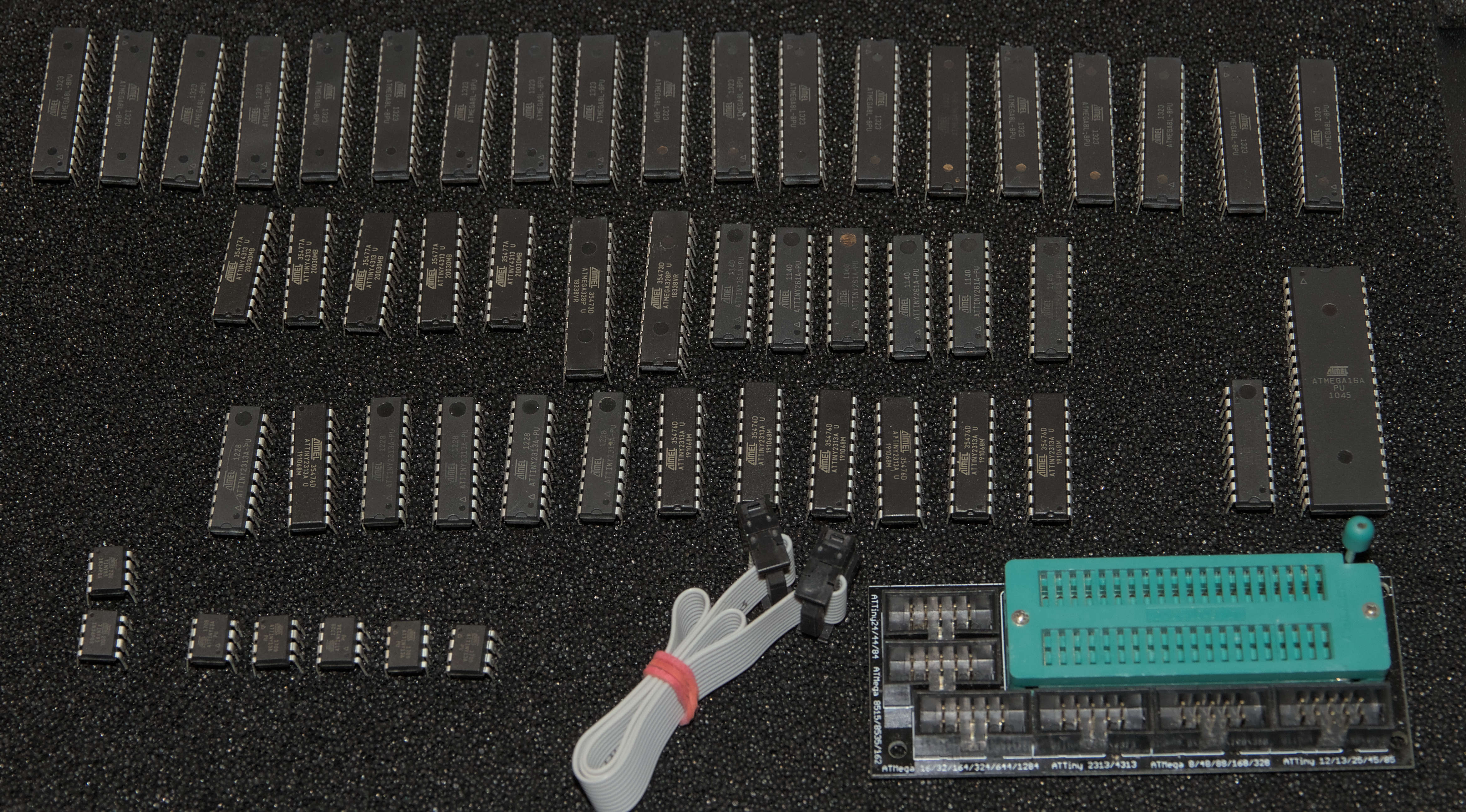
Verschiedene Mikrocontroller und ICs auf dunklem Untergrund
ATmega328P, ATmega168, ATmega8, ATmega4, ATmega16, ATmega32, ATmega64, ATmega128, ATmega2560, ATtiny2313, ATtiny45, ATtiny85
in „[V] Set: STK 500, Dragon, diverse ATtiny und -mega, passendes Buch, Zubehör“ · Markt · · Fotos
-
Datei
zeitausloeser.bas
'( Zeitausloeser fuer die Casio Exilim EX F1 mit Attiny 2313 fuer die Erzeugung von Serienbildern / Zeitraffer Der Ausloeser kann an die 3 Kabel des USB-Fernausloesers der Casio angeschlossen werden: Casio Usbkabel -> Zeitausloeser GND (Schwarz) -> GND
in „Zeitauslöser für Casio EX F1 mit attiny2313“ · Projekte & Code ·
-
Datei
tlc549.bas
Data - an PB.5 ' Clock - an PB.7 ' CS - an PB.6 ' Pollin Board - Pollin Spiel 810148 'Chip type 'ATtiny2313 'Achtung max. Volt beachten!!!!! '********************************************************** $regfile = "ATtiny2313.dat" Lcd_db4 Alias Portb.0 Lcd_db5 Alias Portb.1 Lcd_db6 Alias Portb.2 Lcd_db7
in „Messgeraetchen aus Pollin Spiel bauen“ · Mikrocontroller und Digitale Elektronik ·
-
Datei
AVRStrudio4.11b401_Release_Notes.txt
causes unstable operation when placing a breakpoint on line 65535 of an Assembler project SIMULATOR * ATtiny26: various fixes for Timer/Counter1. * ATtiny15: various fixes for Timer/Counter1. * Various fixes for most devices' Timer/Counter0: is now cycle-correct and fully functional. * Fixed problem with
in „AVRStudio4 v4.11 Build 401 Beta freigegeben“ · Mikrocontroller und Digitale Elektronik ·
-
PDF
stk500_ba_-2.pdf
Die Systemsoftware unterstützt zur Zeit folgende AVR’s in allen Ge- schwindigkeitsstufen (MHz): • ATtiny11 • AT90S4433 • ATtiny12 • AT90S4434 • ATtiny15 • AT90S8515 • ATtiny22 • AT90S8535 • ATtiny28 • ATmega8 • AT90S1200 • ATmega16 • AT90S2313 • ATmega161 • AT90S2323 • ATmega163 • AT90S2333 • ATmega323
in „deutsche version vom stk500 handbuch“ · Mikrocontroller und Digitale Elektronik ·
-
Datei
main.c
-------------------------------------------------* * 14-Apr-2014 ShaneG * * Template program for ATtiny85 C/asm projects. *--------------------------------------------------------------------------*/ #include <stdint.h> #include <stdio.h> #include <stdbool.h> #include <avr/io.h> #include <avr/interrupt.h
in „Kommunikation zwischen ATtiny85 und ATmega328p“ · Mikrocontroller und Digitale Elektronik ·
-
Datei
Values.txt
B40C1500 1 B2,54 1 AVR_XMEGA_A3_ 1 AVR-JTAG-10 1 AVR ISP 1 AVR 1 Aux_In 1 AUX 1 Ausgang 1 AtTINY45 1 ATTINY28 1 ATTINY26P 1 AT Tiny26 1 ATTINY24 1 ATTINY2313-20P 1 ATtiny2313 1 ATMEGA8-16P 1 ATMEGA640-16AU 1 ATMEGA48-20A 1 ATMEGA32U4-AU 1 ATMEGA2560-16AU 1 AT_MEGA16P 1 ATMEGA168-20A 1 ATMEGA164-20A 1 ATMEGA128_TQPF 1 ATiny2313 1 AT93C46 1 AT91SAM7X512-AU 1 AT91SAM7S128-AU 1 AT91RM9200_PQFP 1 AT90S2333P 1 AT90S2313P - War jetzt nur ein Beispiel-AVR 1 AT90S1200P 1 AT8C51SND1C 1 AT89S51 1 AT89C52P6 1 AT45DB321 1 AS1325 1 ANT
in „[KiCad] Bibliotheksaufbau - Konzeptideen gesucht“ · Platinen ·
-
Datei
AVRrescue.c
0x06, 0xC0, 00, 00}, // ATtiny15 {0x1E, 0x90, 0x07, 0x6A, 0xFF, 00}, // ATtiny13 {0x1E, 0x90, 0x08, 00, 00, 00}, // ATtiny9 {0x1E, 0x90, 0x0A, 00, 00, 00}, // ATtiny4 {0x1E, 0x91, 0x01, 0xDF, 00, 00}, // AT90S2313 {0x1E, 0x91, 0x02
in „AVR-Rescue: standalone Parallel HV-Programmer“ · Projekte & Code ·
-
Datei
IR_C.c
* * IR-LED und Batterietest: * * 1x lang = Batt ok * * 3x kurz = Batt schwach * * * * PROCESSOR: ATTiny2313, Intern 8MHz * * PINS: PD3 (Pin 7) Int1 Taster IN * * PD5 (Pin 9) IR OUT * * PD6 (Pin 11) LED OUT * * PB1 (Pin 13) AIN1 IN * * * * Pull-Up für Taster aktiviert? * * * * Version: 0.4 * * Date :
in „ATTiny geht leicht kaputt. Warum?“ · Mikrocontroller und Digitale Elektronik ·
-
Datei
diff-20100825.txt
2 lines +#define LCD_COLS 16 // 10col display (2*5) - only required for wrap #if defined (__AVR_ATtiny2313__) || defined (__AVR_ATtiny2313A__) @@ -265,6 +292,9 @@ extern int main (void) { uint8_t i; char buf[16]; + enum {FREQ_ID_HZ=0, FREQ_ID_KHZ, FREQ_ID_MHZ, FREQ_ID_GHZ}; + const char *a_freq_text
in „Reziproker Frequenzzähler+ Optimierte 64bit uint Routinen“ · Projekte & Code ·
-
Datei
User_def_chars.asm
************************************************** ;Test fuer LCD userdefinierte Charakters ;MCU Attiny4313 (resp. 2313); ;MCU Frequenz STK500-Board (unkritisch bis ca.4 MHz) ;LCD 2x16; HD44780 compatible ;RS=PB4; Enable=PB5; R/Wquer=GND ; PortB LCD Ausgabe: R/W=GND ; PB7 PB6 PB5 PB4 PB3 PB2 PB1 PB0
in „Lcd die 1000ste“ · Mikrocontroller und Digitale Elektronik ·
-
Datei
RFID_Tiny2313_U2770B.bas
Em4095 von ' www.mcselec.de übernommen und für den U2270B abgeändert ' Als Controller wird ein AT-Tiny 2313 verwendet. ' Sie handeln auf eigene Gefahr! ' Bei diesen Daten handelt es sich um Beispielanwendungen die nicht für den produktiven ' Einsatz geacht sind. ' Pollin Electronic gibt keine Garantien irgendeiner
in „Pollin RFID Entwicklungsboard“ · Mikrocontroller und Digitale Elektronik ·
-
Datei
chips.xml
<CHIPLIST> <CHIP> <NAME>ATtiny13A</NAME> <FLASH>1024</FLASH> <EEPROM>64</EEPROM> <SIG>0x0007901E</SIG> <PAGE>16</PAGE> <LFUSE layout="4">YES</LFUSE> <HFUSE layout="6">YES</HFUSE> <EFUSE>NO</EFUSE> <LOCK>YES</LOCK> <CALIB>YES</CALIB
in „extreme Burner AVR 1.4.3 + ATTiny Erweiterungen“ · Mikrocontroller und Digitale Elektronik ·
-
Datei
tm16xx_demo.c
Grundsaetzliche Funktionen des TM16xx mit 4 stelliger 7-Segmentanzeige MCU : alle AVR ( getestet ATtiny85, ATtiny2313, ATtiny44, ATmega8, ATmega328p ) F_CPU : 8 MHz intern Pinbelegung Controller TM16xx --------------------------- PB1 CLK PB0 DIO PB0 und PB1 sind mit jeweils 2,2 kOhm Pop-Up Wider- staenden
in „Siebensegment und Tasten ansteuern mit TM1651 \ TM1637“ · Projekte & Code ·
-
Datei
test11.c
*********/ //#define POLLIN_FUNK_AVR_EVALUATIONSBOARD #ifdef POLLIN_FUNK_AVR_EVALUATIONSBOARD // Attiny2313 Aufbau von Stefan #define F_CPU 8000000 #define VORTEILER 256 #else // Attiny24 Aufbau von Thomas (Bastler) #define F_CPU 1000000 #define VORTEILER 64 #endif #include <stdint.h> #include <avr/io.h
in „Tasterabfrage“ · Mikrocontroller und Digitale Elektronik ·
-
Datei
main.c
#ifndef __AVR_ATtiny2313A__ #define __AVR_ATtiny2313A__ #endif #include <avr/io.h> #include <avr/interrupt.h> #include <avr/sleep.h> #include <avr/wdt.h> //#define F_CPU 8000000UL // ATtiny2312A internal clock (CKDIV8
in „Ablufthaubensteuerung, Schaltung entstören“ · Mikrocontroller und Digitale Elektronik ·
-
Datei
beispiel.html
A3967SLB | A3977 | AD594/95 | AT89S52 | ATMEGA16 | ATMEGA64 | ATMEGA8 | ATMEGA8-16PI | ATMEGA8535 | ATTINY11 | ATTINY12 | ATTINY13DIP-SO | ATTINY13MLF | ATTINY15L | ATTINY16DIP/SO | ATTINY16MLF | ATTINY2313DIP/SO | ATTINY2313MLF | ATTINY24-44-84/DIP-SO | ATTINY24-44-84/QFN-MLF | ATTINY25-45-85/DIP-SO |
in „[KiCad] Bibliotheksaufbau - Konzeptideen gesucht“ · Platinen ·
-
PDF
AVR_Uebersichtstabelle.pdf
8 ATtiny13 1 0.064 64B + 32 reg 6 20 1.8-5.5 -- 1 2 -- -- -- -- Yes 4 Yes Yes Yes Yes No 9 6 Yes PDIP 8 SOIC 8 SOIC (EIAJ) 8 MLF 20 ATtiny15L 1 0.0625 -- 6 1.6 2.7-5.5 -- 2 1 -- -- -- -- Yes 4 Yes Yes Yes Yes -- 8 1(+5) -- PDIP 8 SOIC (208mil) 8 ATtiny2313 2 0.128 128 18 20 1.8-5.5 1 1 4 -- USI 1 USI Yes -- Yes Yes Yes Yes -- 8 2 Yes PDIP 20 SOIC 20 MLF 20 ATtiny24 2 0.128 128 12 20 1.8-5.5 1 1 4 -- USI -- USI Yes 8 Yes Yes Yes Yes -- 17 12 Yes MLF
in „Unterschied der AVR'S“ · Mikrocontroller und Digitale Elektronik ·
-
Datei
usiTwiSlave.c
############################################################## device defines #if defined( __AVR_ATtiny2313__ ) #define DDR_USI DDRB #define PORT_USI PORTB #define PIN_USI PINB #define PORT_USI_SDA PB5 #define PORT_USI_SCL PB7 #define PIN_USI_SDA PINB5 #define PIN_USI_SCL PINB7 #define USI_START_COND_INT
in „I2C Übertragungsproblem“ · Mikrocontroller und Digitale Elektronik ·
-
Datei
usiTwiSlave.c
############################################################## device defines #if defined( __AVR_ATtiny2313A__ ) // A anpassen #define DDR_USI DDRB #define PORT_USI PORTB #define PIN_USI PINB #define PORT_USI_SDA PB5 #define PORT_USI_SCL PB7 #define PIN_USI_SDA PINB5 #define PIN_USI_SCL PINB7 #define
in „Abfrage Taster durch USI vom Slave mit zwei AVR“ · Mikrocontroller und Digitale Elektronik ·
-
Datei
usiTwiSlave.c
############################################################## device defines #if defined( __AVR_ATtiny2313__ ) #define DDR_USI DDRB #define PORT_USI PORTB #define PIN_USI PINB #define PORT_USI_SDA PB5 #define PORT_USI_SCL PB7 #define PIN_USI_SDA PINB5 #define PIN_USI_SCL PINB7 #define USI_START_COND_INT
in „Attiny - Arduino I2C Problem“ · Mikrocontroller und Digitale Elektronik ·
-
Datei
LCD_C0802_04.inc
20.01.2013 ; ;*********************************************************************** ; ; tested on ATtiny2313 ; ; LCD Funktion ATtiny2313 ; ---------------------------------- ; LCD-connections: 1 GND GND ; 2 VDD (+5V) Vcc ; 3 Vo (pull down over 820 Ohm) ; 4 RS PD4 ; 5 R/W (GND) GND ; 6 E (enable) PD5 ;
in „AVR LCD lib für HD47780 (z.B. Pollin C0802-04)“ · Projekte & Code ·
-
Datei
uart.c
UART_TX_BUFFER_SIZE & UART_TX_BUFFER_MASK ) #error TX buffer size is not a power of 2 #endif #if defined(__AVR_AT90S2313__) || defined(__AVR_AT90S4414__) || defined(__AVR_AT90S8515__) || \ defined(__AVR_AT90S4434__) || defined(__AVR_AT90S8535__) || \ defined(__AVR_ATmega103__) /* old AVR classic or ATmega103 with one
in „Timerberechnung die hunderste“ · Mikrocontroller und Digitale Elektronik ·
-
Datei
uart.c
UART_TX_BUFFER_SIZE & UART_TX_BUFFER_MASK ) #error TX buffer size is not a power of 2 #endif #if defined(__AVR_AT90S2313__) || defined(__AVR_AT90S4414__) || defined(__AVR_AT90S8515__) || \ defined(__AVR_AT90S4434__) || defined(__AVR_AT90S8535__) || \ defined(__AVR_ATmega103__) /* old AVR classic or ATmega103 with one
in „Fehler beim kompilieren des Bootloadertoutorials in C“ · Mikrocontroller und Digitale Elektronik ·
-
Datei
uart.c
UART_TX_BUFFER_SIZE & UART_TX_BUFFER_MASK ) #error TX buffer size is not a power of 2 #endif #if defined(__AVR_AT90S2313__) || defined(__AVR_AT90S4414__) || defined(__AVR_AT90S8515__) || \ defined(__AVR_AT90S4434__) || defined(__AVR_AT90S8535__) || \ defined(__AVR_ATmega103__) /* old AVR classic or ATmega103 with one
in „Wie macht man solche Lichtmodes? Lauflicht, PWM und Co“ · Mikrocontroller und Digitale Elektronik ·
-
PDF
AVRMicrocontrollers_Peripheral_Integration.pdf
S S S M A A C A D T I Z 8 1 Q W R 8 1 1 C M C C P B W U U I S I S Q Q L E D E S S p (3) ü ü ü ü ATtiny4/5/9/10 6 0.5–1 0.032 1.8–5.5 12 10³ 4 2 1 4 ATtiny102/104 8/14 1 0.032 1.8–5.5 12 10 5/8 ü ü 2 2 ü ü 1 4 ATtiny13A 8–20 1 0.064 1.8–5.5 20 10 4 ü 2 ü ü ü ü 3 ü ATtiny20/40 12–20 2/4 0.128/0.256 1.8
in „Nachfolger von Atmega169“ · Mikrocontroller und Digitale Elektronik ·
-
Datei
Synth.asm
.nolist .include "tn2313def.inc" ; Define device ATtiny2313 .list .macro WriteSram ; (register, const) ldi XL, low(SRAM_START) ldi XH, high(SRAM_START) ldi rmp, 0 j0: cpi rmp, @1 breq j1 st X+, @0 inc rmp rjmp j0 j1: ldi XL
in „Attiny2313 Timer16 Bit, Normal Mode, unsauber“ · Mikrocontroller und Digitale Elektronik ·
-
Datei
0001-Visual-Studio-2015-Files.patch
Include="src\atmega668base.h" /> + <ClInclude Include="src\atmega8.h" /> + <ClInclude Include="src\attiny2313.h" /> + <ClInclude Include="src\attiny25_45_85.h" /> + <ClInclude Include="src\avrdevice.h" /> + <ClInclude Include="src\avrdevice_impl.h" /> + <ClInclude Include="src\avrerror.h" /> + <ClInclude
in „Simulavr unter Windows mit Visual Studio 2015 kompilieren“ · Mikrocontroller und Digitale Elektronik ·
-
Datei
LCD_I2C_01.asm
;*************************************************** ; Test TWI via USI-Interface ; MCU: ATMEL ATtiny4313 ; Clock: 4 MHz ; TWI/I2C-PortB PB7=SCL; PB5=SDA ; LCD: 4x20 SainSmart2004; HD44780 compatible ; P7 P6 P5 P4 P3 P2 P1 P0 ; D7 D6 D5 D4 LED ENA R|W RS ; Device slave address: $38 (PCF8574A) ;ATtiny2313
in „I2C Display einfache Frage“ · Mikrocontroller und Digitale Elektronik ·
-
Datei
Synth.asm
.nolist .include "tn2313def.inc" ; Define device ATtiny2313 .list .macro WriteSram ; (register, const) ldi XL, low(SRAM_START) ldi XH, high(SRAM_START) ldi rmp, 0 j0: cpi rmp, @1 breq j1 st X+, @0 inc rmp rjmp j0 j1: ldi XL
in „Attiny2313 Timer16 Bit, Normal Mode, unsauber“ · Mikrocontroller und Digitale Elektronik ·
-
Datei
Rinpuffer.asm
********* ; * ; *Titel: Musterprogramm Version 1.0 ; *Autor: André Grohmann ; *Datum: ; *Device: ATtiny2313 an ... MHz ; *Fuses: ; *Programmbeschreibung ; * ; *Hardware Anforderungen: ; *Software Funktionen: ; * ; *(C)2006 by Grohmann Letzte Änderung: ; *************************************************************** ; .NOLIST .INCLUDE "tn2313def.inc" ; Prozessortyp AT Tiny2313 .LIST ; ***************************************************************** ; Konstanten ; ***************************************************************** ; .EQU buffer_size
in „Ringpuffer AVR“ · Projekte & Code ·
-
Datei
IR_Repeater2.asm
********** ;* Read IR Signal from TSOP and modulate 36khz Osc. ;* ;* Jürgen Berger ;* ;* Target: ATtiny2313 ;* ;* Speed: 8Mhz (RC int) ;* ;* Version: 1.0 ;* ;* Date: 22.07.2007 ;* ;* ;* ;************************************************************************* .nolist .include "tn2313def.inc" .list .
in „IR Verlängerung“ · Mikrocontroller und Digitale Elektronik ·
-
Datei
rc5-tester.bas
'* Stand: 11.08.2007 '* '********************************************************** $regfile = "attiny2313.dat" ' AT Tiny2313 $crystal = 8000000 ' 8 MHz $lib "mcsbyte.lbx" ' Code etwas kleiner Config Lcdpin = Pin , _ Db4 = Portb.0 , Db5 = Portb.1 , Db6 = Portb.2 , Db7 = Portb.3 , _ E = Portb.4 , Rs
in „Bascom + RC5“ · Mikrocontroller und Digitale Elektronik ·
-
Datei
Kleines_LCD_Tutorial.htm
Ende SRAM ;ldi temp, high(RAMEND) ; nur bei AVR-MCUs mit ;out SPH, temp ; hoeherem Speicher als ATTiny2313 ser temp ; Portzuweisung out DDRB, temp ; Port B Ausgang fuer LCD rcall einschaltverzoegerung ; der Power-On-Self-Reset des LCD rcall lcd_routine ; muß erst abgewartet werden rcall textausgabe
in „AVR-Tutorial: LCD - Erweiterung lcd-routines.asm - Bitte um Feedback“ · Mikrocontroller und Digitale Elektronik ·
-
Datei
Modellauto_ICP.BAS
$regfile = "2313DEF.dat" 'es handelt sich um einen ATtiny2313 $crystal = 8000000 'der eingebauter RC-Oszillator läuft mit 8 Mhz $hwstack = 100 'im Speicher werden für den Hardware-Stack 100 Byte reserviert $swstack
in „Fragen zu ICP (Bascom)“ · Mikrocontroller und Digitale Elektronik ·
-
 Bild
Bild
Fehlermeldung beim Kompilieren eines AVR-Projekts
Test_CMPS14_UART.c -o Test_CMPS14_UART.o unknown MCU 'atmega328pb' specified Known MCU names: at90s2313 at90s2323 at90s2333 at90s2343 attiny22 attiny26 at90s4414 at90s4433
in „WinAVR für ATmega328PB“ · Mikrocontroller und Digitale Elektronik · · Screenshots