compatible with standard 8051 instruction set PWM, capture/compare, and frequency output modes with • 70% of instructions execute in 1-2 clock cycles watchdog timer function • 48 MHz maximum operating frequency • 6 x 16-bit general-purpose timers • Memory: • Communications and Digital Peripherals: • Up
ISO 56,70 7664 Beha AMP-320-EUR Zangenmultimeter ISO 56,70 8333 Beha CHB 15 AC/DC Current Clamp Meter ISO 56,70 8253 Beha CHB 5 Leckstromzange ISO 56,70 8009 Beha CHB35 Stromzange ISO 56,70 7822 Beha CHB37 AC/
Input Power Dissipation (Each Channel) PI — 15 mW Output Current (Each Channel) IO — 60 mA Emitter Base Reverse Voltage (HCPL-4701/070A) V EB — 0.5 V Output Transistor Base Current (HCPL-4701/070A) I — 5 mA B Supply Voltage V CC –0.5 18 V Output Voltage VO –0.5 18 V Output Power Dissipation (Each Channel
3.3V\25° working current 灵敏度阈值 不可调节 V SENS 110 UV Sensitivity threshold unadjustable 工作温度 W ST -20 70 ℃ working temperature 输出 Output 输出低电流 OL -5 5 mA Output Low Current 封锁时间 不可调节 2.3 S Lock Time unadjustable 延迟时间 不可调节 1 S Delay Time unadjustable 地址:惠州市惠城区潼侨镇宏村宏川路鑫永诚科技园 3 /9 电话(Tel):0752—7987222 网址(Web
not found or type un HTE Grade 3 RTF (Reverse Treat Foil) Copper Weight ½, 1 and 2 oz (18, 35 and 70 µm) available Thinner copper foil available Standard Material Offering: Prepreg Tooling of prepreg panels Glass Fabric Availability E-glass Square weave glass Mechanically spread glass Isola Group Isola
to Change without Notice 9 October 2, 2023 DATA SHEET Si8931/Si8932 100 100 90 90 80 80 ) ) d d ( 70 ( 70 N N S S 60 60 50 50 40 40 0.0 0.5 1.0 1.5 2.0 2.5 0.0 0.5 1.0 1.5 2.0 2.5 Input Signal Amplitude (V) Input Signal Amplitude (V) Figure 13. Si8931 Signal-to-Noise Ratio (dB) vs. Figure 14. Si8932
............................................................................................. 6 4 Base-band Characteristics .................................................................................................................... 9 5 Programming Via the Serial Interface ...................
LEAD PLASTIC SO *FIXED VERSION S8 PART MARKING Operating Temperature Range.................... 0°C to 70°C PINS 1 AND 8 ARE INTERNALLY Storage Temperature Range............... –65°C to 150°C CONNECTED IN SOIC PACKAGE 1302 Lead Temperature (Soldering, 10 sec)................. 300°C TJMAX 125°CJAθ = 100°C
TEMP RANGE PIN-PACKAGE A These inverters use external P-channel MOSFET switches, MAX774CPA 0°C to +70°C 8 Plastic DIP X allowing them to power loads up to 5W. If less power is MAX774CSA 0°C to +70°C 8 SO 7 required, use the MAX764/MAX765/MAX766 inverting MAX774C/D 0°C to +70°C Dice* 7 switching regulators
LEAD PLASTIC SO *FIXED VERSION S8 PART MARKING Operating Temperature Range.................... 0°C to 70°C PINS 1 AND 8 ARE INTERNALLY Storage Temperature Range............... –65°C to 150°C CONNECTED IN SOIC PACKAGE 1302 Lead Temperature (Soldering, 10 sec)................. 300°C TJMAX 125°CJAθ = 100°C
collector or output voltage to less than ten volts (Equation 2–27). When the transistor is on, the base resistor must be sized (Equation 2–28) to enable the input signal to drive enough base current into the transistor to saturate it. The transistor beta is 50. Review of Circuit Theory 2-9 Transistor
specifications apply for T = –55°C Ao +125°C for the UC1903; –40°C to +85°C for the UC2903; and 0°C to +70°C for the UC3903; +V = 15V; Sense Inputs (Pins 6–9 and Pin 15) = 2.5V; V 4 = 1.0V, T = T . IN PIN A J PARAMETER TEST CONDITIONS UC1903 / UC2903 UC3903 UNIT MIN TYP MAX MIN TYP MAX SUPPLY Input Supply
MC51F7424 晟矽微电 时基模块逻辑框图 PWM Time Base Block PWM1CR0- >[CTMOD] ClockControl t M CounterControl o r PWM1RLEN=0xAA PWM1CR2- P >[PLDEN] Rst Signal Dir Signal e c Fsys 0 Fpwm S And And Duty Resgiters PreScaler PWM clk PWM Counter PostScaler
compatible with standard 8051 instruction set PWM, capture/compare, and frequency output modes with • 70% of instructions execute in 1-2 clock cycles watchdog timer function • 48 MHz maximum operating frequency • 6 x 16-bit general-purpose timers • Memory: • Communications and Digital Peripherals: • Up
Leute, hab neulich meinen rgb-header bei meinem mainboard in die Luft gejagt und will jetzt meinen base visualizer mit meinem esp32 neu bauen. Ist eigentlich ganz einfach: Esp ließt Audiosignal vom PC und schickt dann ein Signal an meinen LED-Strip. Ich kenn mich da halt nicht so aus auf jeden Fall bekomme
Felix schrieb im Beitrag #7821506: > base visualizer Gemeint ist vermutlich "Bass". Eine Neuinterpretation der schon in den 70ern jeden Partykeller urgemüttlich machenden Lichtorgel. Früher reichte da eine Handvoll Analoggerümpel, heute
. Und so ein Fernschreiber war damals mit 110 bps schon schnell. Das "damals" ist übrigens etwa 60-70 Jahre her. fchk
Nein. Bei zwei Adernpaaren endest Du bei 100 MBit. GBit-Ethernet braucht alle 4 Adernpaare. 10Base-T1L ist 10MBit Single Pair Ethernet und geht bis 1000m über eine verdrillte Doppelader. fchk
average or peak level indicators, power meters and RF signal strength meters. Replacing conventional +70°C. The LM3915N-1 is Available in an 18- meters with an LED bar graph results in a faster lead PDIP Package. responding, more rugged display with high visibility that retains the ease of interpretation
Temperature Figure 7-10. Short-Circuit Supply Current (I CC ) and Power (P) vs Supply Voltage (V ) CC 70 40 60 35 30 A 50 A m m t t 25 e 40 e u u 20 C C l 30 l p p 15 S 20 S 10 I at V = 3.3 V, V = 3.3 V I at V = 3.3 V, V = 3.3 V 10 CC CC ISO 5 CC CC ISO ICCat VCC = 5 V, ISO= 3.3 V CC at VCC= 5 V, VISO=
PART NUMBER PACKAGE BODY SIZE (NOM) 1 M:OVP AIN_2P PGA 2nLPFrdeDriver Logical ADS868x TSSOP (38) 9.70 mm × 4.40 mm AIN_2GND 1 M:OVP & VB2 Interface CS 1 M: (1) For all available packages, see the orderable addendum at AIN_3P OVP 2nd-OrdeADC SCLK the end of the datasheet. AIN_3GND OVP PGA LPF Driver 1
. anders realisiert. Veit K. schrieb im Beitrag #7809559: > Nachteil: Vergleichsweise teuer (4,70€ pro Stück > bei Reichelt). Tja, Knowhow kostet bares Geld ;-) Lerne dazu und du kannst sparen.
einem Mosfet fließt ja kein (relevanter) Strom von Gate zu Source. Bei einem NPN aber ja schon von Base zu Emitter. Oder habe ich deinen Gedanken eventuell falsch verstanden?
- Eine BAS70-4 ist vorgesehen. - Die Verstärkung vom AD8421 korrigiert. - der LT wird auch mit +/- 15V versorgt. Werde den Eingangsschutz des AD8421 erstmal lassen. Er hat laut Datenblatt einen recht guten
pin5 gegen GND. Hielt auch nicht, LT und TVS defekt. Nun kommt der dritter Versuch mit einer BAS70-4 und ohne 1kOhm. - Es wird noch andere Einstellungen mit der Verstärkung geben. Etwas Luft nach oben gelassen.
Kommandos die zu den Anfangsbuchstaben passen. Aber Linuxer sind leidensfähig und irgendwie so 70ties.
Michael B. schrieb im Beitrag #7815785: > Aber Linuxer sind leidensfähig und irgendwie so 70ties. Kontext-sensitive Vervollständigung kennste nicht? https://opensource.com/article/18/3/creating-bash-completion-script
C A 20 A ( 15 O I 10 5 0 0 0.5 1 1.5 2 2.5 3 VOP (V) 80 AT90S2313 0839I–AVR–06/02 AT90S2313 Figure 70. I/O Pin Sink Current vs. Output Voltage I/O PIN SINK CURRENT vs. OUTPUT VOLTAGE Vcc 5V 70 T A 25˚C 60 T = 85˚C A 50 40 ) A ( 30 O I 20 10 0 0 0.5 1 1.5 2 2.5 3 VOL (V) Figure 71. I/O Pin Source Current
eine der freigewordenen Leitungen als Videoleitung benutzt. Einwandfreies Bild. Ist aber nur ein BAS ohne F. S/W ist nachts eh besser als Farbe. Man braucht da normalerweise kein Koaxialkabel bei der kurzen Strecke.
einmal einen leichten (ungemeldeten) oder fremdverursachten? Niemals mit einer Art 50er in den 60/70ern auf die Seite gelegt oder einfach nur bei Sonnenschein gefahren? Wer gewohnt ist, einen 40-Tonner Lastzug zu fahren und zu rangieren, macht das täglich ggf. millionenfach auf der Erde. Standard-PKW-Fahrer
turning knobs The turning knobs consist of the round knob shell (silver) and the integrated knob base. The coding of the shaft between timer and thermostat varies. Elma Order No. Turning knob timer T310 – TP695H LC20H – LC60H 200 000 5123 Turning knob timer T700 – T1060H / LC130H 200 000 5327 Turning
before removing the rear cover. Figure 4-15 for details. 1. Remove fixation screws [1] that secure the base assy, pull 4. Gently lift the rear cover from the TV. Make sure that wires out the base assy from the set. Refer to Figure 4-13 for and cables are not damaged while lifting the rear cover from the set
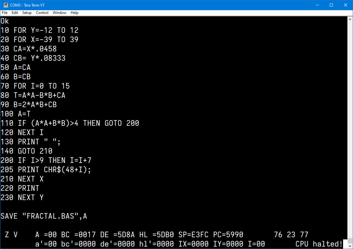
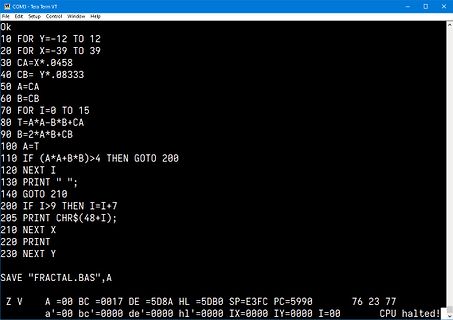
Tera Term VT
Ok
10 FOR Y=-12 TO 12
20 FOR X=-39 TO 39
30 CA=X*.0458
40 CB=Y*.08333
50 A=CA
60 B=CB
70 FOR I=0 TO 15
80 T=A*A-B*B+CA
90 B=2*A*B+CB
100 A=T
110 IF (A*A+B*B)>4 THEN GOTO 200
120 NEXT I
130 PRINT " ";
140 GOTO 210
200 IF I>9 THEN I=I+7
205 PRINT CHR$(48+I);
210 NEXT X
220 PRINT
230 NEXT Y
SAVE "FRACTAL.BAS",A
Z V A=00 BC =0017 DE=5D8A HL=5DB0 SP=E3FC PC=5990 76 23 77
a'=00 bc'=0000 de'=0000 hl'=0000 IX=0000 IY=0000 I=00 CPU halted!
.............. 67 FIGURE 2.21: ERROR RESTORED TO ZERO AFTER A DIFFERENTIAL VOLTAGE IS APPLIED .... 70 FIGURE 2.22: STEP RESPONSE OF SIMULINK MODEL OF ELECTROMETER ............................ 71 FIGURE 3.1: SIMPLIFIED SKETCH OF MECHANICAL TRANSDUCER ....................... .....74 FIGURE3.2: SOI MEMS
, N87 material LL3 = 12.10➭H C4 output capacitor - ceramic capacitors connected in parallel C C4 = 70.40➭F R10 series connection of DC resistance as stated: R R10 = 70.53mΩ 4mΩ shunt resistor to measure the output current i Out 20A, 3mΩ safety fuse - to prohibit cable ▯re power-multiplexer - two power
Supply Current vs Supply Voltage Figure 4. I/O Sink Current vs Output Low Voltage (V = 1.65 V) CC 70 100 VCC= 1.8 V V CC= 2.5 V 60 T = -40°C A TA= -40°C 80 TA= 25°C A 50 A TA= 25°C m m (K T A 85°C (K T = 85°C I I60 A IS40 IS t t e e r 30 r C C 40 k k i i S 20 S 20 10 0 0 0.0 0.1 0.2 0.3 0.4 0.5 0.6
15 show the 3-wire Control Interface Read and Write Timing Parameters and Diagrams, respectively. 70% SCLK 30% t t t t t S HSDIO HIGH LOW HSEN 70% tS SEN 30% 70% A6-A5, SDIO A7 R/W, A0 D15 D14-D1 D0 30% A4-A1 Address In Data In Figure 14. 3-Wire Control Interface Write Timing Parameters 70% SCLK 30%
). >>python geometrieAufgabe3.py Anteil der rosa Fläche: 29.31% Anteil der weißen Fläche: 70.69%
To make Musk's character fresh, the story would need a unique twist, perhaps his Mars colony as a base for a new world order, or using Starlink satellites for global surveillance. Visuals matter too. Bond villains have iconic lairs. Musk's SpaceX facilities or a Mars base could provide stunning visuals
cathode 18V -1.5 -2.7 voltage I Reference Input Current R = 10kΩ, R = OC 0.15 0.5 µA REF 1 2 TA = 0 to +70°C 0.05 0.3 REF deviation over full R1= 10kΩ, IREF(dev) temperature range TA= -40 to +85°C 0.1 0.4 µA R2 = OC T = -40 to +125°C 0.15 0.5 A TA = 0 to +70°C 55 80 Minimum cathode KMIN current for regulation
Ahmad schrieb im Beitrag #7771247: > JSs 29 BAS21 von Infineon > SAs 20 BSS123 von Infineon > 3FP 20 BC857B von Nexperia > 1G 20 > Z5F > A7p 20 BAV99 von Nexperia > Z7p 20 BZX84B12 von Nexperia > A1p 28 BAW56 von Nexperia > A4p 20 BAV70 von Nexperia. > Y8E
’ features are summarized as follows: • A 16-bit clock prescaler, from 2 to 65536 • A 54-bit time-base counter programmable to incrementing or decrementing • Able to read real-time value of the time-base counter • Halting and resuming the time-base counter • Programmable alarm generation • Timer value

 Bild
 Bild
 Bild