genericPartNumber=csd25402q3a&fileType=pdf Beispiel N-MOSFET: https://www.mouser.de/datasheet/2/196/irlml6244pbf-1228275.pdf Zwischen ESP Ausgang und Gate sollte man sicherheitshalber einen Widerstand von 300 Ohm setzen, damit der Umschaltimpuls auf 10mA begrenzt wird. THT wird schwierig.
kannst ja ruhig auf 220Ω runter gehen, um die Verluste zu minimieren. Oder du nimmst den MOSFET IRML6402 in SMD. Die stehen beide in meinem oben verlinkten PDF drin, mit Erklärung der Vor- und Nachteile, sowie Schaltungsempfehlungen.
viele Störeinflüsse von außen werden "ausgeglichen" - damit könnte ich erstmal leben 4. Die FETs (IRLML6402PBF) haben einen RDSon von 65 mOhm, das bedeutet bei den maximal möglichen 500 mA einen Spannungsabfall von 32,5 mV, das ist auf jeden Fall zu verkraften. Mir ist es erst einmal wichtig das es
einen BSS84, genommen ist immer geplatzt, obwohl er die 30mA locker können müsste. Jetzt ist ein IRLML6402 drin jetzt klappt es. Die erste Zelle fängt an zu Balancieren, habe jetzt den Strom auf 30mA runtergedreht, bis alle Zellen voll geladenen sind. Erstes Fazit, Transistor wurde einfach vergessen
deutlich bessere Wahl als Bipolartransistoren. Als SMD-FETs benutze ich gerne die BSS138 (N-FET) und IRLML6402 (P-FET), beide natürlich Logic-Level und bezahlbar sowie gut erhältlich.
ESD-Schäden, ganz sicher kann ich es nicht sagen. Das waren ganz normale FET, hauptsächlich BSS123 und IRLML6402. So eine ähnliche ist das: https://www.reichelt.de/ESD-Erdungsmaterial/ESD-MATTE-1200/3/index.html?ACTION=3&LA=446&ARTICLE=110009&GROUPID=600&artnr=ESD+MATTE+1200&SEARCH=ESD%2BMatte Die
dimensioniert. Ein wenig viel wuerde ich sagen. Sparsemer ginge es heute mit einem p-Kanal FET. Z.B. dem IRLML6402, und ein Widerstand von 470 Ω in Reihe dazu. Dem eigentlichen Ausgang koennte man noch 10 kΩ parallelschalten, damit man mit dem Oszi auch etwas sieht, wenn mal nichts angeschlossen ist. :)
Der Arduino Uno wird mit 5V versorgt und der Treiber (PIC) läuft mit 3,2V. Der Pmos ist ein IRML6402 https://www.infineon.com/dgdl/irlml6402.pdf?fileId=5546d462533600a401535668c9822638 Arduino High: U_gs=5V-3,2V=+1,8V -> Mosfet Off Arduino LOW: U_gs==v-2,8V=-2,8V -> Mosfet On Unklar sind mir
> sondern über einen Schalttransistor Ein IRLML6402, das waer mein Favorit zum Schalten der IR-Diode, hat ein Rds(on) von 0.065 Ohm. Und ein FET sollte es schon sein, um die LiO-Zelle bestmoeglich zu nutzen. Mit einer CR2032 und geschaetzten
Buchsenleiste des Raspberry Pi eine Schaltung mit IR-Empfänger, MCU (hier 89LPC922), LM2950-3,0 und einem IRLML6402 als Leistungsschalter aufgesteckt. Gate des IRLM6402 wird über einen 10k Pull-Up auf 5V gezogen und vom 5-Volt toleranten Open-Source Ausgang Pi_Off des MCU angesteuert. Auf der Platine des Raspberry
5V +5V +5V K 8 0 2 J K3 1 R 2 2 1 0 6 5 4 3 2 4 R27 PD3 P P P P P P P P PC1 ms1 B PD4 PC0 ms2 8 0 IRLML6402 10 +5V GND IC2 ADC7 endls1 9 n F n 4 VCC GND 2 0 0 0 3 GND AREF L B 1 1 1 R T9 Q5 2 3 1 VCC ATMEGA168(TQFP32) ADC6 endls2 C C C D PB6 5 6 7 0 1 2 3 4 AVCC F PB7 P P P P P P P P PB5 SCK n 0 20MHz
5V +5V +5V K 8 0 2 J K3 1 R 2 2 1 0 6 5 4 3 2 4 R27 PD3 P P P P P P P P PC1 ms1 B PD4 PC0 ms2 8 0 IRLML6402 10 +5V GND IC2 ADC7 endls1 9 n F n 4 VCC GND 2 0 0 0 3 GND AREF L B 1 1 1 R T9 Q5 2 3 1 VCC ATMEGA168(TQFP32) ADC6 endls2 C C C D PB6 5 6 7 0 1 2 3 4 AVCC F PB7 P P P P P P P P PB5 SCK n 0 20MHz
mit entsprechender Beschriftung. Als Transistoren empfehle ich NDP6020P (THT, TO220) oder IRML6402 (SMD, SOT23). Du brauchst aber auf jeden Fall anständige Schwellwertschalter davor. Und dann kommt vielleicht heraus, dass N-MOSFET besser passen. Das wären dann IRLZ44N (THT, TO220) oder IRLML6344
einmal mit LTSpice testen. Aber irgendwie finde ich diese Transistoren NDP6020P (THT, TO220) oder IRML6402 (SMD, SOT23) nicht. LTspice hat anscheinend keine sehr große Auswahl der Bauelemente. Welche kann man stattdessen nehmen. Es gibt mehrere Zenerdioden aber hauptsächlich mit 12V. Was sind eigentlich
B L PTT_IN Q10 7 L L1 1k Q8 F I 22-27-2041-04 22-27-2021-02 R40 R45 B TX+8V TX+12V X8-1 X6-2 10µH IRLML6402 TX 470 M X8-3 7 4 X8-4 4 R B B GND GND GND GND GND GND PTT_OUT Q11 7 F R46 M C 470 M V 7 2 4 R GND C C L2 X7-1 VOX_IN 22-27-2021-02 10µH X7-2 GND D D PTT-Steuerung (C) 2015 DJ2AT 1 2 3 4 5 6 1
Spezielle (HV, mehr Leistung etc z.T. in grösseren Gehäuseformen) MOSFETs: - 2N7002 - IRML2502 - IRLML 6402 - IRLML5203 - Diverse SO-8 - Die Schwergewichte dann wieder alles in TO-220 Dioden: - die üblichen Verdächtigen: 4148,BAT54-S/C,SD103CW - MURS120T3, MBRS140T3G - jede Menge Spezial/HF
max 55V, max 30A, 35 mOhm On-Widerstand Gatespannung kompatibel mit 5V-Controllern. R, D, I, C PDF IRLML2502 0,17 max 20V, max 4,2A (cont.), 45 mOhm On-Widerstand SOT23 SMD-FET, extrem niedrige V_GS_th, bei niedrigem R_DS_on R, D PDF BS170 0,10 max 60V, bis 500mA, 5Ω On-Widerstand veraltete Technik, aber
Siehe auch: MOSFET-Übersicht Bezeichnung Preis [ ] Beschreibung Anwendungen Lieferant Daten- blatt IRLML6401 0,20 max -12V, ca -4,3A (cont.), ca. 0,05Ω On-Widerstand (bei VGS -4,5V) SOT-23 SMD FET, extrem niedrige V_GS_th, bei niedrigem R_DS_on R, D PDF Infineon IRLML6402 0,21 max -20V, ca -3,7A (cont
P-Kanal-MOSFET gelöst. Bauteile: 1* 10µF KerKo 1* 1µF KerKo 1* 100nF KerKo 3* BCW66H npn 1* IRLML6402 1* SS14 2* 1kOhm 2* 10kOhm Da die Last nur über den P-FET läuft, kann das Teil sogar richtig was schalten; der IRLML6402 verknust laut Datenblatt 4,2A bis 20V.
mal eine Tag-/Nachtschaltung mit sehr geringem Standby Stromverbrauch. Fotodiode BPW34, 680K und IRLML 2502, Diese Schaltung habe ich zum Steuern der "Flacker Kerzen" Bis um die 800K ist möglich. Wichtig war nur, dass es ein LL Fet ist, denn diese Kerzen und Lichterketten werden ja meist mit
Hallo zusammen, ich habe den Transistortester von Markus F. (Version 2.1) erfolgreich nachgebaut. Da ich mich etwas mit der AVR-Programmierung auskenne, habe ich den Quellcode analysiert und verändert. Die wichtigsten Änderungen sind: Entfernung aller Texte und Parameterdaten aus dem EEprom in den Programmspeicher.(Vorteil: Programmierung in einem Rutsch, es kann nicht mehr dazu kommen, daß EEprom und Flash-Speicher nicht zueinander passen) Für die Kapazitätsmessung wird die Zeitmessung mit dem Timer1 des AVR zusammen mit dem Komparator durchgeführt. Speziell für kleine Kapazitäten
100nF C62 C D D +3V 2k 2k 33k T 1 1 1 1 N C 1 / D4 F L6 N N G S 1 2 I D D _ F V CD1 2.2uF/6.3V n G G IRLML6402 D DCMI_D0/USART6_TX 3 4 USART6_RX D X X X E C20 C16 + . 1 E/D 4 0 FB0805/600R/200mA(201209-601) SOFT_SCL 5 6 SOFT_SDA M C21 4 8 3 2 _ T _ R 1 / VDD OTG_HS_VBUS NA(ESDA6V1L) 1 USB-OTG L1 L2 SD_D3
power to external logic circuits. A suitable device would be an International Rectifier (www.irf.com) IRLML6402, or equivalent. It is recommended that a “soft start” circuit consisting of a 1kΩ series resistor and a 0.1μF capacitor are used to limit the current surge when the MOSFET turns on. Without the
voltage exceeds the OUT PART NUMBER DESCRIPTION voltageandtheinput supplyisremoved, or theLTC4067 IRLML6402 P-channel 16V is put into suspend or shutdown modes, the CHRG pin FDR8508P Dual P-channel 16V is forced into a high impedance state. If a bad battery If the OVP pin is high, the power path from
external logic circuits. A suitable device could be a Fairchild NDT456P, or International Rectifier IRLML6402, or equivalent. It is recommended that a “soft start” circuit consisting of a 1K series resistor and a 0.1 uF capacitor are used to limit the current surge when the MOSFET turns on. Without the
external logic circuits. A suitable device could be a Fairchild NDT456P, or International Rectifier IRLML6402, or equivalent. It is recommended that a “soft start” circuit consisting of a 1K series resistor and a 0.1 uF capacitor are used to limit the current surge when the MOSFET turns on. Without the
external logic circuits. A suitable device could be a Fairchild NDT456P, or International Rectifier IRLML6402, or equivalent. It is recommended that a “soft start” circuit consisting of a 1K series resistor and a 0.1 uF capacitor are used to limit the current surge when the MOSFET turns on. Without the
external logic circuits. A suitable device could be a Fairchild NDT456P, or International Rectifier IRLML6402, or equivalent. It is recommended that a “soft start” circuit consisting of a 1K series resistor and a 0.1 uF capacitor are used to limit the current surge when the MOSFET turns on. Without the
power to external logic circuits. A suitable device would be an International Rectifier (www.irf.com) IRLML6402, or equivalent. It is recommended that a “soft start” circuit consisting of a 1kΩ series resistor and a 0.1μF capacitor are used to limit the current surge when the MOSFET turns on. Without the
power to external logic circuits. A suitable device would be an International Rectifier (www.irf.com) IRLML6402, or equivalent. It is recommended that a “soft start” circuit consisting of a 1kΩ series resistor and a 0.1μF capacitor are used to limit the current surge when the MOSFET turns on. Without the
power to external logic circuits. A suitable device would be an International Rectifier (www.irf.com) IRLML6402, or equivalent. It is recommended that a “soft start” circuit consisting of a 1kΩ series resistor and a 0.1μF capacitor are used to limit the current surge when the MOSFET turns on. Without the
power to external logic circuits. A suitable device would be an International Rectifier (www.irf.com) IRLML6402, or equivalent. It is recommended that a “soft start” circuit consisting of a 1kΩ series resistor and a 0.1μF capacitor are used to limit the current surge when the MOSFET turns on. Without the
power to external logic circuits. A suitable device would be an International Rectifier (www.irf.com) IRLML6402, or equivalent. It is recommended that a “soft start” circuit consisting of a 1kΩ series resistor and a 0.1μF capacitor are used to limit the current surge when the MOSFET turns on. Without the
power to external logic circuits. A suitable device would be an International Rectifier (www.irf.com) IRLML6402, or equivalent. It is recommended that a “soft start” circuit consisting of a 1kΩ series resistor and a 0.1μF capacitor are used to limit the current surge when the MOSFET turns on. Without the
power to external logic. A suitable device to do this is an International Rectifier (www.irf.com) IRLML6402, or equivalent. It is recommended that a “soft start” circuit consisting of a 1kΩ series resistor and a 0.1µF capacitor is used to limit the current surge when the MOSFET turns on. Without the

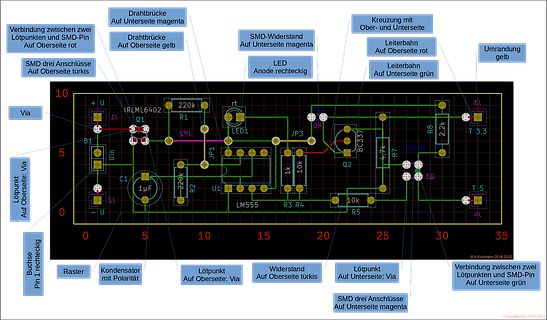
 Bild
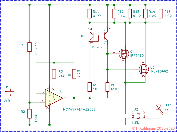
Bild
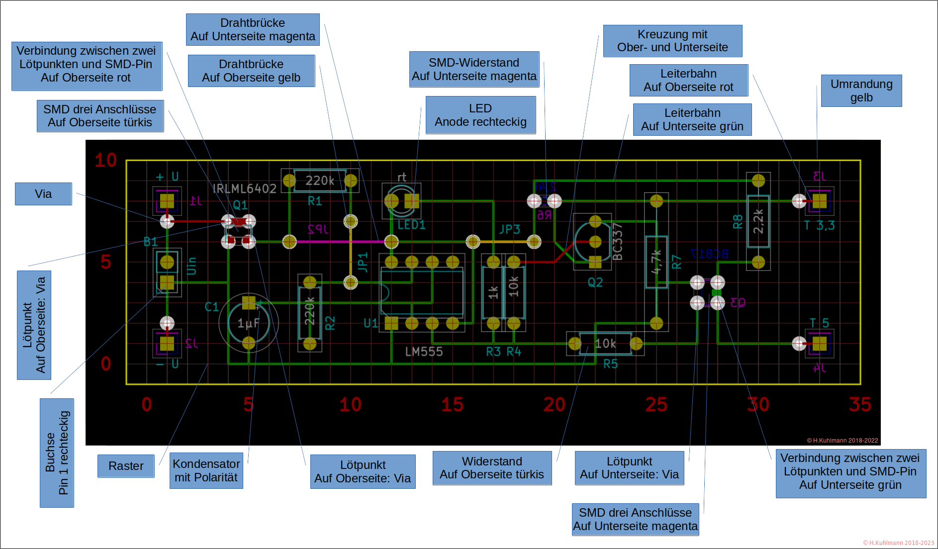
 Bild
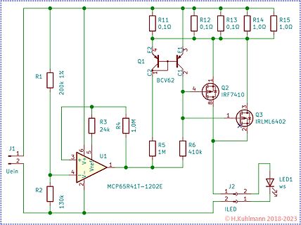
Bild