-
 Bild
Bild
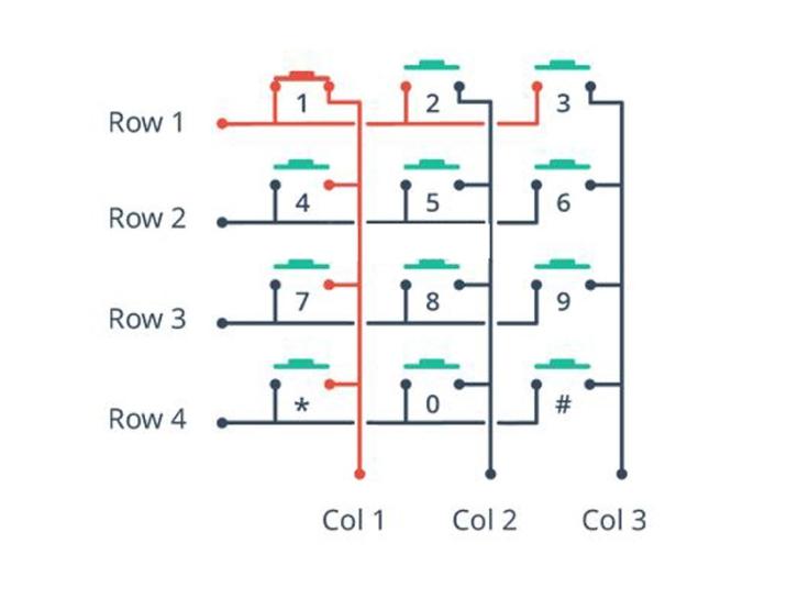
Schematische Darstellung einer Matrix-Anordnung
Row 1 1 2 3 Row 2 4 5 6 Row 3 7 8 9 Row 4 * 0 # Col 1 Col 2 Col 3
in „Keypad 3x4 with Row + Column LEDs“ · Mikrocontroller und Digitale Elektronik · · Diagramme
-
PDF
CH454DS1.PDF
tubes respectively. For LED Nixie tubes with less than 17 segments, the word-driven pins DIG7 ~ DIG0 are connected to the cathodes of 8 LED Nixie tubes respectively. The CH454 can also be connected to a 16×8 matrix LED array or
in „Viele Drucktaster und LEDs ansteuern“ · Mikrocontroller und Digitale Elektronik ·
-
PDF
XW28-MOD_Datasheet.pdf
a • Supports up to 32 buttons, arranged in a 8x4 keyboard controller for up to 64 keys in a 8x8 matrix, or up to 12 buttons connected direct matrix. • Enable output to signal suspend mode to • Custom keyboard layout programmable via external circuitry USB • Mouse emulation mode pin selectable at run
in „SpinWarrior28R4“ · Mikrocontroller und Digitale Elektronik ·
-
Datei
main.cpp
#endif #define STRINGIFY(x) #x #define TOSTRING(x) STRINGIFY(x) using namespace Eigen; DigitalOut led1(LED1); //MatrixXf A; //VectorXf b; int main() { printf("Hello from " TOSTRING(TARGET_NAME) "\n"); printf("Mbed OS version: %d.%d.%d\n\n", MBED_MAJOR_VERSION, MBED_MINOR_VERSION, MBED_PATCH_VERSION)
in „Lib Eigen (C++) auf STM32F429, Geschwindigkeit okay?“ · Mikrocontroller und Digitale Elektronik ·
-
PDF
Schematic__1_.pdf
3.3V +5V +3.3V +5V GND GND R12 R13 R14 R15 1kR 1kR 1kR 1kR 1 1 Turnstile Response 2 3 R16 2 3 R17 PI_LED_RING OUT_LED_RING PI_LED_MATRIX OUT_LED_MATRIX +3.3V 1kR 1kR B Q4 Q5 B BSS138 BSS138 R18 U6 TS_INPUT1_A 1 6 1kR 2 5 TS_INPUT1_C 3 4 BUZZER NC TS_INPUT1 4N35 BZ1 R19 U7 2 BUZZER TS_INPUT2_A 1 6 1kR 1
in „Hilfe benötigt! Pi Compute Module 4 Carrier Board ohne Funktion!“ · Mikrocontroller und Digitale Elektronik ·
-
Datei
LED_cude_test.25.12.2012.c
/* * LED_cude_test.c * * Created: 25.12.2012 19:39:46 * Author: Nikolaj */ #include "avr/io.h" int8_t const reihen[10] = {0, 128, 1, 64, 2, 32, 4, 16, 8, 255}; int8_t const spalten[9] = {0, 1, 2, 4, 8, 16, 32, 64, 128}; int main(void) { PORTE.DIRSET = 0xFF; /* PORTE als Ausgang. Matrix 74ACT573(Dx8) */ PORTC.DIRSET = 0xFF; /* PORTC als Ausgang. Matrix (8xLE(74ACT573)) */ PORTH.DIRSET = 0xFF; /* PORTH als Ausgang. 74HCT273D(Ebene) */ PORTA.DIRSET = 0xFF; int pause=0; while(1) { PORTA.OUTCLR
in „Probleme mit 74ACT573“ · Mikrocontroller und Digitale Elektronik ·
-
Datei
OV7670_Uno-mod.ino
AEC/AGC control 7 */ #define REG_BD60MAX 0xab /* 60hz banding step limit */ #define MTX1 0x4f /* Matrix Coefficient 1 */ #define MTX2 0x50 /* Matrix Coefficient 2 */ #define MTX3 0x51 /* Matrix Coefficient 3 */ #define MTX4 0x52 /* Matrix Coefficient 4 */ #define MTX5 0x53 /* Matrix Coefficient 5 */
in „Brauche Unterstützung beim OV7670 (bzw. SCCB)“ · Mikrocontroller und Digitale Elektronik ·
-
Datei
OV7670_Uno-FiFo_320.ino
AEC/AGC control 7 */ #define REG_BD60MAX 0xab /* 60hz banding step limit */ #define MTX1 0x4f /* Matrix Coefficient 1 */ #define MTX2 0x50 /* Matrix Coefficient 2 */ #define MTX3 0x51 /* Matrix Coefficient 3 */ #define MTX4 0x52 /* Matrix Coefficient 4 */ #define MTX5 0x53 /* Matrix Coefficient 5 */
in „Brauche Unterstützung beim OV7670 (bzw. SCCB)“ · Mikrocontroller und Digitale Elektronik ·
-
PDF
m_mops386a_p389m115.pdf
device fulfils the fire-protecting requirements of IEC/EN 60950. MOPS/386A User s Guide 31 LCD Dot-Matrix Interface Kontron 17.2 Backlight A series resistor (4Ω) connects Pin 15 with VCC (+5V). You can plug in a LED backlight directly on Pin 15 and Pin 16. 17.3 Configuration Because the LCD dot-matrix
in „Kontron PC-104 MOPS386A board from Bender Unimet 1000 ST“ · Mikrocontroller und Digitale Elektronik ·
-
Datei
PeDa_4x4_Matrix.c
LED_PORT PORTC #define LED0 0 #define LED1 1 #define LED2 2 /************************************************************************ * Tastermatrix 4x4: * *---------------------------------------------
in „4x4 Tastenmatrix Problem“ · Mikrocontroller und Digitale Elektronik ·
-
PDF
AS1106_07_Datasheet_EN_v1.pdf
Enable Register (see page 10) must be set to ‘00000000’ as described in Table 9 on page 10. Single LEDs in a column can be Note: For a multiple-digit dot matrix, multiple AS1106 devices must be cascaded.nt G and bit D7 corresponds to segment DP. Figure 14. Application Example as LED Dot Matrix Driver d l i Diode Arrangement SEG G 8x8 LED Dot Matrix SEG G 8x8 LED Dot Matrix a SEG E SEG E l v SEG B SEG B i l SEG DP G SEG DP s t A t AS1106/ DIG0:7 s nAS1106/ DIG0:7 DIN107 DVDD VBAT t e DIN1107 V DD VBAT Processor CLKD/CSN a m 9.53kΩ n
in „LED 8x8 Matrix mit AS1107 und AT90PWM316“ · Mikrocontroller und Digitale Elektronik ·
-
PDF
5x7matrix_gross.pdf
AgilentHDSP-H571,HDSP-H573 5x7GeneralPurposeDotMatrixDisplays 53.2mm(2.09Inch)Package Data Sheet Features • 5 x 7 Dot matrix – Dot diameter 5.0 mm – Dot pitch 7.62 mm Description • High Efficiency Red (HER) This display comprises 7 rows by 5 and common
in „Laufschrift 5x7 Dotmatrix aber wie?“ · Mikrocontroller und Digitale Elektronik ·
-
PDF
PT6312.pdf
compatible with µpD16312. FEATURES • CMOS technology • Low power consumption • Key scanning (6 x 4 matrix) • Multiple display modes: (11 segments, 11 digits to 16 segments, 6 digits) • 8-Step dimming circuitry • LED ports provided (4 channels, 20mA max.) • 4- Bits general purpose input ports provided •
in „VFD Driver IC - Wieso negative Treiberspannung?“ · Mikrocontroller und Digitale Elektronik ·
-
PDF
ERA026200LED.pdf
02101300-01-02 E M E R G I N G D I S P L A Y MODEL NO. VERSION PAGE TECHNOLOGIES CORPORATION ERA026200(LED TYPES)(RoHS) 1 8 9. DETAIL DRAWING OF DOT MATRIX 0.447 0.437 0.149 0.139 3 7 4 R G B R . 0 0 R G B R 5 7 0 3 132*(RGB)*65 DOTS 58.994 UNIT : mm SCALE : NTS NON-SPECIFIDE TO LERANCE±IS 0.1 DOT NON-SPECIFIDE
in „Display nur mit Datenbus“ · Mikrocontroller und Digitale Elektronik ·
-
Datei
main.c
/* * RGB_led_matrix_steuerung_v2.c * * Created: 25.11.2014 05:31:18 * Author: Prophecy ----------------CONNECTION---------------------------- PA0 --- Treiber Kathode ROT 0 (Active High) PA1 --- Treiber Kathode ROT
in „7x7 RGB-LED matrix problem“ · Mikrocontroller und Digitale Elektronik ·
-
PDF
Arduino_Project_Handbook_25_Practical_Projects_to_Get_You_Started.pdf
(Figure 24-1) is a grid of 64 red, green, and blue LEDs. You can create the colors of the rainbow by controlling each LED individually and by mixing colors together. Figure 24-1: An RGB LED matrix The LED matrix has a total of 32 pins (Figure 24-2); 8 pins
in „LED Driver mit µC“ · Analoge Elektronik und Schaltungstechnik ·
-
Datei
LED_16X64_RELEASE_0_41_.txt
// Steuer Program 16X64 LED MATRIX mit SD Karte, audio auswertung und bedientasten //Variablen für Hauptrotinen (loop und timing) int time = 2000; boolean timeFM = 0; int NEXTANZEIGENAME = 1; byte Modus = 0; //Variablen SCREANSAVER
in „ASCII code in Marix 2D Array umwandeln“ · Mikrocontroller und Digitale Elektronik ·
-
Datei
ws6812_test_zwo.c
fill_background(bg_red, bg_green, bg_blue, bg_white); for (uint8_t i = 0; i < ANZAHL_SPALTEN; i++) { led[pixel[zeile_akt][i]].r = ring_red; led[pixel[zeile_akt][i]].g = ring_green; led[pixel[zeile_akt][i]].b = ring_blue; led[pixel[zeile_akt][i]].w = ring_white; } ws2812_setleds_rgbw(led,ANZAHL_LEDS); zeile_akt++; } } int main(void) { create_matrix(ANZAHL_ZEILEN, ANZAHL_SPALTEN); while(1) { fill_background(0,0,0,0); ws2812_setleds_rgbw(led,ANZAHL_LEDS); _delay_ms(500); moving_ring_zeilen(100, 10, 0, 10, 0, 100, 100, 0); _delay_ms(500); fill_background
in „LED-Matrix mit light_ws2812-library; Ansteuerungsgeschwindigkeit“ · Mikrocontroller und Digitale Elektronik ·
-
Datei
tools.h
----------------------- */ /* -------------- Öffentliche Funktionen Prototypen ----------- */ /* Matrix Init und löschen */ void InitMatrix(); void ClearMatrix(uint8_t); void life(); /* Matrix übertragen in LEDs */ void SendMatrix(); /* Bitbanding: Setze ein Bit einer Variablen auf 0 oder 1 */ void set_bit
in „STM32F1xx: Wie GOL am "Leben" halten?“ · Mikrocontroller und Digitale Elektronik ·
-
PDF
EW40420YLY.pdf
(LED TYPES) 3 NUMBERING SYSTEM PolarizMode Backlight Code value Transflective LED L Transmissive LED M BColorght Value Yellow-Green Y E W 4 0 4 2 0 G L Y LCD type + Code LCD color Value STN + Y Yellow-Green
in „4x40 LCD Display ohne HD Controller ansteuern.“ · Mikrocontroller und Digitale Elektronik ·
-
PDF
MicroSwitch_SD.pdf
keyboards were designed for two-of-N encoding using dual-output sensors, SD keyboards are more commonly matrix scanned using single-output sensors. SW was designed to avoid the expense and complexity of matrix scanning, but by the time SD was introduced, matrix scanning was a normal approach. History The oldest-known
in „Hall Sensor in Computertastatur ersetzen“ · Mikrocontroller und Digitale Elektronik ·
-
PDF
Manual_DotMatrixGenerator.pdf
Anleitung zum Dot Matrix Generator Quelle: http://www.instructables.com/id/LED-Scolling-Dot-Matrix-Font-Graphics-Generator- /?ALLSTEPS Online Version (abgespeckt): http://box-fish.com/matrix-tool.php# Step 1: Open the Generator File - Get Excel Setup Download and open the "Dot_Matrix_Font_Generator.xls" file. It contains macros which means you may have trouble opening it depending on your security settings. I promise that it is safe. You will need to enable and/or allow the macros
in „Fontgenerator für LED-Matrix 8x16 gesucht“ · Mikrocontroller und Digitale Elektronik ·
-
PDF
keller.pdf
C:\Users\Kevin\Desktop\LED Dot-Matrix v2\main.c #include <p18cxxx.h> #pragma config MCLRE = ON #pragma config PWRT = ON #pragma config OSC = INTIO2 #pragma config FSCM = OFF #pragma config IESO = OFF #pragma config BOR = OFF
in „FLUSSDIAGRAMM“ · Mikrocontroller und Digitale Elektronik ·
-
Datei
model.asm
MOVLW b'11110000' ;Konfiguration PortB 1-4 Ausgänge 4-8 Eingänge MOVWF 86h BCF 03H,5 main ;Abfrage Matrix Matrix movlw b'00000001' movwf 86h btfsc 06h,4 call Tasteneun ;Taste 9 btfsc 06h,5 call Tastef ;Taste F btfsc 06h,6 call Tastee ;Taste E btfsc 06h,7 call Tasted ;Taste D movlw b'00000010' movwf 86h
in „Codeschloss mit PIC [Assembler Code]“ · Mikrocontroller und Digitale Elektronik ·
-
PDF
PT6311.PDF
three-line serial interface. FEATURES • CMOS Technology • Low Power Consumption • Key Scanning (12 x 4 matrix) • Multiple Display Modes: (12 segments, 16 digits to 20 segments, 8 digits) • 8-Step Dimming Circuitry • LED Ports Provided (5 channels, 20 mA max.) • 4- Bits General Purpose Input Ports Provided
in „PT6311 und microcontroller atmel?“ · Mikrocontroller und Digitale Elektronik ·
-
PDF
LM118KFWL2_Solomon_Disp.PDF
2 OF BACKLIGHTING B Φ = 10° —— 20 —— cd/m 5,6 SOURCE θ = 0° λp —— 565 570 575 nm NOTE (6) : DOT-MATRIX TYPE LED NOTE (1) : DEFINITION OF θ AND Φ Z (Normal) eye Y (θ = 180°) ∅ 2 LCD ∅ 1 X (θ= -90°) X’ (θ= 90°) θ LED Y’ (θ = ° ) NOTE (2) : DEFINITION OF VIEWING ANGLE Φ 1 AND Φ 2 K Φ < 10 ° <Φ2 t R s 1.4
in „Geiger Counter Sparkfun“ · Mikrocontroller und Digitale Elektronik ·
-
PDF
EW32F50YLY.pdf
AREA → VIEWING ANGLE 7 7. OUTLINE DIMENSIONS AA. 95.9→ 95.98 , 71→971.98 9 9. DETAIL DRAWING OF DOT MATRIX REVISED THE ENTIRE PAGE 02101300-01-02 E M E R G I N G D I S P L A Y MODEL NO . VERSION TECHNOLOGIES CORPORATION 32F50(LED TYPES) 2 T A B L E O F C O N T E N T S NO. I T E M PAGE ==================
in „Extrem schwere Frage“ · Mikrocontroller und Digitale Elektronik ·
-
Datei
main.c
Interruptroutinen/ISRs) ändern können // damit sie nicht vom Compiler wegoptimiert werden uint16_t led[12]; // Matrix für LED-Zeilen uint8_t col_cnt; // zählt Zeilen durch (für Multiplexing) volatile uint8_t sec_flag; // wird gesetzt, wenn eine Sekunde vergangen ist volatile uint8_t sleeptimer; // zählt
in „PingPong (ATMega8A) - Resetproblem“ · Mikrocontroller und Digitale Elektronik ·
-
Datei
uart_echo.c
SYSCTL_USE_PLL | SYSCTL_OSC_MAIN | SYSCTL_XTAL_16MHZ); // // Enable the GPIO port that is used for the on-board LED. // ROM_SysCtlPeripheralEnable(SYSCTL_PERIPH_GPIOF); // // Enable the GPIO pins for the LED (PF2). // ROM_GPIOPinTypeGPIOOutput(GPIO_PORTF_BASE, GPIO_PIN_2); // // Enable the peripherals used by this
in „Probleme mit Array und launchpad lm4F120XL“ · Mikrocontroller und Digitale Elektronik ·
-
Datei
MAX7219_8.ino
UNO # Programming Language: Wiring / C /Processing /Fritzing / Arduino IDE # # Objective: Scrolling LED dot Matrix # # Operation: Scrolls a message over a 64x8 LED dot matrix ################################################################################ //****************************************************************************** // visit this web page for further information about MaxMatrix library // https://code.google.com/p/arudino-maxmatrix-library/ //****************************************************************************** */ #include <MaxMatrix.h> #include <avr/pgmspace.h>
in „LED Matrix MAX7219 8x8 an Arduino will nicht.“ · Mikrocontroller und Digitale Elektronik ·
-
Datei
LEDMatrix.cpp
/** * LED Matrix library for http://www.seeedstudio.com/depot/ultrathin-16x32-red-led-matrix-panel-p-1582.html * The LED Matrix panel has 32x16 pixels. Several panel can be combined together as a large screen
in „Atmega / Arduino - Library für 64x32 Dot Matrix Display“ · Mikrocontroller und Digitale Elektronik ·
-
PDF
BTHQ_128064AVD-FSTF-12-LED02White-COG.pdf
COG-BTD12864-04 1. General Description x▯ 128 x 64 Dots FSTN Positive Black & White Transflective Dot Matrix LCD Module. x▯ Viewing Angle: 12 o’clock direction. x▯ Driving duty: 1/65 Duty, 1/7 bias. x▯ ‘Epson’ S1D10605D04B (COG) Dot Matrix LCD Driver or equivalent. x▯ FPC x▯ White LED02 backlight. 2. Mechanical
in „Einschaltproblem“ · Mikrocontroller und Digitale Elektronik ·
-
Datei
logiclevel_dice.cpp
: 40 bzw. 24 mA). * * 2/ Nomenklatur: * =============== * M = LED in der Mitte des Würfels (für die Würfelbilder 1, 3 und 5) * L = LED-Paar von links unten nach rechts oben (für die 2, 3, 4, 5, 6) * R = LED-Paar von rechts unten nach links oben (für die 4, 5, 6) *
in „Retro-Projekt: NE555 basierter Elektronischer Würfel in THT“ · Projekte & Code ·
-
PDF
tps92661-q1.pdf
TPS92661 device features open LED protection • Automotive headlight systems as well as open and short LED fault reporting via the • High-Brightness LED Matrix Systems serial interface. The TQFP package features a feed-through topology
in „LED Serienschaltung mittels Transistor schalten“ · Analoge Elektronik und Schaltungstechnik ·
-
PDF
I2CselectionGUIDE.pdf
PCF2119 LCD controller/driver 0 1 A0 SAA2116 LCD controller/driver 1 0 A0 PCF8531 34 × 128 pixel matrix driver 1 0 A0 PCF8548 65 × 102 pixels matrix LCD driver 1 0 A0 PCF8549 65 × 102 pixels matrix LCD driver 1 0 A0 PCF8578/9 Row/column LCD dot matrix driver/display 1 0 A0 PCF8568 LCD row driver for dot matrix displays 1 0 A0 PCF8569 LCD column driver for dot matrix displays 1 A1 A0 PCF8535 65 × 133 pixel matrix LCD driver 1 1 A0 OM4085 Universal LCD driver for low multiplex rates 1 1 A0 PCF8566 96-segment
in „Übersicht I2C-Adressen“ · Mikrocontroller und Digitale Elektronik ·
-
PDF
PitschLight_Doku_V1.2.pdf
PAL tauglichen Ausgang (CVBS) haben. Das rechte Bild zeigt eine Möglichkeit, mit Hilfe einer HDMI-Matrix und eines HDMI2AV Konverters ein solches PAL-Signal zu erzeugen und gleichzeitig den Bildschirm mit HDMI zu versorgen. Die Stromversorgungen für PitschuLight und LED-Streifen sind hier nicht gezeigt
in „Ambilight mit STM32F4discovery und TVP5150AM1“ · Mikrocontroller und Digitale Elektronik ·
-
Datei
Entprelltest.c
der Erkennung eines Tastendrucks per externem Interrupt mit Entprellung. Zu Beginn wird eine Grüne LED eingeschaltet, und jeweils beim Drücken invertiert und auch beim Loslassen des Tasters invertiert, so dass die LED immer leuchtet, wenn der Taster losgelassen ist, und nicht leuchtet, wenn der Taster
in „AVR Einstieg / Probleme mit Programm Interrupt“ · Mikrocontroller und Digitale Elektronik ·
-
PDF
12-2012_Weihnachtsbaum.pdf
R R R R R R R 7 R8...R13 = Die Schaltung in Bild 1 ist unkompliziert: Die 4 20 680R; 820R; 1k 56 LEDs sind in einer Matrix angeordnet (8 mal 7 VDD 1 MCLR/VPP RC7 18 17 Elemente), die Matrix ist mit dem Mikrocontroller 2 IC1 RC6 16 RA0 RC5 unmittelbar verbunden. Der Mikrocontroller schal- 3 RA1 RC4 15
in „Alternative zu PIC18F2685“ · Mikrocontroller und Digitale Elektronik ·
-
PDF
datasheet.pdf
dynamic drive LT1455M LT1456M Absolute Maximum Ratings (Ta=25˚C) Electrical Characteristics (V CC=5V,V LED=5V,Ta=25˚C) Parameter Symbol Rating Unit Parameter Symbol MIN. TYP. MAX. Unit Supply voltage for IC V CC -0.3 to +6.0 V Supply voltage for IC V CC 4.75 5.0 5.25 V Supply voltage for LED V LED -0.3 to
in „Netzteil 5V 200A gesucht“ · Mikrocontroller und Digitale Elektronik ·
-
Datei
main.c
/* * 7x7_RGB_LED_MATRIX.c * * Created: 26/03/2019 00:23:12 * Author : WINDOWS10_GAMING ATMEGA32 mit 24,5 MHz Quarz ----------------CONNECTION---------------------------- PA0 --- Treiber Kathode ROT 0 (Active High) PA1
in „[avr-gcc]7x7 RGB matrix code problem“ · Mikrocontroller und Digitale Elektronik ·
-
 Bild
Bild
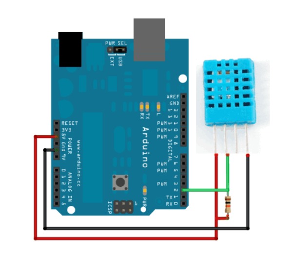
Arduino Uno mit Matrix-LED-Modul und Widerstand
PWR SEL, USB, EXT, AREF, GND, 13, 12, 11, 10, 9, 8, 7, 6, 5, 4, 3, 2, 1, 0, DIGITAL, PWM, PWM, PWM, TX, RX, ANALOG IN, 5V, GND, 3V3, RESET, www.arduino.cc, Arduino, ICSP, PWR
in „DS1621 mit Arduino Uno in SimulIDE 1.1.0-SR2 at Rev 260312“ · Mikrocontroller und Digitale Elektronik · · Fotos
-
Datei
3x4matrix.bas
' Reads a standard 3X4 keypad and assembles No in Digits variable, then displays ' Led used is just to show program running 2K2 from port pin via Led to + ' Setup for 89S8252. Use appropriate port assignments for other processors ' Uses Active Low, so no extra components needed. Chip internal tieups are utilised ' Mike Gill . B M Electronics UK 01422 839321 Config Debounce = 40 ' Set Key Pad Debounce to 40 Ms ''''''''''''''''''''''''''''''''''''''''''''''''''''''''''''''''''''''''''''''''''''''''''''' 'OUTPUTS All Active High Taste1 Alias P3.0 ' zu schaltende Ausgänge Taste2 Alias P3.1 Taste3
in „Bascom und 90S8252“ · Mikrocontroller und Digitale Elektronik ·
-
PDF
Getting_Started_with_CapSense.pdf
VDD R Vsrc Vsnk CapSense Controller LED CapSense Controller R LED CapSense CapSense button button Vsrc Vsnk VDD VDD ON OFF ON OFF t ON OFF ON OFF t LED in Sourcing Mode LED in Sinking mode 2.7.1.1.2 Advanced LED Effects For user interfaces
in „PT1-Filter in C“ · Digitale Signalverarbeitung / DSP / Machine Learning ·
-
PDF
BTHQ_128064AVE.pdf
BATRON COG-BTHQ12864-05 32 32 128 X 64 DOTS 8 VDD 1 GND /CS1 /RES A0 /WR /RD D0 ~ 8 D7 VOUT DOT MATRIX CAP3- LCD DRIVER CAP1+ 'EPSON' CAP1 - SED1565D0B (COG) CAP2- CAP2+ V1 V2 V3 V4 V5 VR C86 IRS + YELLOW GREEN LED02 BACKLIGHT - Figure 2: Block Diagram Data Modul AG - www.data-modul.com 6 BATRON 3.
in „Frage Graphik-LCD BTHQ128064“ · Mikrocontroller und Digitale Elektronik ·
-
PDF
Z-LASER_Produktdatenblatt_ZM18B.pdf
Schutzklasse IP67, wasser- und staubdicht »» M18 Außengewinde für einfache und vielseitige Befestigung »» LED Betriebsanzeige »» Überspannungsschutz mit Surge/Spike Schutz Bildverarbeitung Fahrzeugbau Holz Lebensmittel Medizin Metall Stein Textil / Leder 108 ZM18B 93 61 2 M18 x 1 Steckverbinder Ø M12 x 1 Mechanische
in „Spitzenwertdetektor Laserstrahlmessung“ · Analoge Elektronik und Schaltungstechnik ·
-
PDF
EW162B0YLY.pdf
INPUT/OUTPUT LINES 11 DB4 4 BIT : DB4 - DB7 12 DB5 8 BIT : DB0 - DB7 13 DB6 14 DB7 POWER SUPPLY FOR LED 15 VLSS 0V (GND) LED BACKLIGHT (CATHODE) 16 VLED POWER SUPPLY FOR LED LED BACKLIGHT (ANODE) 17 NC 18 NC POWER SUPPLY FOR LED 19 VLSS LED BACKLIGHT (CATHODE) 0V (GND) 20 VLED POWER SUPPLY FOR LED LED BACKLIGHT (ANODE) MODEL NO. VERSION PAGE E M E R G I N G D I S P L A Y TECHNOLOGIES CORPORATION 162B0(LED TYPES) 4 8 1 0 . POWER SUPPLY 1 0 . 1 POWER SUPPLY FOR LCD MODULE VDD LCD DISPLAY VO VDD
in „Probleme bei 16x2 LCD mit KS0066 (EW162B0YLY)“ · Mikrocontroller und Digitale Elektronik ·
-
PDF
DLO2416.pdf
Z SIEMENS YYWW .260 (6.60) FEATURES .160 .020 Luminous (4.06 .51) .100 16 pl.tensity Code • Dot Matrix Replacement for DL2416T (2.41) (.46) (2.54) at Seating Plane • 0.200" 5 x 7 Dot Matrix Characters ref. .002 (.05) 18 pl. • 128 Special ASCII Characters for English, German, TOLERANCE: XXX .01 (.25)
-
PDF
HDSP2112_1x8_Dotmatrix_LED_parallel.pdf
ideal for applications where displaying eight or x XY stackable (HDSP-250x) more characters of dot matrix information in an aes- x 128 sharacter ASCII decoder thetically pleasing manner is required.These devices are x Programmable functions 8-digit, 5 x 7 dot matrix, alphanumeric displays and are all packaged
in „[V] Intelligente LED-Matrix-Displays, HDSP 2112, SCF 5740, PD 2435“ · Markt ·
-
PDF
FYM-23881ABxxx.pdf
DOT MATRIX DISPLAY FYM-23881ABxxx-xx ¡ö Features: ¡⁄60.20mm (2.3) F5.0 dot matrix LED display. ¡⁄Low current operation. ¡⁄Excellent character apperance. ¡⁄Easy mounting on P.C.boards or sockets. ¡⁄I.C.compatible
in „Treiberstufen High und Low side“ · Mikrocontroller und Digitale Elektronik ·
-
PDF
schaltplan.pdf
2 GND GND 37 LED_81 LED_82 LED_83 LED_84 LED_85 LED_86 LED_87 LED_88 LED_89 LED_90 LED_91 LED_92 LED_93 LED_94 LED_95 LED_96 VDD3V3 3 3V3 IO23 36 GPIO23 SPI ESP_EN 4 EN IO22 35 SCL C15 C14 SINK5 GPIO36 5 SENSOR_VP TXD0