D 1 3 D 1 E OSDDNG 1 0 1 M 0 G 41 31 B1NET E1 5 W S W S 9 8 R 20 1 X 31 2 S S F 01 RM 7Q 7 D F 7R 21 21 A1NET 3 4 6SK/ 1SK KLCS_I PS M11 PCHS6Q 6 9 A 6R 11 11 6 5 2 5 3 PCTS21 PCTS 5Q 5 4 0 1 O 5R 01 01 3 p 2 3 S T S 5 T EO/31 EO 4Q 4 R 2 W L 4R 9 9 3 ) 4 0 G D S C 0 1 0 S C "2ODEL 41 SD 3Q 3 8 D 7
Size:15mm*17.3mm*3mm Working temperature: -30℃-105℃ Bluetooth® Specification v5.0 Zigbee 3.0, Base Device Behavior, CoreApplications Stack R21, Green Power ● Serial transparent transmission; 2.4 GHz RF transceiver ● Smart power plug/Smart LED light; Support BLE & Zigbee coexistence ● Sensor networks
allowable characters and format of the test vectors is identical to the JEDEC Test Datei: MANUAL.TXT Seite 21 von 38 Vector Format. The VEC file format test vectors are very similar to the JEDEC test vectors with only one difference. This difference is that the JEDEC format requires that every pin on the device
kein root), einen hohen Port für SSH (und dann nicht 222, sondern z.B. 51736) und kein FTP/FTPS (Port 21/20), sondern SFTP, SCP und rsync -e ssh (das läuft dann alles über SSH), wieder 2 Ports zu. Der hohe Port für SSH ist erstaunlich erfolgreich, ich hatte früher Port 229 und trotzdem tausende IPs in Fail2ban
Aber ich kriege Lust, mir mal anzuschauen, was da teilweise bei den versuchten code injections base64-codiert verschickt wurde. Oder vielleicht ist genau das die Falle, wer weiß. Wenn ich da jetzt versuche, zu jeder der geloggten IPs den ISP oder Hoster zu ermitteln und abuse-eMails zu verschicken
> Eine Frage zum Thema Multiplexing mit PNP/NPN hab ich noch. > Die IV-18 Schaltung schaltet die -21V für Gitter/Segmente mit BC557 > (PNP). Nicht *minus* 21V. Plus 21V. Den Anhang im komischen Maker-Forum kann ich nicht sehen. Aber wenn überhaupt, dann liegt die Glühkathode auf -21V und die Gitter
Axel S. schrieb im Beitrag #7790961: > Nicht minus 21V. Plus 21V. Den Anhang im komischen Maker-Forum kann > ich nicht sehen. Aber wenn überhaupt, dann liegt die Glühkathode auf > -21V und die Gitter/Anoden werden von den Transistoren auf GND bzw. wohl
der Geschwindigkeit vollkommen. Danke für die hilfreichen Tips. [code] Public Sub find_mac(ip_base as string) // ip_base like "192.168.10." var uc(255) as URLConnection //List of HTTP-Sockets var ff(255) as FolderItem //List of temporary files var path as string = SpecialFolder.Temporary.NativePath
~/Downloads$ sudo nmap -sP 10.17.67.0/24 Starting Nmap 7.94SVN ( https://nmap.org ) at 2024-12-15 21:10 CET Nmap scan report for _gateway (10.17.67.1) Host is up (0.000069s latency). MAC Address: 50:91:E3:25:B8:D0 (Unknown) Nmap scan report for 10.17.67.3 Host is up (0.00044s latency). MAC Address
Zelsius C5 Standard M-Bus Telegram, Standard Base Type The main Heat meter REQ_UD2: 10 7B FE 79 16 Main telegram C5 Fertigungsversion Raw data Information Format Note Header 68 9D 9D 68 RSP_UD, length 68 LL LL 68 08 00 72 C Field, Adress, CI Field
dieser Spannung ihren > Dienst verweigern. Der TO soll es einfach nur probieren und endlich im 21. Jahrhundert ankommen! Primärzellen sind Mittelalter!
Rainer Z. schrieb im Beitrag #7776242: > Der TO soll es einfach nur probieren und endlich im 21. Jahrhundert > ankommen! Primärzellen sind Mittelalter! Das ist Ansichtssache. Für Uhren o.ä., die teilweise viele Jahre mit einer Primärzelle laufen, nehme ich _keine_ Akkus. Für die demnächst
RSQINT RDSINT X STCINT Skyworks Solutions, Inc. • Phone [949] 231-3000 • sales@skyworksinc.com • www.sk21orksinc.com 207003A • Skyworks Proprietary Information • Products and Product Information are Subject to Change without Notice • October 29, 2024 AN332 Command 0x21. FM_SEEK_START Begins searching for
werden! "Angst wegnehmen" - Juhu, werdet alle zu Lemminge: https://youtu.be/F_RmG9WB4BE?t=27 Base Jumping ist auch ein schönes Hobby und wieso sind die Foristen in der Pflicht andere in die richtige Spur zu bringen? Wenn die Motivation nur extern ist, dann wird das sowieso nichts auf Dauer. Dann
Benutzername galaktus Vorname Klaus Nachname K. Firma Angemeldet seit 13.10.2024 21:51 Beiträge 25 Schorsch M. schrieb im Beitrag #7772851: > So ist es, die Moderatoren sind Teil des Problems! Benutzername schorschm Vorname Schorsch Nachname Meier Firma Angemeldet
Ahmad schrieb im Beitrag #7771247: > JSs 29 BAS21 von Infineon > SAs 20 BSS123 von Infineon > 3FP 20 BC857B von Nexperia > 1G 20 > Z5F > A7p 20 BAV99 von Nexperia > Z7p 20 BZX84B12 von Nexperia > A1p 28
_T0 rse I G ( T 31 22 21 0 0 0 0 0 0 0 0 0 0 0 0x0000 Reset TIMG_T0_HI After writing to TIMG_T0UPDATE_REG, the high 22 bits of the time-base counter of Timer 0 can be read here. (RO) Register 11.4. TIMG_T0UPDATE_REG (0x000C)
Input DDPAK/TO-263 (3) 10.18 mm × 8.41 mm 2. Ground LM340x SOT-223 (4) 6.50 mm × 3.50 mm 3. Output 21 LM7805 Family Tab/Case is Ground or Output TO-220 (3) 14.986 mm × 10.16 mm TO-3 (2) 38.94 mm x 25.40 mm TO-3 TO-220 (1) For all available packages, see the orderable addendum at 12 the end of the data
de température » Différence de la limite supérieure ou plus basse Exemple : à 14 °C - limitent plus bas 18 °C = - 4 °C 26 11 Heruntergeladen von manualslib.de Handbücher-Suchmachiene 1. Intended use D) Mode de mesure relative En mode de mesure relative, la valeur numérique mesurée est The product is used
Steuerungsverhalten des Spannungsregles. Bei REW liegen am Ausgang des Spannungsreglers plötzlich 21V an. Also müssen sich die Japaner 1979 wohl schon was dabei gedacht haben. (; Asche auf mein Haupt!!! Was jetzt allerdings meine Frage ist und da ich, was diese Transistorgrundschaltungen anbetrifft
und 12.3V oszilliert. Das kann man aber durch einen hingepfuschten 100R Widerstand zwischen den Basen und den Emitters halbwegs unterdrücken.
wesentliche Verdienst von Python hier dürfte es sein, ein Bindeglied für die alten FORTRAN-Bibliotheken ins 21. Jahrhundert ahzubieten. Da es außerdem noch ein Bindeglied zu arbiträr großen Ganzzahlen bietet, ist es rund herum recht universell benutzbar.
an haargenau demselben Standard (IEEE-754) wie Python. [1] https://hackage.haskell.org/package/base-4.20.0.1/docs/GHC-Float.html#g:8
Power amplifier stage for wirelessinfrastructure GG Testand measurement equipment NC VDD1 5 6 PACKAGE BASE 1 GND 0 1 Figure1. GENERALDESCRIPTION The HMC8205BF10 is a gallium nitride (GaN) broadband The HMC8205BF10 is ideal for pulsed or continuous wave power amplifier delivering 45.5 dBm (35 W) with 38%
210 kΩ 110 130 150 ILIM shorted to IN 50 75 100 t Response time to short circuit V = 5 V (see Figure 21) 2 µs IOS IN REVERSE-VOLTAGE PROTECTION Reverse-voltage comparator trip point 95 135 190 mV (VOUT – VIN Time from reverse-voltage condition VIN= 5 V 3 5 7 ms to MOSFET turn off SUPPLY CURRENT IN_off
_T0 rse I G ( T 31 22 21 0 0 0 0 0 0 0 0 0 0 0 0x0000 Reset TIMG_T0_HI After writing to TIMG_T0UPDATE_REG, the high 22 bits of the time-base counter of Timer 0 can be read here. (RO) Register 11.4. TIMG_T0UPDATE_REG (0x000C)
0.1432(V) mm Viewing Direction ALL - Outside Dimension 165.0(W)*100.0(H)*3.5(D) mm Active Area 154.21(W)*85.92(H) mm Mechanical Luminance 300 cd/m² Characteristics LED Numbers 21 LEDS - From left to right Pin Order - 50PIN_0.5mm Weight 150 g Interface RGB_24bit - Electrical Color Depth 16.7M colors Characteristics
0.1432(V) mm Viewing Direction ALL - Outside Dimension 165.0(W)*100.0(H)*3.5(D) mm Active Area 154.21(W)*85.92(H) mm Mechanical Luminance 200 cd/m² Characteristics LED Numbers 21 LEDS - From left to right Pin Order - 50PIN_0.5mm Interface RGB_24bit - Electrical Color Depth 16.7M colors Characteristics
between Version 1997-11-21 and Version 1996-01-09 Previous Version: COMPACTTEXT SDA 5273C Delta Specification and Application Notes Version C29, C229 Page Page Subjects (major changes since last revision) (in previous (in current
12 【Note 10-1】Definition of viewing angle range θ 12 θ 11 Normal line 12 o’ clock direction θ 22 θ 21 【Note 10-2】Definition of contrast ratio The contrast ratio is defined as follows. Luminance (brightness) with all pixels white Contrast Ratio (CR) = Luminance (brightness) with all pixels black 【Note
Notes 20 4.1. Ambient Temperature 20 4.2. Extended Operating Conditions 20 4.3. Start-up Behavior 21 4.4. EMC and ESD 22 5. Data Sheet History Micronas 3 HAL300 DATA SHEET Differential Hall Effect Sensor IC 1.1. Features: in CMOS technology – distance between Hall plates: 2.05 mm Release Notes: Revision
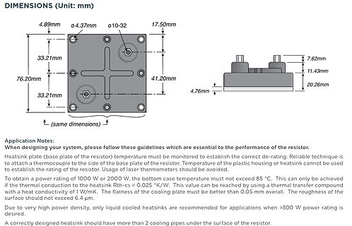
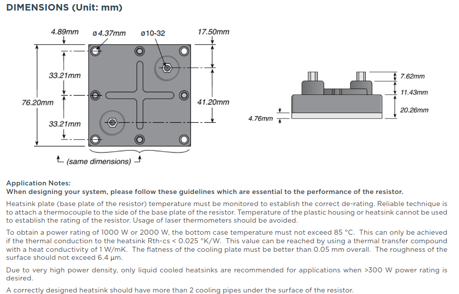
DIMENSIONS (Unit: mm)
4.89mm
ø4.37mm
ø10-32
17.50mm
33.21mm
7.62mm
76.20mm
11.43mm
41.20mm
33.21mm
4.76mm
20.26mm
Application Notes:
When designing your system, please follow these guidelines which are essential to the performance of the resistor.
Heatsink plate (base plate of the resistor) temperature must be monitored to establish the correct de-rating. Reliable technique is to attach a thermocouple to the side of the base plate of the resistor. Temperature of
Bernd schrieb im Beitrag #7732444: > Temperatur: > Tatsächlich sind es 21°C auf dem Schreibtisch, was ich mit drei versch. > Messgeräten überprüft habe. Die Sensoren melden jedoch Werte von 23,3°C > bis 28,6°C. Diese Werte sind nicht nur komplett daneben (bis zu 7,6°C),
gibt schon fast perfekt die Antwort auf die ursprüngliche Frage mit dem Bereich von 23.3 bis 28.6 bei 21 °C.

 Bild
Bild

 Bild
Bild
 Bild
Bild
 Bild
Bild
 Bild
Bild