-
PDF
dip204-4.pdf
www.lcd-module.de EADIP204-4 PINBELEGUNG Pin Symbol Level Funktion Pin Symbol Level Funktion 1 VSS L Stromversorgung 0V (GND) 10 D3 H / L DisplayData 2 VDD H Stromversorgung +5V 11 D4 (D0) H / L DisplayData 3 VEE - Kontrastspg. (ca. 0V) 12 D5 (D1) H / L DisplayData 4 RS (CS) H / L Umschaltung Befehl / Daten 13 D6 (D2) H / L DisplayData 5 R/W (SID) H / L H=Read, L=Write 14 D7 (D3) H / L DisplayData, MSB 6 E (SCLK) H Enable (fallende Flanke) 15 - - frei (siehe EA DIP122-5N) 7 D0 (SOD) H / L DisplayData, LSB 16 RES L Reset
in „RM 2,0mm Platinen Stecker“ · Markt ·
-
PDF
dip204-4_EAS.pdf
www.lcd-module.de EADIP204-4 PINBELEGUNG Pin Symbol Level Funktion Pin Symbol Level Funktion 1 VSS L Stromversorgung 0V (GND) 10 D3 H / L DisplayData 2 VDD H Stromversorgung +5V 11 D4 (D0) H / L DisplayData 3 VEE - Kontrastspg. (ca. 0V) 12 D5 (D1) H / L DisplayData 4 RS (CS) H / L Umschaltung Befehl / Daten 13 D6 (D2) H / L DisplayData 5 R/W (SID) H / L H=Read, L=Write 14 D7 (D3) H / L DisplayData, MSB 6 E (SCLK) H Enable (fallende Flanke) 15 - - frei (siehe EA DIP122-5N) 7 D0 (SOD) H / L DisplayData, LSB 16 RES L Reset
in „LCD Beschaltung“ · Mikrocontroller und Digitale Elektronik ·
-
PDF
dip204-4_EAS.pdf
www.lcd-module.de EADIP204-4 PINBELEGUNG Pin Symbol Level Funktion Pin Symbol Level Funktion 1 VSS L Stromversorgung 0V (GND) 10 D3 H / L DisplayData 2 VDD H Stromversorgung +5V 11 D4 (D0) H / L DisplayData 3 VEE - Kontrastspg. (ca. 0V) 12 D5 (D1) H / L DisplayData 4 RS (CS) H / L Umschaltung Befehl / Daten 13 D6 (D2) H / L DisplayData 5 R/W (SID) H / L H=Read, L=Write 14 D7 (D3) H / L DisplayData, MSB 6 E (SCLK) H Enable (fallende Flanke) 15 - - frei (siehe EA DIP122-5N) 7 D0 (SOD) H / L DisplayData, LSB 16 RES L Reset
in „Probleme mit LCD“ · Mikrocontroller und Digitale Elektronik ·
-
PDF
dip204-4_EAS.pdf
www.lcd-module.de EADIP204-4 PINBELEGUNG Pin Symbol Level Funktion Pin Symbol Level Funktion 1 VSS L Stromversorgung 0V (GND) 10 D3 H / L DisplayData 2 VDD H Stromversorgung +5V 11 D4 (D0) H / L DisplayData 3 VEE - Kontrastspg. (ca. 0V) 12 D5 (D1) H / L DisplayData 4 RS (CS) H / L Umschaltung Befehl / Daten 13 D6 (D2) H / L DisplayData 5 R/W (SID) H / L H=Read, L=Write 14 D7 (D3) H / L DisplayData, MSB 6 E (SCLK) H Enable (fallende Flanke) 15 - - frei (siehe EA DIP122-5N) 7 D0 (SOD) H / L DisplayData, LSB 16 RES L Reset
in „Datenblatt zu HD44780 1602 LCD Modul Display Anzeigen 2X16 Zeichen“ · Mikrocontroller und Digitale Elektronik ·
-
PDF
dip204-4.pdf
DruckfehlerundApplikationsbeispiele. PINBELEGUNG Pin Symbol Level Funktion Pin Symbol Level Funktion 1 VSS L Stromversorgung 0V 10 D3 H / L Display Data (GND) 2 VDD H Stromversorgung +5V 11 D4 (D0) H / L Display Data 3 VEE - Kontrastspannung, Eingang 12 D5 (D1) H / L Display Data 4 RS (CS) H / L Umschaltung Daten / Befehl 13 D6 (D2) H / L Display Data R/W 5 (SID) H / L H=Read, L=Write 14 D7 (D3) H / L Display Data, MSB 6 E (SCLK) H Enable (fallende Flanke) 15 - - frei (siehe EA DIP122-5N) 7 D0 (SOD) H / L Display Data, LSB 16 RES L Reset
in „LCD Display: Adressen doppelt vergeben?“ · Mikrocontroller und Digitale Elektronik ·
-
PDF
DIP203_LCD.pdf
DruckfehlerundApplikationsbeispiele. PINBELEGUNG Pin Symbo Level Funktion Pin Symbo Level Funktion 1 VSS L Stromversorgung 0V (GND) 10 D3 H / L Display Data 2 VDD H Stromversorgung +3.3V 11 D4 (D0) H / L Display Data 3 VEE - Kontrastspannung, Eingang 12 D5 (D1) H / L Display Data 4 RS (CS) H / L Umschaltung Daten / Befehl 13 D6 (D2) H / L Display Data 5 R/W H / L H=Read, L=Write 14 D7 (D3) H / L Display Data, MSB (SID) 6 E (SCLK) H Enable (fallende Flanke) 15 - - frei (siehe EA DIP122-5N) 7 D0 (SOD) H / L Display Data, LSB 16 RES L Reset
in „Temperaturmessung mit TSIC 206“ · Mikrocontroller und Digitale Elektronik ·
-
PDF
DS_DIP2034.pdf
DruckfehlerundApplikationsbeispiele. PINBELEGUNG Pin Symbo Level Funktion Pin Symbo Level Funktion 1 VSS L Stromversorgung 0V (GND) 10 D3 H / L Display Data 2 VDD H Stromversorgung +3.3V 11 D4 (D0) H / L Display Data 3 VEE - Kontrastspannung, Eingang 12 D5 (D1) H / L Display Data 4 RS (CS) H / L Umschaltung Daten / Befehl 13 D6 (D2) H / L Display Data 5 R/W H / L H=Read, L=Write 14 D7 (D3) H / L Display Data, MSB (SID) 6 E (SCLK) H Enable (fallende Flanke) 15 - - frei (siehe EA DIP122-5N) 7 D0 (SOD) H / L Display Data, LSB 16 RES L Reset
in „Ansteuerung EA DIP203-LCD“ · Mikrocontroller und Digitale Elektronik ·
-
PDF
DAVICOM.pdf
RX_CLK 47 n.b.ND 110 DUPCOL0(RECANEN) LDSPD4 57 C50100n /RST /RST 80 PW_RST# RX_ER 46 3V3 C53 100n111 VCCIK GNDO 56 GND GND 81 DGND RX_DV 45 /RST GND 112 GNDIK VCC3O 55 TP45 LED2R 82 SD15 COL 44 L21 GND TP11113 RC LDSPD3 54 83 SD14 CRS 43 FP C97 10n C55 22p GND TP98114 XI LDSPD2 53 C45 100n 84
in „Davicom DM9000 Verbindung mit Switch ADM6996i“ · Mikrocontroller und Digitale Elektronik ·
-
PDF
ATGmeo5c.pdf
0,000 –0,013 -.0005 0,051 .002 -A- 5,08) .055 (2.44) 38,1 ± 0,05 1,400 (62,00) Ø 1.003A± .002 .81 L MAX. .75 ± .04 0,077 20,60 19,1 ± 1,02 0,077A Motor L STANDARD SHAFT OPTIONS ENCODER OPTION Model Max. 1. Shaft modifications also available. See page 39. See page 53 for encoder/mounting specifications
in „Schrittmotor-Treiber Stepper Motor Pacific Scientific Powermax II“ · Mikrocontroller und Digitale Elektronik ·
-
 Bild
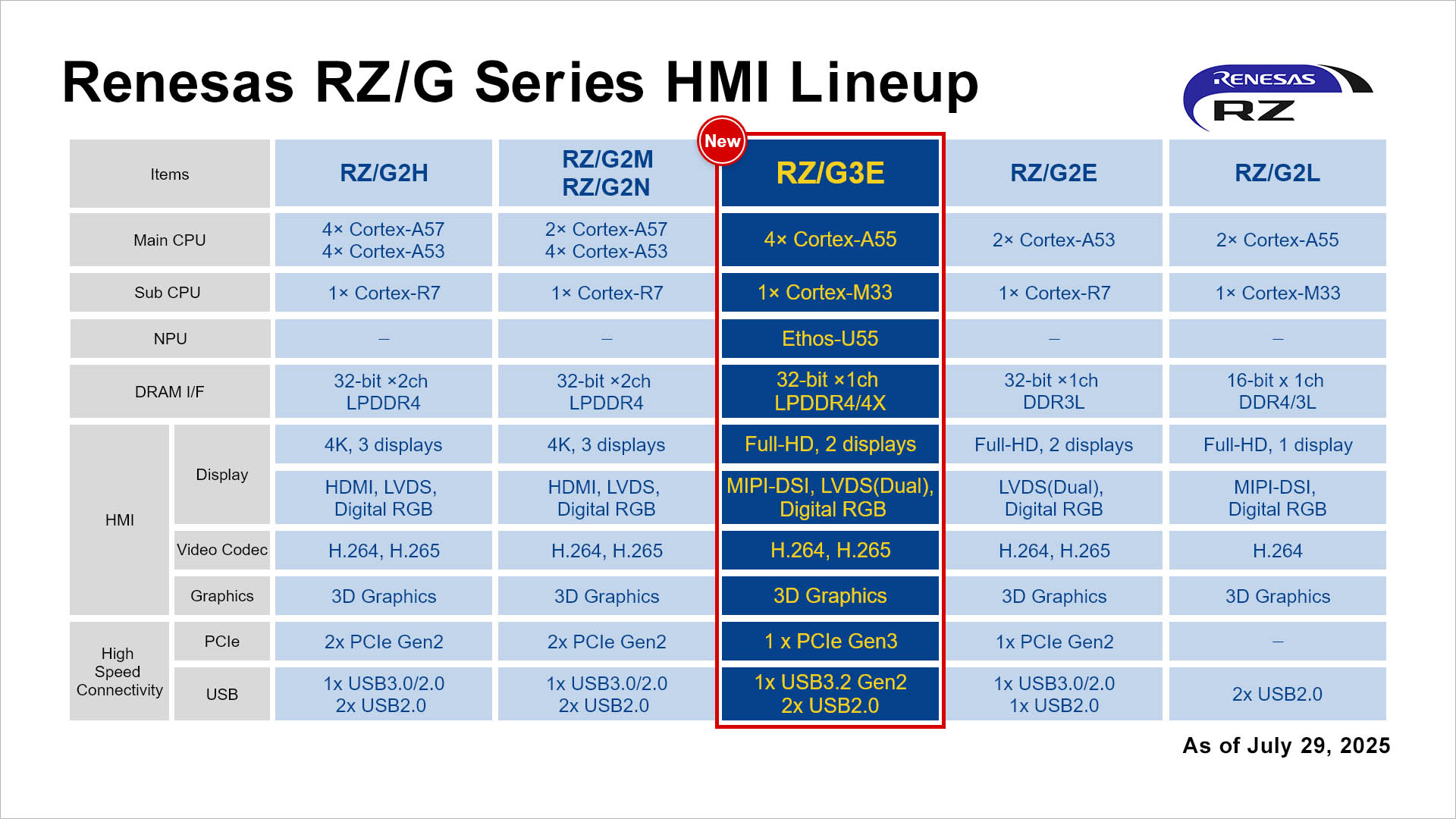
Vergleichstabelle Renesas RZ/G HMI Lineup
Renesas RZ/G Series HMI Lineup RZ/G2H RZ/G2M RZ/G3E RZ/G2E RZ/G2L Main CPU: 4x Cortex-A57, 4x Cortex-A53; 2x Cortex-A57, 4x Cortex-A53; 4x Cortex-A55; 2x Cortex-A53; 2x Cortex-A55 Sub CPU: 1x Cortex-R7; 1x Cortex-R7; 1x Cortex-M33; 1x Cortex-R7; 1x Cortex-M33 NPU: Ethos-U55 DRAM I/F: 32-bit x2ch LPDDR4; 32-bit x2ch LPDDR4; 32-bit x1ch LPDDR4/4X; 32-bit x1ch DDR3L; 16-bit x1ch DDR4/3L Display: Full-HD, 2 displays; HDMI, LVDS, Digital RGB; MIPI-DSI, LVDS(Dual), Digital RGB; LVDS(Dual), Digital RGB; Full-HD, 1 display Video Codec: H.264, H.265 Graphics: 3D Graphics
in „Renesas-MPU mit AI-Beschleuniger, Zephyr 4.2, NXP MCX E und Lesestoff“ · Mikrocontroller und Digitale Elektronik · · Diagramme
-
PDF
SSD1325_Salomon.pdf
edge of E signal. Table 7: Control pins of 6800 interface Function E R/W# CS# D/C# Write command ↓ L L L Read status ↓ H L L Write data ↓ L L H Read data ↓ H L H (1)e ↓ stands for falling edge of signal H stands for HIGH in signal L stands for LOW in signal In order to match the operating frequency
in „OLED VGY12864Z-S005 über LPT Port ansteuern“ · Mikrocontroller und Digitale Elektronik ·
-
PDF
DS_TTL-232R_CABLES_V201.pdf
000054 TTL-232R TTL TO USB SERIAL CONVERTER RANGE OF CABLES Datasheet Version 2.01 Clearance No.: FTDI# 53 1 Description The TTL-232R cables are a family of USB to TTL serial UART converter cables incorporating FTDI’s FT232RQ USB to Serial UART interface IC device which handles all the USB signalling and
-
Datei
ca_crt.txt
Number: a2:f6:ff:cb:5b:16:91:1b Signature Algorithm: sha256WithRSAEncryption Issuer: C = IT, ST = BZ, L = Truden, O = My Org, emailAddress = xxxx.xxxx@gmail.com Validity Not Before: Aug 16 07:28:02 2019 GMT Not After : Aug 13 07:28:02 2029 GMT Subject: C = IT, ST = BZ, L = Truden, O = My Org, emailAddress
in „Openvpn Server Umzug Client kann sich nicht verbinden“ · PC Hard- und Software ·
-
PDF
translate.pdf
7E FE 6D F0 6D Keyboard Equal Sign 07 86 UNASSIGNED UNASSIGNED UNASSIGNED UNASSIGNED Keyboard Int'l 1 ろ 07 87 73 F3 51 F0 51 (Ro) Keyboard Intl'2 かかかか ひひひか 07 88 70 F0 13 F0 13 ロロロ字 (Katakana/Hiragana) Keyboard Int'l 2 ¥ 07 89 7D FD 6A F0 6A (Yen) Keyboard Int'l 4 前前前 変変 (次前前 ) 07 8A 79 F9 64 F0 64
in „USB Tastatur Scancode“ · Mikrocontroller und Digitale Elektronik ·
-
PDF
CF_Serie.pdf
entsprechend der kleinstwertigsten 8 Digit BCD Volumen Volumen Displayanzeige. Mögliche Werte sind: 1m , 100l, 10l, 1l. 0Ch 13/14/15/16 WWh WWh WWh WWh DIF VIF Wert Die Leistung wird mit 0,1kW Auflösung für < 100MW und 1kW Auflösung für > 100MW 6 Digit BCD Leistung Leistung übertragen. Im Fehlerfall wird DIF
in „Wärmezähler über optische M-Bus-Schnittstelle auslesen“ · Haus & Smart Home ·
-
PDF
MGA52543.pdf
input pin and 47nH B -2 42 ( the adjacent ground pad to create 1000pF S Input RL a shunt C-series L matching L -6 network will realize an improve- 12nH N U-10 ment in noise figure of several +5V E tenths of a dB. A lower value for R-14 Figure 11. Schematic of 900 MHz Circuit. U L1 may be needed depending on T-18 the actual length of the input line O d-22 between pin 1 and L1 as well as L1 12nH LL1608-FH12N a the value of the shunt C. U-26 L2 3.3nH LL2012-F3N3 P Output RL I-30 For frequencies above 3.0 GHz, RFC 47nH LL1608-FH47N 0.4 0.6 0.8 1.0 1.2 1.4 FREQUENCY (GHz) the
in „Wie ist ein MMIC intern aufgebaut?“ · HF, Funk und Felder ·
-
PDF
vestel_17ips71-r3_sch.pdf
VCC_LED D +12VCC S46 5 D C84 C83 6 10u 10u +24 50V 50V LED DRIVER SINK MOSFET OPTION 7 CHANNEL OPTIONS S53 8 LED4_S LED2_S LED1 LED1_S LED2 S52 LED2_S Q18 Q19 FQD7N10L VCC_LED FQD7N10L VCC_LED S51 R110 LED3 LED3_S R299 100R 100R R87 LED4 S50 LED4_S R298 k 0 LED4 1 LED2 E 1 S49 E LED1 LED2 S48 LED3 LED4 S47
in „TV PSU 17IPS71 Sekundärseitig Kurzschluss?“ · Analoge Elektronik und Schaltungstechnik ·
-
PDF
vestel_17ips71-r3_sch.pdf
VCC_LED D +12VCC S46 5 D C84 C83 6 10u 10u +24 50V 50V LED DRIVER SINK MOSFET OPTION 7 CHANNEL OPTIONS S53 8 LED4_S LED2_S LED1 LED1_S LED2 S52 LED2_S Q18 Q19 FQD7N10L VCC_LED FQD7N10L VCC_LED S51 R110 LED3 LED3_S R299 100R 100R R87 LED4 S50 LED4_S R298 k 0 LED4 1 LED2 E 1 S49 E LED1 LED2 S48 LED3 LED4 S47
in „L40f278x3cw-3DU Vestel 171ps71“ · Analoge Elektronik und Schaltungstechnik ·
-
PDF
MRF272L.pdf
given output power, voltage and frequency. Figure 10. Series Equivalent Input/Output Impedance MRF275L MOTOROLA WIRELESS SEMICONDUCTOR 5.2–276 SOLUTIONS – RF AND IF DEVICE DATA RFC1 R1 +28 Vdc BIAS + C4 C5 C10 C11 L4 R2 C1 L2 L3 C9 RF INPUT RF OUTPUT L1 C2 C3 C6 C7 C8 DUT C1, C2, C8 Arco 463 or Equivalent
-
PDF
ADNS-2700.pdf
e L o F O r 1 0 s f C 2 U L n o 1 F e E F o t u f i _ 9 0 u B l e c V C 2 f g i s t n L R M l h pa h R R m p e g V V 2 2 ) e o el C / n d d t L μ p e a i R C 10 U n n e W e p p a P R R 1 l u D e r i Q R
in „USB Maus mit USART auslesen“ · Mikrocontroller und Digitale Elektronik ·
-
PDF
usr_scm_stm32com-a2-1.pdf
STMPS2141STR R / V V V 2V C R 4 5 1 0 U402 + + 1+ ] PC9 4 VIN VOUT 3 * B3 B2 1 1 EN FADLT_N 4 A3 VBUS PUP B1 L400 1 2 U400P . N ID PD1 C2 4 L 39 40 B G PD2 X406C BLM21A121 L B 45 VCCE/I1 GNDE/I1 50 , D2 A2 62 VCCE/I2 GNDE/I2 25 5 2 GND DZ ZX62-AB-5PA VCCE/I3 GNDE 1 [ PA9 1 9 VCCA1 GNDA1 7 A PA11 D3 DM_OUT DM_IN
in „STM32-comStick USB-Bootloader“ · Mikrocontroller und Digitale Elektronik ·
-
PDF
HY1403-HOOYI.pdf
Information TO-252-2L mm SYMBOL MIN NOM MAX A 2.20 2.30 2.38 A1 0.00 - 0.10 A2 0.97 1.07 1.17 b 0.72 0.78 0.85 b1 0.71 0.76 0.81 b3 5.23 5.33 5.46 c 0.47 0.53 0.58 c1 0.46 0.51 0.56 D 6.00 6.10 6.20 D1 5.30REF E 6.50 6.60
in „Alternative zu beschädigtem MOSFET?“ · Analoge Elektronik und Schaltungstechnik ·
-
PDF
HD61202U.pdf
V1L V EE2 8 73 VEE1 Y64 9 72 Y1 Y63 10 71 Y2 Y62 11 70 Y3 Y61 12 69 Y4 Y60 13 68 Y5 Y59 14 67 Y6 Y58 15 HD61202UFS 66 Y7 (FP-100A) Y57 16 65 Y8 Y56 17 64 Y9 Y55 18 63 Y10 Y54 19 62 Y11 Y53 20 61 Y12 Y52
in „seltsames Grafik Display verhalten“ · Mikrocontroller und Digitale Elektronik ·
-
PDF
2012_02-RIAA.pdf
5 235V K4 R26 3 IC7A 7 0dB R47 2000R 220n R32 R33 R34 IC7B 47R LLL_P_L 220n 220n k 6 R36 R37 2400R R28 R29 R30 R31 0 4 6 R R R27 C22 2 R35 2 3 6 6 0 0 8 1 3 3 1 1 10k +5dB 2n2 C26 RE2B R38 R39 R48 K5 1000u 0 0 35V JP1 4 7 47R PHONO+_L PHONO-_L 1 2 +10dB 3 4 R40 R41 5 6
in „Empfehlung für Phono-Vorverstärker-Schaltplan?“ · Analoge Elektronik und Schaltungstechnik ·
-
PDF
42_0426_0209_DE.pdf
abgesichert werden. Im Notstrom-Betrieb werden nur die Notstrom-Kreise durch die Schütze K1 und K2 3- polig (L1, L2 und L3) vom Netz getrennt. Das restliche Hausnetz ist in diesem Fall nicht versorgt 5 Folgende Punkte sind bei der Verkabelung zu beachten: - Die Hauptkontakte der Schütze K1 und K2 müssen zwischen
in „Hybrid Wechselrichter Huawei SUN2000“ · Haus & Smart Home ·
-
PDF
HD44100_Spaltentreiber.pdf
Y10 21 60 Y71 Y9 22 59 Y72 Y8 23 58 Y73 Y7 24 57 Y74 Y6 25 56 Y75 Y5 26 55 Y76 Y4 27 54 Y77 Y3 28 53 Y78 Y2 29 52 Y79 Y1 Y80 30 51 3 3 3 3 3 3 3 3 3 4 4 4 4 4 4 4 4 4 4 5 E 1 2 3 4 D 1 C L 2 I C C C C C C C VE V V V V N L N H L D D N M N VC N N N N G C S C (Top view) 2 3 3 3 3 3 3 3 3 3 3 4 4 4 4 4
in „HD44780 und HD44100 Schaltung“ · Mikrocontroller und Digitale Elektronik ·
-
PDF
MCP1703_MIC.pdf
&VYNR,3PPUWNR0L,.LFURZPL:\WFY0R0XULYURYUURNGURO\,PV,G\0R1L,.LF\WFR60U,\8\,LN\VWRXV,LNUZRLNR GNN0+22:::<&\,PV,G\0<,V&20L,.LF\WF D D1 E H L 1 2 N b b1 b1 e e1 E1 A C 3W\NYO[44[O)()J6 '\&UWY\VWR4\&\NY O[5 OD7 53&8UPRV8R4ULZY5
in „Was ist das für ein IC“ · Mikrocontroller und Digitale Elektronik ·
-
PDF
adb87.pdf
EC-Servomotoren EC-Servomotoren - 250 W bis 650 W Typen DB87 - Größe S, M, L Anschlußbelegung PIN Farbe Funktion 1 rot +5V 2 schwarz GND 3 blau H1 Hall 4 weiß H2 5 grün H3 6 gelb A 7 braun A\ 8 grau B Encoder 9 grau/rosa B\ 10 violet I 11 rot/blau I\ PIN Farbe Leistung 1 weiß
in „Suche gute Freilaufdioden für BLDC-Endstufe“ · Mikrocontroller und Digitale Elektronik ·
-
Datei
Eeprom_2.asm
53h ret z call l0302 jr l1a93 l1aa2: xor a ld (0d189h),a ret l1aa7: ld a,08h ld (0d173h),a ld a,(0d184h) add a,30h call l0b20 call l0ad2 cp 2eh jr z,l1ac7 cp 53h jr z,l1ad8 cp 48h ret z call l0302 jr l1aa7
in „Hilfe bei Z80 Opcodes“ · Mikrocontroller und Digitale Elektronik ·
-
PDF
mb01d.pdf
A A A G G G G F F L L Filter und Schutzscheiben 1. für elektronische Displays Entspiegelung: keine l ¡ l l Diffuse Streuung ¡ l ¡ ¡ l l ¡ ¡ ¡ ¡ l l l l l Optisch Abschirmung l l l l l l Erhöhte Kratzfestigkeit l l l l l l l l l l l l l l 2. für Bildröhren l ¡ l ¡ ¡ ¡ 3. für IR-Anwendungen ¡ l ¡ 4. für Laser-Scanner l l 5. für Großflächen-Anzeigen ¡ l l ¡ ¡ l l l l Streufilter ¡ l Platten (für Modellbau, Werbung) ¡ l ¡
in „Filterglas“ · Markt ·
-
PDF
schiebereg.pdf
register with output latches; 3-state FUNCTION TABLE INPUTS OUTPUTS FUNCTON SHCP ST CP OE MR DS Q 7 N X X L L X L NC a LOW level on MR only affects the shift registers X ↑ L L X L L empty shift register loaded into storage register X X H L X L Z shift register clear. Parallel outputs in high-impedance OFF-state
in „wie steuer ich nen sn7447 mit avr an??“ · Mikrocontroller und Digitale Elektronik ·
-
PDF
74HC_HCT595_CNV_3.pdf
register with output latches; 3-state FUNCTION TABLE INPUTS OUTPUTS FUNCTON SHCP ST CP OE MR DS Q 7 N X X L L X L NC a LOW level on MR only affects the shift registers X ↑ L L X L L empty shift register loaded into storage register X X H L X L Z shift register clear. Parallel outputs in high-impedance OFF-state
in „LCD DEM20485 in gerade Zeile springen (c't-Bot)“ · Mikrocontroller und Digitale Elektronik ·
-
PDF
S9132_datasheet.pdf
(10-bit) l Moving object detection (FA inspection equipment, l Low power consumption amusement machines) l Digital video output l 3D measurement (FA inspection equipment, l 10-bit/8-bit switchable ADC medical measurement
in „Belichtungssteuerung bei S9132“ · Mikrocontroller und Digitale Elektronik ·
-
PDF
15_viver_4_400_4400ec_bt2ns6r916m.pdf
jest prądem jednofazowym. Parametry w punkcie pracy Parametry techniczne Wartości mocy akustycznej L WA [dB(A)] 3 Przepływ 900 m /h Hz Σ 63 125 250 500 1k 2k 4k 8k Ciśnienie statyczne 420 Pa Wlot - L 69 53 60 61 64 62 60 55 45 WA5 Pobór mocy 246 W Wylot - WA6 70 53 62 65 64 65 62 55 45 Napięcie nominalne ~1 230 V Poziom ciśnienia akustycznego L [dB(A)] Pobór prądu 1.12 A PA Odległość od wentylatora [m] L [dB(A)] Częstotliwość nominalna 50 Hz PA Prędkość obrotowa 1368 min -1 10,0 39 Prędkość przepływu 1.99 m/s 4,0 47 SFP 985 W/(m /s) 1,0 59
in „0-10V Steuerspannung für EC-Ventilatoren“ · Mikrocontroller und Digitale Elektronik ·
-
PDF
Metrawatt-MA_5D.pdf
D 3 RIl8 83· V49 A3 C26 B4 ; C3 R129 C4 . B2 Cl7 B5 R25 V50 51 C2B A4 R26,27.28 Al Rl30,131 C5 V5Z.53 AI' C29 Bl R29,30 A4 R132 04 V54 85 C30 C4 R31.32,33 Al R133 A3 VS5.56 C5 C3l Al R34..38 01 R134.l)S B7C3 VS7 A1I2 R39 40 B4 V58 At C3l B4 R41 C4 R137 81 VS9 Bl C33 B5 R42,43 B5 Rna B112 V60 04 C34 35
in „S: DMM mit dB-Anzeige“ · Markt ·
-
PDF
Metrawatt-MA_5D.pdf
D 3 RIl8 83· V49 A3 C26 B4 ; C3 R129 C4 . B2 Cl7 B5 R25 V50 51 C2B A4 R26,27.28 Al Rl30,131 C5 V5Z.53 AI' C29 Bl R29,30 A4 R132 04 V54 85 C30 C4 R31.32,33 Al R133 A3 VS5.56 C5 C3l Al R34..38 01 R134.l)S B7C3 VS7 A1I2 R39 40 B4 V58 At C3l B4 R41 C4 R137 81 VS9 Bl C33 B5 R42,43 B5 Rna B112 V60 04 C34 35
in „Metrawatt MA5D Abgleichanleitung A DC Bereich“ · Analoge Elektronik und Schaltungstechnik ·
-
PDF
stepping_motor_Mdrive__OM-MD_V06.28.2002__e.pdf
41.28) (38.10) 0.810 ± .030 4 x Ø 0.205 (5.21) (20.57 ±.76) ±.010 (.25) HOLES 0.060 EQ. SPACED ON A (1.53) 2.625 (66.68) DBC. 0.590 (14.86) 0.230 ± .005 (73.84) (5.84 ± .127 ) 1.860 SQ. (47.24 SQ.) 0.2500 (6.35) Ø 0.2495 (6.34) L MAX Ø 15.0±±.5) (56.39 SQ.) (Ø 38 LMAX2 Standard Rotary L Encoder/Control Knob
in „Alter Stepper-Treiber über ISP an USB parametrieren“ · Mikrocontroller und Digitale Elektronik ·
-
PDF
page_883.pdf
rührt K auf L Ja 1000 **) 1000 – K<L 1 daher, dass die wirkliche Spannung gegen Erde vom Iso- vergrößern K<L ) Leiter-Erde-Isolationspegel für ungeerdete oder impe- lationswiderstand und vom kapazitiven Blindwiderstand
in „Layoutprüfung: Dimmer“ · Platinen ·
-
PDF
KOMMPROT.pdf
L 1 Byte ASCII Telemetrie-Offset-Zeit n x 250ms/Telemetrie- Senderkennung L 1 Byte 0x00 aktuelle Telemetrie-Offset-Zeit/Senderkennung M 6 Byte BCD Datum/Uhrzeit TTMMJJSSMMSS Dieses Telegramm wird auch
in „RS-232 Daten auslesen und verarbeiten“ · PC Hard- und Software ·
-
PDF
ver968de.pdf
KW cos v 0.82 S1 4.0 KW cos v 0.82 1410 min1 50 Hz 1410 min-1 50 Hz IP 54 Iso. KI F IP 54 Iso. KI F L1 L2 L3 L1 L2 L3 I ULN LN ULN LN V1 U2 V1 U2 V2 U1 V2 U1 W2 W2 W2 W1 U LN= √3 • U W ILN= IW U LN= U W LN = √3 • W L1 L2 L3 L1 L2 L3 LN U LN LN ULN U1 V1 W1 U1 V1 W1 W2 U2 V2 W2 U2 V2 Mit seiner Spannungsangabe
in „Drehstromkompressor an 230V via FU“ · Analoge Elektronik und Schaltungstechnik ·
-
PDF
grundig_chassis_t5_19_22vle2000t_22-2010t_22-2940t_22-2942t_19hd_br_wp_cba_16-2941tc_19-2940t.pdf
D711 T 133 18 L910 T 33 14 R452 T 37 90 R740 T 94 31 R922 T 27 28 C438 T 29 62 C760 T 14 23 D712 T 103 38 R456 T 22 86 R741 T 93 29 R923 T 17 53 L911 T 21 17 C440 T 52 82 C762 T 100 47 D713 T 103 32 L912 T 28 25 R457 T 20 94 R743 T 155 26 R924 T 13 50 C445 T 53 82 C763 T 16 26 D714 T 133 27 L914 T 57 14 R458 T 22 89 R744 T 149 26 R925 T 17 51 C446 T 46 49 C764 T 103 46 R459 T 48 82 R745 T 153 26 R926 T 24 4 C451 T 45 53 C765 T 14 26 D715 T 131 26 L917 T 31
in „Grundig Fernseher defekt“ · Analoge Elektronik und Schaltungstechnik ·
-
PDF
Amidon_-18_-26_Material__SIV.pdf
characteristics line filter applications. 1 SIV Ringkern-Material 18 Type A nH/N 2 OD (mm) ID (mm) Ht (mm) L T16-18 9,5 4,06 1,98 1,52 T20-18 13,0 5,08 2,24 1,78 T25-18 17,0 6,48 3,05 2,44 T30-18 22,0 7,80 3,84 3,25 T37-18 19,0 9,53 5,21 3,25 T44-18 25,5 11,2 5,82 4,04 T50-18 24,0 12,7 7,70 4,83 T50-18B 32,0
in „MC33063 und Spule“ · Analoge Elektronik und Schaltungstechnik ·
-
PDF
18__26_Material_1.pdf
characteristics line filter applications. 1 SIV Ringkern-Material 18 Type A nH/N 2 OD (mm) ID (mm) Ht (mm) L T16-18 9,5 4,06 1,98 1,52 T20-18 13,0 5,08 2,24 1,78 T25-18 17,0 6,48 3,05 2,44 T30-18 22,0 7,80 3,84 3,25 T37-18 19,0 9,53 5,21 3,25 T44-18 25,5 11,2 5,82 4,04 T50-18 24,0 12,7 7,70 4,83 T50-18B 32,0
-
PDF
IP113A_ReferenceDesign.pdf
of 7 5 4 3 2 1 E D O Y1 _ X2 OSCI E E C1 25MHZ C2 S 15p 15p D X D S F D X _X _ _F C3 C4 D D 0.01u L L 0.01u E D O CRYSTALL _ E E S D X S F C C I C X X C L A C S C _ F D S S D O X D D D L L IP113A/LQFP 8 7 6 5 4 3 2 1 0 9 8 7 U1 4 4 4 4 4 4 4 4 4 3 3 3 I C CC A C D D CX C E X DVCC V NS S V G G S V O
in „Umsetzer Ethernet Glasfaser“ · Mikrocontroller und Digitale Elektronik ·
-
PDF
Nema23PowermaxII.pdf
Inductance l l Current/ Phase Thermal Rotor Motor l e o (2 phases on) Phase Resistance Detent Resistance Inertia Model Number r r n oz-in (Nm) (ohms) (mH) Torque oz-in-S2 Weight P S U ±10% (amps DC) ±10% Typical
in „Schittmotor Pacific Scientific Steckverbinder“ · Mikrocontroller und Digitale Elektronik ·
-
 Bild
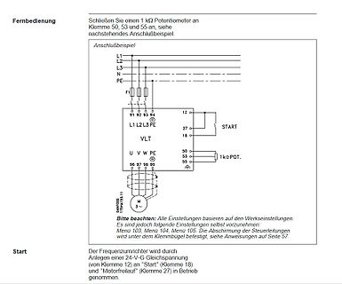
Schaltplan eines Frequenzumrichters mit Anschlussbeispiel
Fernbedienung Schließen Sie einen 1 kΩ Potentiometer an, Klemme 50, 53 und 55 an, siehe nachstehendes Anschlußbeispiel Anschlußbeispiel L1 L2 L3 N PE 91 92 93 94 L1 L2 L3 PE VLT 12, 27, 18, 50, 53, 55, 1kΩ POT. START U V W PE 96 97 98 95 DANFOSS 17SHA153.11 M 3~ Bitte beachten
in „Danfoss FU VLT 3006 Tod“ · Analoge Elektronik und Schaltungstechnik · · Schaltpläne
-
PDF
FAN5624.pdf
FAN5624 / FAN5626 • Rev. 1.0.3 5 F A 5 Typical Performance Characteristics 2 2 / A N 6 4 / A N 5 2 6 — L n a L E Figure 8. Efficiency vs. Input VolFage whereFigure 9. Dropout Voltage vs. Input Voltage D v r s i h S n l - W e D g a l t Figure 10. Current Match of Channels vs. InFigure 11. Load Regulation
in „LED Treiberstufe ansteuern“ · Mikrocontroller und Digitale Elektronik ·
-
PDF
FAN5624.pdf
FAN5624 / FAN5626 • Rev. 1.0.3 5 F A 5 Typical Performance Characteristics 2 2 / A N 6 4 / A N 5 2 6 — L n a L E Figure 8. Efficiency vs. Input VolFage whereFigure 9. Dropout Voltage vs. Input Voltage D v r s i h S n l - W e D g a l t Figure 10. Current Match of Channels vs. InFigure 11. Load Regulation
in „LED-Treiber Ansteuern Software“ · Mikrocontroller und Digitale Elektronik ·
-
PDF
Crimp.pdf
/ Buchse (4 microinches) auf Rolle zu 10.000 Stück 0,8 µm 10 strips of 25 pieces in a box 20-24 P7L-K176 Pin / Stift F1089 (31 microinches) 10 Streifen á 25 Stück in einer Schachtel 0,8 µm 10 strips of 25 pieces in a box 20-24 S7L-K176 Socket / Buchse F1089 (31 microinches) 10 Streifen á 25 Stück in
in „D-SUB Stift mit Crimpkontakt“ · Mechanik, Gehäuse, Werkzeug ·
-
PDF
p6smb6.pdf
47.8 5 53.2 56 58.8 1 77 7.8 0.103 365 P6SMB62AT3G 62A 53 5 58.9 62 65.1 1 85 7.1 0.104 335 P6SMB68AT3G 68A 58.1 5 64.6 68 71.4 1 92 6.5 0.104 305 P6SMB75AT3G 75A 64.1 5 71.3 75.05 78.8 1 103 5.8 0.105 280 P6SMB82AT3G
in „was ist das für ein Bauteil“ · Analoge Elektronik und Schaltungstechnik ·