0.010 0.018 L1 θ 0° 8° 0° 8° b C SOT23-5 Dimensions Dimensions Symbol In Millimeters In Inches Min Max Min Max A 1.040 1.350 0.042 0.055 A1 0.040 0.150 0.002 0.006 A2 1.000 1.200 0.041 0.049 b 0.380 0.480 0.015 0.020 c 0.110 0.210 0.004 0.009 D 2.720 3.120 0.111 0.127 E 1.400 1.800 0.057 0.073 E1 2.600
0.010 0.018 θ 0° 8° 0° 8° L1 b C SOT23-5 Dimensions Dimensions Symbol In Millimeters In Inches Min Max Min Max A 1.040 1.350 0.042 0.055 A1 0.040 0.150 0.002 0.006 A2 1.000 1.200 0.041 0.049 b 0.380 0.480 0.015 0.020 c 0.110 0.210 0.004 0.009 D 2.720 3.120 0.111 0.127 E 1.400 1.800 0.057 0.073 E1 2.600
Unterteilungs- und Zähl-Elektronik unter- teilt die sinusförmigen Eingangssignale Eingangsfrequenz (max.) 500 kHz 33 kHz – bis zu 4096fach. Eine Treiber-Software gehört zum Lieferumfang. Kabellänge (max.) 60 m 10 m Signal-Unterteilung (Signalperiode:Messschritt) bis zu 4096fach Datenregister für 48 bit
SUBPART J APPLICABLE AT THE DATE OF MANUFACTURE. COMPLY WITH DHHS RULE 21 CFR CAMBRIDGE, CB5 9PB. MAX WARNING: THIS APPLIANCE MUST BE EARTHED. Amplifier Board L924 Contents Circuit description Component overlay Parts list Circuit diagrams The line ‘NFB’ provides for a portion of the negative feedback
place.The compressors will withstand storage temperatures down to -35°C. Condensing temperatures: Max. 60°C at stable conditions and max. 70°C at peak load. Ambient temperatures: Min. -10°C, max. 55°C The BD compressor concept includes an electronic unit which features overload protection, battery protection
53924) map I (124) esp_image: segment 1: paddr=0002d2cc vaddr=3ffb0000 size=02d4ch ( 11596) load I (127) esp_image: segment 2: paddr=00030020 vaddr=400d0020 size=22094h (139412) map I (165) esp_image: segment 3: paddr=000520bc vaddr=3ffb2d4c size=005d4h ( 1492) load I (166) esp_image: segment 4: paddr
cpu_start: ESP-IDF: v5.2.2 I (246) cpu_start: Min chip rev: v0.0 I (251) cpu_start: Max chip rev: v3.99 I (256) cpu_start: Chip rev: v3.1 I (261) heap_init: Initializing. RAM available for dynamic allocation: I (268) heap_init: At 3FFAE6E0 len 00001920 (6 KiB): DRAM I
Max M. schrieb im Beitrag #7684883: > Nun selbst PTFE schafft über 100kV/mm Dass kein Kabelhersteller das so verwendet sollte dir zu denken geben.
Max M. schrieb im Beitrag #7685722: > Danke ist interessant; der min biegeradius ist etwas schmerzhaft. Ja, 127mm. Dickes Polyethylen ist halt starr, kann man mit den PE Speedpiperöhrchen der Glasfaserverleger
die Linux-Version hat > einen guten Pseudozufallsgenerator hinter rand(). Ja, ok. Hier ist RAND_MAX gleich INT_MAX, ja, vermutlich ist es hier gar nicht so schlecht. -- Der Code von Gerald hat noch einen Fehler drin, wenn man rand() nimmt. Statt UINT32_MAX sollte man RAND_MAX nehmen, und statt
Daniel A. schrieb im Beitrag #7683172: > Ja, ok. Hier ist RAND_MAX gleich INT_MAX, ja, vermutlich ist es hier gar > nicht so schlecht. Intern wird wohl noch mit mehr Bits gearbeitet. Aus der man-Page: "Die Periode dieses Zufallszahlengenerators ist sehr groß,
behavior. The 5.3 Write-heavy Applications S6 model used in our experiments has 32 GB of capacity and a max- Apps excluded from this study may still issue exceptionally high imum two year warranty [122]. According to our measurements, the minimum volume of writes required to consume 10% of the S6’s write
Fields (addresses 64 to 94) VENDOR SPECIFIC ID FIELDS Read-only Vendor specific data, read only 96-127 32 128-511 384 Reserved 512-n Vendor specific ____________________________________________________________________________________________________ September 14, 2000 Page 32 Small Form-factor Pluggable
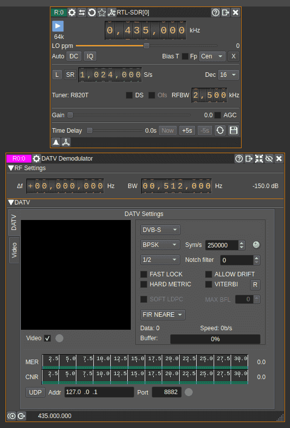
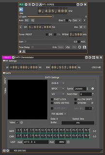
Settings DVB-S BPSK Sym/s 250000 Notch filter 0 1/2 FAST LOCK ALLOW DRIFT HARD METRIC VITERBI R SOFT LDPC MAX BFL 0 Video Buffer: 0b/s 0% MER CNR UDP Addr 127.0.0.1 Port 8882 435.000.000
ambiAnt, T , and internal leadframe temperA ures, T , provided that the Maximum Junction Temperature, J(max), is not exceeded. 21G = 0.1 mT. 3R forms an RC circuit via the FILTER pin. F(INT) COMMON THERMAL CHARACTERISTICS 1 Min. Typ. Max. Units Operating Internal Leadframe Temperature TA E range –40 – 85
AAA Energizer Max (Singapore) AAA Energizer Max aus IR-FB gebr. MHD 12-2030 MHD 12-2030 Kauf 10-2020 Kauf 10-2020 17. Oktober 2021 15. Mai 2024 Entladung mit: 30 mA Entladung mit: 30 mA mAh max: 1197 mAh max: 1100 Time
= 400 V DC or V AC, T = 120 °C (typ.), R = ±25 % max R ref R B750 123 245 4.0 4 25 13 X X B59750B0120A070 B770 64 127 2.8 3.0 70 45 X X B59770B0120A070 C751 87 173 4.0 3.5 50 26 X X B59751C0120A070 C752 69 137 4.0 3.5 80 42 X X B59752C0120A070 C753 56
sec)(meters) Length limiting faTyp.number limiting factor I C 400k 2 w iring capacitance 20 400pF max Speed of various connectivity methods (bits/sec) I Cw ith buffer 400k 100 propagation delays any no limit I Chigh speed 3.4M 0.5 w iring capacitance 5 100pF max CAN 1 wire 33k 100 total capacitance
Figure 20-10. Single-Slope Pulse Width Modulation Period (T) CMPn=BOTTOM CMPn=TOP "update" "match" MAX TOP CNT CMPn BOTTOM Output WOn The TCA.PER register defines the PWM resolution. The minimum resolution is 2 bits (TCA.PER=0x0003), and the maximum resolution is 16 bits (TCA.PER=MAX). The following
-Treiber-Elektronik die Sende-Stufe mit einer Art Tristate-Modus abschalten können. Beim bekannten MAX232 geht das leider nicht, dafür aber bei den Typen ICL3321 und MAX242. Tx: cmd arg0 arg1 ... argX/n Rx: cmd arg0 arg1 ... argX/n Beide verfügen über Low-Power-Shut- replyline1/n down-Modi, die sogar
Select Wait time (Write/Read) 10 - ns i VCCIO=1.8V VCCIO=2.5V VCCIO=3.3V PARAMETER DESCRIPTION Min Max Min Max Min Max UNIT D T SPI clock period 33.3 - 33.3 - 33.3 - Tsclkl SPI clock low duration 13 - 13 - 13 - T sclkh SPI clock high duration 13 - 13 - 13 - D T sac SPI access time 4 - 3.5 - 3 - T isu
are at T = 25°C. V is from7V to 80V, unless noted. (Note 3) A IN SYMBOL PARAMETER CONDITIONS MIN TYP MAX UNITS General V Supply Voltage l 7 80 V IN IIN Supply Current VIN 48V, Normal Operation Mode l 1.2 1.7 mA VIN= 12V, Shutdown Mode l 120 300 µA + + – ISENSE SENSE Input Current VIN SENSE , SENSE = 48V
//www.thermalcutoff.com/en/document/gfile.php?fn=sw-1-series Aufschrift laut Foto oben: S.W.C. SW-127T 250V 10A In der Tabelle die 6. von unten: SW-127T 184℃ 184℃ +0℃/-6℃ 169℃ 220℃ u.a. "TUV gepruft" Achtung beim Einlöten, sonst ist die Übertemperatursicherung gleich kaputt. Mit einer Zange
gibt aber auch >20 € Datenblatt: https://docs.rs-online.com/7d49/A700000007842085.pdf Temperatur max. +150°C Öffnungstemperatur 120°C Schließtemperatur 105°C Also der heizt bis 120° erreicht sind, schaltet dann ab bis durch Abkühlen 105° unterschritten werden. Die Temperatursicherung ist übrigens
einen RC-Tiefpass (10k / 10nF)her und speisen ihn mit einer Sinusspannung bei seiner Grenzfrequenz (U max= 1V / f = 1591 Hz). Dann simulieren wir von 0….4ms und lassen uns die Eingangsspannung anzeigen. Nun holen wir uns zusätzlich über „rechten Mausklick auf das Diagramm / Add Plot Pane“ insgesamt 3 zusätzliche
@Max I. (powermeter) @Hmmm (hmmm) Ist das nicht ein Nebenkriegsschauplatz? Wenn .70 nicht geht, .74 oder .80 aber doch, dann hat es nichts mit dem Range .150 bis .199 zu tun.
Max I. schrieb im Beitrag #7633154: > Nein. Lustig. Habe ich lange so gemacht. Ne 7490 mit FritzOS 7.x Max I. schrieb im Beitrag #7633154: > Definitiv nein. Komisch. Mach ich aktuell so. Mikrotik
ITEM STANDARD VALUE UNIT STANDARD VALUE ITEM SYMBOL UNIT Module dimension 26.7 x 19.26 x 1.65 MIN. MAX. Viewing area 23.938 x 12.058 Supply voltage V 0 4 Active area 21.738 x 10.858 for logic1)(2) DD Dot size 0.148 x 0.148 mm V Supply voltage V CC 0 15 Dot pitch 0.17 x 0.17 for display1)(2) Mounting
PAGE7 (COM56-COM63) Page 7 PAGE7 (COM 7-COM0) SEG0 ---------------------------------------------SEG127 Column re-mappingSEG127 ---------------------------------------------SEG0 When one data byte is written into GDDRAM, all the rows image data of the same page of the current column are filled (i.e. the
Active Area / Memory Mapping & Pixel Construction 1.4 Mechanical Drawing 1.5 Pin Definition 2 Abso u e Max mum Ra ng ti s 3. Optics & l E ec trca Cha ac e t ris c s 3.1 Optics Characteristics 3.2 DC Characteristics 3.3 AC Characteristics 3.3.1 I2C Interface Characteristics 3.3.2 I2C Interface with Internal
ITEM STANDARD VALUE UNIT STANDARD VALUE ITEM SYMBOL UNIT Module dimension 30.0 x 11.5 x 1.45 MIN. MAX. Viewing area 24.384 x 7.584 Supply voltage for logic1)(2) VDD 0 4 V Active area 22.384 x 5.584 Dot size 0.152 x 0.152 mm Supply voltage V 0 16 V for display1)(2) CC Dot pitch 0.175 x 0.175 Mounting
latched at the trigger to assist in point placement. There are three decimation modes: normal, min/max, and hires: H Normal (sub-sample) mode throws away samples between saved sample points. H Min/max mode saves the maximum and minimum samples over the decimation interval. H Hires mode gives extra resolution
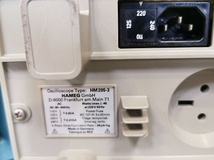
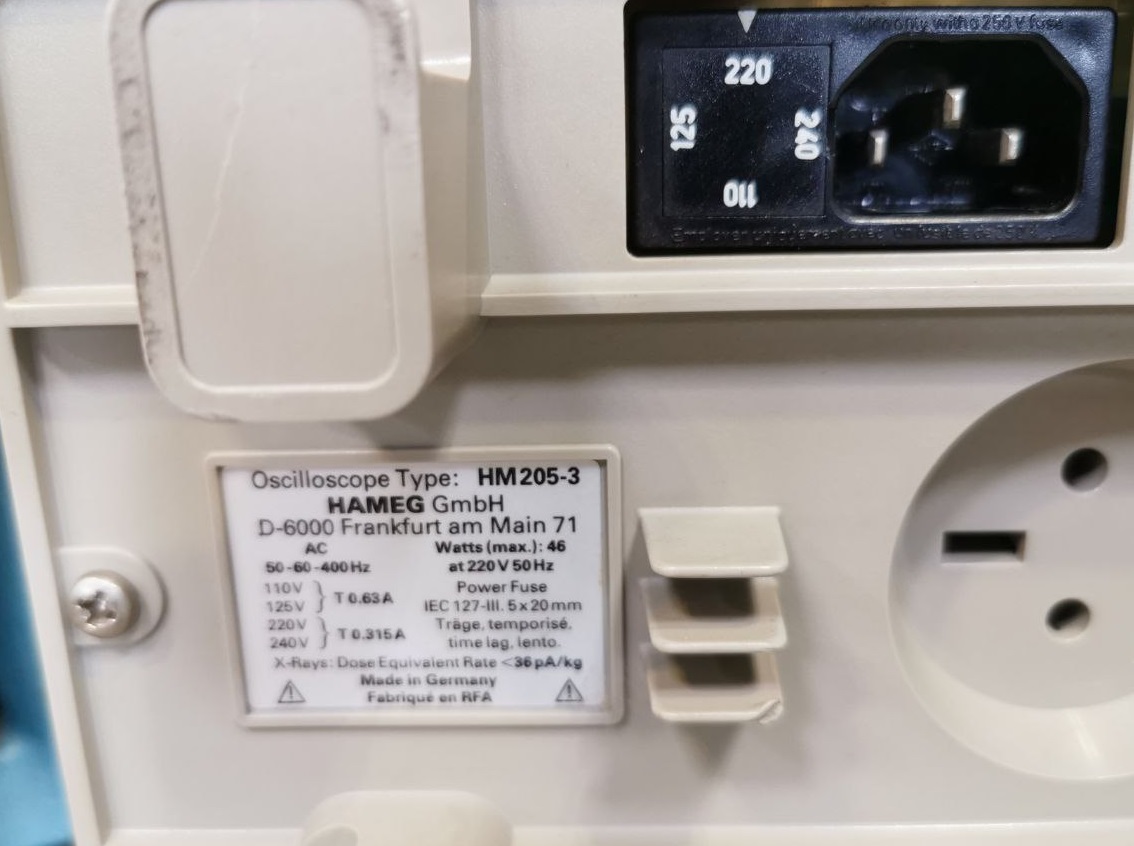
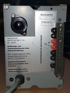
Oscilloscope Type: HM205-3
HAMEG GmbH
D-6000 Frankfurt am Main 71
Watts (max.): 46
at 220 V 50 Hz
AC 50-60-400 Hz
110V T 0.63A
125V
220V T 0.315A
240V
IEC 127-III. 5x20mm
träge, temporisé,
time lag, lento
X-Rays: Dose Equivalent Rate < 36 pA/kg
Made in Germany
Fabrique en RFA
packageName~(~%27TO220))&visibleColumnIds=name,productStatusInfo,orderOnline,opn,522,packageName,869_max,559_93_max,559_90_max,547_136_nom,547_135_nom,478_min,478_max,478_nom,451_154_max,830,529,618,551,284_min,284_max,681_nom Selbst wenn man sich kein SOT23 zutrauen sollte, es gibt auch in SMD recht
IRLB8721PBF Infineon Technologies FDP8896 onsemi NTP4813NLG onsemi PSMN022-30PL,127 Nexperia USA Inc. PSMN2R0-30PL,127 Nexperia USA Inc. Farnell hat nur einen Vorschlag INFINEON-IRLB8721PBF Richie hat mal mehrere aufgesägt, 4 Originale, 3 Fälschungen: https://www.richis-lab.de
TOM. There are two cases that give a transition without Compare Match. OCR0A changes its value from MAX, like in Figure 14-7. When the OCR0A value is MAX the OCn pin value is the same as the result of a down-counting Compare Match. To ensure symmetry around BOTTOM the OCn value at MAX must correspond
frequency divided by R Heisst das in meinem Fall, dass bei 10MHz Referenzsignal und einem R von max. 65535 sich ein ~152Hz Raster ergibt auf welches abgestimmt werden kann (natürlich vom geteilten Signal).
10MHz und R = 400 läge die kleinste Schrittweite dann bei fr = 10MHz / R = 25kHz. Da der TBB200 nur max. 30Mhz (Dual-Modulus) verarbeiten kann, muss ein geeigneter Vorteiler (Prescaler) P|(P+1) (z.B. 32/33) die VCO-Frequenz herunterteilen. Bei der max. VCO-Frequenz von 570MHz läge die max.Eingangsfrequenz
The maximum allowable continuous power dissipation at any ambient temperature is calculaDed by PTJ(MAX)- Lead Temperature ....................................260C TA/ JA. Exceeding the maximum allowable power dissipation Storage Temperature.............. –65°C to +150C will cause excessive die temperature
=100 kBit/s 4=125 kBit/s 5=250 kBit/s 6=500 kBit/s 7=800 kBit/s 8=1000 kBit/s 2101 Node number 1...127 possible After 0 Node Number U8 RW 01h Yes setting the baud rate, the EEPROM must be saved and reinitialized. Object 2002h: Speed Only for standard encoder with software version >=1.01 : DeviceName
11. Technische Daten Type Motor n-Stufen Bohrleistung Gesamthöhe Spindel Gewicht Drehzahlen min-1 max.Bohrtiefe max. Ausladung TB-16/12 230 V oder 400 V 12 20 mm 837 mm MK2 38 kg 750 W 180 - 3800 60 mm 127 mm TB-20/12E 230 V oder 400 V 12 20 mm 955 mm MK2 60 kg 750 W 210 - 2580 83 mm 170 mm TB-20/12
Das Gerät hat gebootet. 4 STOPPED Das Gerät ist gestoppt. 5 OPERATIONAL Das Gerät arbeitet normal. 127 PRE-OPERATIONAL Das Gerät sendet keine PDOs, kann aber SDOs bearbeiten. Stand 30.01.2014 HYDAC ELECTRONIC GMBH Mat.-Nr.: 669821 Protokoll-Beschreibung CANopen HDA 4000/7000 Seite 13 Der HDA 4000/7000
cycle. The valid range is from 0 to 128. 0 means backlight completely off, 128 means backlight in max brightness. Register Definition 83 – REG_PWM_DUTY Definition REG_PWM_HZ Definition 31 14 13 0 Reserved r/w Offset: 0xD0 Reset Value: 0xFA Bit 31 – 14: Reserved Bits Bit 13 – 0: These bits define the

 Bild
Bild
 Bild
Bild
 Bild
Bild