-
Datei
Voltmeter_tiny24_dick_und_fett_Anode2.bas
'**************************VOLTMETER-TEST von PAUL BAUMANN $regfile = "atTiny24.dat" 'ATTiny24-Deklarationen $crystal = 1000000 'Interner Takt benutzt ' variablen für die display routine Dim Tempstr As String * 3 Dim Y As Byte Dim Tempbyte As Byte ' Variable für Digitansteuerung
in „7segment in bascom“ · Mikrocontroller und Digitale Elektronik ·
-
Datei
lcd_clock_Tiny2313.bas
'from www.pro-qwerty.com $regfile = "attiny2313.dat" $crystal = 8000000 Pind = &B01000000 'Portd alle Eingang außer Pd6 (ICP) Portd = &B0011100 'Pull Ups an Taster 1 2 3 Dim A As Byte , Sekunde As Byte , Minute As Byte , Stunde As Byte Let Sekunde
in „Uhr mit LCD Display funktioniert nicht“ · Mikrocontroller und Digitale Elektronik ·
-
Datei
RFID-Reader-Modul.c
/* / Projektname : RFID-Reader-Modul / Dateiname : RFID-Reader-Modul.c / Version : 1.0.0 - ATtiny2313 / Datum : 28.12.2013 / Compiler : WinAVR 20100110 libc 1_7_1 / Autor : Johannes Kretzmann / Copyright : johannes.kretzmann@projektsammlung.de / www.projektsammlung.de / / / / Mikrocontroller: ATtiny2313
in „Attiny2313 eeprom Fragen“ · Mikrocontroller und Digitale Elektronik ·
-
Datei
VM_tn24_1.bas
'**************************VOLTMETER-TEST $regfile = "atTiny24.dat" 'ATTiny24-Deklarationen $crystal = 1000000 'Interner Takt benutzt Dim Bimu(12) As Byte 'Bitmuster für Zeichen Dim Dimu(3) As Byte 'Digit-Bitmuster Dim Zeichen(3)as Byte 'Bitmuster zur Ausgabe Dim
in „Bascom: Variable aufteilen für 7-Segment Anzeigen“ · Mikrocontroller und Digitale Elektronik ·
-
Datei
VM_tn24_1.bas
'**************************VOLTMETER-TEST von PAUL BAUMANN und Hannes Lux $regfile = "atTiny24.dat" 'ATTiny24-Deklarationen $crystal = 1000000 'Interner Takt benutzt Dim Bimu(12) As Byte 'Bitmuster für Zeichen Dim Dimu(3) As Byte 'Digit-Bitmuster Dim Zeichen(3)as Byte 'Bitmuster zur Ausgabe Dim
in „attiny24 und 7 Segmentanzeige“ · Mikrocontroller und Digitale Elektronik ·
-
Datei
programm.asm
.nolist .include "tn13adef.inc" ; Define device ATtiny13A .list .def sreg_bak = R15 .def rmp = R16 .def zero = R17 .def eepromadresse = R18 .def eeprominhalt = R19 .def rmp2 = R20 .def counterlow = R24 .def counterhigh = R25 .def sollwertlow = R26 .def sollwerthigh = R27 .equ maximalwert = 1000 ; 10800 = acht sekunden mal 10.800 => 24h .equ LED = 4 ;PORTB1 .equ WERTE = 12 ; Anzahl der .db-Werte .eseg .org 0 .db LOW(100), HIGH(100) ; an .db LOW(120), HIGH(120) ; aus .db LOW(300), HIGH(300) ; an .db LOW(350), HIGH(350) ; aus .db LOW
in „Programm läuft - aber nur direkt nach flashen“ · Mikrocontroller und Digitale Elektronik ·
-
Datei
mpx_2digit_ntc.c
gemeinsame Anode) und NTC-Widerstand 10k, Beta 3950 NTC-Widerstand an PA0 mit Pop-Upwiderstand 10k MCU : attiny84 F_CPU : 8000000 07.02.2022 by R. Seelig ------------------------------------------------------------ */ #include <util/delay.h> #include <avr/io.h> #include <avr/pgmspace.h> #include <avr/interrupt.h> #include "adc_single.h" #include "mpx_2conc.h" /* ATtiny 24 / 44 / 84 Anschlusspins IC +-----------+ Vcc | 1 A 14 | GND PB0 - PCINT8 - XTAL1 - SCI - CLKI | 2 T 13 | PA0 - ADC0 - AREF - PCINT0 PB1 - PCINT9 - XTAL2 | 3 t 12 | PA1 - ADC1 - AIN0 - PCINT1 PB3
in „7 Segment Anzeige auf verschiedenen Ports“ · Mikrocontroller und Digitale Elektronik ·
-
PDF
assembler_beginner.pdf
................................................................3 2.3 Experimentierschaltung mit ATtiny13....................................................................................................4 2.4 Experimentalschaltung mit AT90S2313/ATtiny2313............................................
in „Assembler Tutorial als PDF ?“ · Mikrocontroller und Digitale Elektronik ·
-
PDF
catalog.pdf
Analogue Converter, 20 bit, 1 MSPS, Serial, 2.7V to 5.5V, TSSOP, 20 RoHS Compliant: Yes EEPROM MPN: M24M01-RMN6TP [ID]: 000029 [Price]: 1.09 USD [QTY]: 3 [Category]: EEPROM [Desc]: M24M01 Series 1 Mb (128 K x 8) 1.8 V SMT Serial I²C Bus EEPROM - SOIC-8 MPN: M24M02-DRMN6TP [ID]: 000031 [Price]: 2.43 USD [QTY]: 5 [Category]: EEPROM [Desc]: M24M02-DR Series 2 Mb (256 K x 8) 5.5 V Serial I²C bus EEPROM - SOIC-8 MPN: M24C04-WDW6TP [ID]: 000309 [Price]: 0.17 USD [QTY]: 5 [Category]: EEPROM [Desc]: M24C04 Series 4 Kb (512 x 8) 2.5 V SMT Serial
-
PDF
catalog.pdf
2.7V to 5.5V, TSSOP, 20 RoHS Compliant: Yes Page 34/105 Bauteileliste vom 12.08.2022 EEPROM MPN: M24M01-RMN6TP [ID]: 000029 [Price]: 1.09 USD [QTY]: 3 [Category]: EEPROM [Desc]: M24M01 Series 1 Mb (128 K x 8) 1.8 V SMT Serial I²C Bus EEPROM - SOIC-8 MPN: M24M02-DRMN6TP [ID]: 000031 [Price]: 2.43 USD [QTY]: 5 [Category]: EEPROM [Desc]: M24M02-DR Series 2 Mb (256 K x 8) 5.5 V Serial I²C bus EEPROM - SOIC-8 MPN: M24C04-WDW6TP [ID]: 000309 [Price]: 0.17 USD [QTY]: 5 [Category]: EEPROM [Desc]: M24C04 Series 4 Kb (512 x 8) 2.5 V SMT Serial
-
Datei
tn2313def__2_.inc
Y ;* ;* Number :AVR000 ;* File Name :"tn2313def.inc" ;* Title :Register/Bit Definitions for the ATtiny2313 ;* Date :03.06.17 ;* Version :1.00 ;* Support E-mail :avr@atmel.com ;* Target MCU :ATtiny2313 ;* ;* DESCRIPTION ;* When including this file in the assembly program file, all I/O register ;* names
in „Welche .def ist die richtige?“ · Mikrocontroller und Digitale Elektronik ·
-
Datei
iotnx61.h
/* $Id: iotnx61.h,v 1.6 2007/12/12 14:00:49 arcanum Exp $ */ /* avr/iotnx61.h - definitions for ATtiny261, ATtiny461 and ATtiny861 */ /* This file should only be included from <avr/io.h>, never directly. */ #ifndef _AVR_IO_H_ # error "Include <avr/io.h> instead of this file." #endif #ifndef _AVR_IOXXX_H
in „Fehler in ATtiny461 Definitions-Header“ · Mikrocontroller und Digitale Elektronik ·
-
PDF
catalog-3.pdf
2.7V to 5.5V, TSSOP, 20 RoHS Compliant: Yes Page 34/105 Bauteileliste vom 12.08.2022 EEPROM MPN: M24M01-RMN6TP [ID]: 000029 [Price]: 1.502 USD [QTY]: 3 [Category]: EEPROM [Desc]: M24M01 Series 1 Mb (128 K x 8) 1.8 V SMT Serial I²C Bus EEPROM - SOIC-8 MPN: M24M02-DRMN6TP [ID]: 000031 [Price]: 3.3485 USD [QTY]: 5 [Category]: EEPROM [Desc]: M24M02-DR Series 2 Mb (256 K x 8) 5.5 V Serial I²C bus EEPROM - SOIC-8 MPN: M24C04-WDW6TP [ID]: 000309 [Price]: 0.2343 USD [QTY]: 5 [Category]: EEPROM [Desc]: M24C04 Series 4 Kb (512 x 8) 2.5 V SMT Serial
-
Datei
Bootloader.bas
********** '****** Bootloader Einstellungen ************************ 'AVR Controller $regfile = "attiny45.dat" $crystal = 8000000 'Page Grösse im Flash Const Page_size = 32 'Anzahl Word pro Page ist im Datenblatt des jeweiligen AVR ersichtlich. 'Bootloader bei Adresse: Const Bootloader_adress_absolut
in „Probleme beim Flashen mit Bascom“ · Mikrocontroller und Digitale Elektronik ·
-
Datei
main.c
// // * * Arras_24.c // * Ausgeführt an Attiny-LED-root-4.fzz Fritzing 2.2.2019 // * // * Created: 18.1.2019 19:51:26 // * Author : fjm // * // ********************************************** // * Hell- und Farbsteuerung
in „Zwei PWM steuern LED-Steifen mit Attiny 85,Schaltbild neu“ · Mikrocontroller und Digitale Elektronik ·
-
Datei
Laufschr.asm
*************************** ; Test fuer LCD Laufschrift ; - - - - - - - - - - - - - - - - ; MCU: Attiny4313 (resp. 2313) ; MCU clock: STK500-Board (unkritisch bis ca.4MHz) ; LCD 2x16; Vierbitmodus ; - - - - - - - - - - - - - - - - ; PortD LCD Ausgabe: R/Wquer=GND ; PD7 PD6 PD5 PD4 PD3 PD2 PD1 PD0 ; n
in „LCD Lauftext Atmega8“ · Mikrocontroller und Digitale Elektronik ·
-
Datei
qenc.asm
und Down-Signal und Richtungsbit aus x4-Dekodierung, d.h. es wird JEDE Flanke ausgewertet. CPU: ATTiny13 /----------+ / | --|1 Rst Vcc 8|-- +5V | | Sig A >--|2 PB3 PB2 7|--> Dir | | Sig B >--|3 PB4 PB1 6|--> Down | | 0V --|4 GND PB0 5|--> Up | | +-----------+ Fuses: 7A, (Divide by 8 abgeschaltet) Author: Ralf Dreiling Datum : 24.04.2010 vorwärts rückwärts ____ ____ ____ ____ ____ ____ ____ | | | | | | | | | | | | SigA ___| |___| |___| |___ |___| |___| |___| ____ ____ ____ ____ ____ ____ ____ | | | | | | | | | | | | | SigB __
-
PDF
isel-interface.pdf
c18 IDIR_Z 16 Watchdog / PWM R4 6 2 17 Stromabsenkung 11 REF_Y 11 C2 3 k ICLK_Z a19 c19 18-25 GND 24 13 4 R 4 A2 IREF_Z ISTBY a20 c20 ISTBY 330R D 12 REF_Z G 5 REF_Z VO2 3 ISTBY a21 c21 6 R16 25 C2 330R a22 c22 13 IN1 4 a23 c23 U3A VCC N 5 74LS132 U7 C G a24 c24 J1 DIR_X 1 V 8 2 7 a25 c25 R5 R 4 3 A1
in „kleiner Wachhund für CNC-Steuerungen“ · Projekte & Code ·
-
Datei
Thermometer.asm
;IDE : AVRStudio V4.09 ;µC : ATtiny15L ;Thermometer mit LED-Segmentanzeige .include "tn15def.inc" ; .def Ziffer = r20 ;Dualzahl-Buffer .def ZBuffer = r16 ;Zeichen-Buffer .def LEDAdresse = r17 ;Multiplexer-Adresse .def temp = r18 ;Temporär-Register
in „kleines Problemchen bei ADC-Messung...“ · Mikrocontroller und Digitale Elektronik ·
-
Datei
sweep_test.asm
************************************************************* ;*Programm Sweep_test.ASM ;* ;*Für ATtiny13 mit internen voreingestellten Takt von ??? Hz ;* ;* ;* Zwei synchrone symetrische Rechtecksignale können über ein Poti in ihrer Frequenz ;* im Bereich von 62,5Hz bis 16kHz verändert werden. ;* ;*
in „ATtiny13 LED-blinken an PB2 und PWM-Mode 7 nicht möglich“ · Mikrocontroller und Digitale Elektronik ·
-
Datei
Display_DMC20247.c
Wertewahl über Tasten // Compiler : WinAVR v20100110 (http://sourceforge.net/projects/winavr/) // MCU : ATtiny2313 (bzw. ATtiny4313) // Quarz : 16,00 MHz // Versionen : 21.07.2011 - V1.0 // - Erste öffentliche Version // // Copyright : (C) 2011 Mathias Arp (mathias@mathias-arp.de) //========================
in „Ansteuerung Display DMC2047 mit ATtiny 2313“ · Mikrocontroller und Digitale Elektronik ·
-
Datei
Display_DMC20247.c
Wertewahl über Tasten // Compiler : WinAVR v20100110 (http://sourceforge.net/projects/winavr/) // MCU : ATtiny2313 (bzw. ATtiny4313) // Quarz : 16,00 MHz // Versionen : 21.07.2011 - V1.0 // - Erste öffentliche Version // // Copyright : (C) 2011 Mathias Arp (mathias@mathias-arp.de) //========================
in „Pollin Display DMC 2047“ · Mikrocontroller und Digitale Elektronik ·
-
PDF
Halbleiterliste.pdf
datasheet-pdf/view/521358/ROCHESTER/D8251A.html Intel D8253 1 Programmable Timer, 3 Timer(s), NMOS, CDIP24 NEC D8253-5 10 Programmable Timer, 3 Timer(s), NMOS, PDIP24 Intel D8254-2 1 Programmable Interval Timer Intel D8255A 2 Parallel I/O Port, 24 I/O, CMOS Intel D8259A 2 Interrupt Controller, 8080A; 8085A
-
PDF
GCC_Tut_Test.pdf
< CNTREPEAT) gKeyCounter++; 87a: 80 91 2a 03 lds r24, 0x032A 87e: 88 3c cpi r24, 0xC8 ; 200 880: 40 f4 brcc .+16 ; 0x892 <__vector_13+0x28> 882: 80 91 2a 03 lds r24, 0x032A 886: 8f 5f subi r24, 0xFF ; 255 888: 80 93 2a 03 sts 0x032A, r24 88c: 02 c0 rjmp
-
Datei
TurntableStrobe.c
<avr/io.h> #include <avr/interrupt.h> #include <util/delay.h> /** * Turntable Strobe driver for ATtiny25 family * * @description: Firmware for TurntableStrobe used to calibrate * turntable speed. Most turntables use some form of incandescent bulb * running off mains, which means they light up twice
in „Compile Error AVR MAc“ · Mikrocontroller und Digitale Elektronik ·
-
Datei
tn13servo1.asm
/* Servoimpulsgenerator mit zwei Tastern und zwei Servopositionen mit ATTiny13 Beispielprogramm für Rolf Hegewald zum leichteren Einstieg in die AVR-ASM-Welt 01/2012 www.hanneslux.de Mit den Tastern kann (gemäß einem RS-Flipflop) zwischen zwei Zuständen umgeschaltet werden.
in „Taster-Entprellung am Tiny13 in Assembler“ · Mikrocontroller und Digitale Elektronik ·
-
Datei
owdevice_ATT13_DS18B20.c
/* * owdevice.c * * Created: 24.01.2012 14:11:43 * Author: Tobias Mueller, mail(at)tobynet.de * Bitte bei weiterer Verabeitung immer angeben */ #include <avr/io.h> #include <avr/interrupt.h> #ifdef __AVR_ATmega32__ #include "uart.h" #include <util/delay.h> #endif //DEVICES #ifdef __AVR_ATtiny13A__ // OW_PORT Pin 6 - PB1 #define OW_PORT PORTB #define OW_PIN PINB #define OW_PORTN (1<<PINB1) #define OW_PINN (1<<PINB1) #define OW_DDR DDRB #define SET_LOW OW_DDR|=OW_PINN;OW_PORT&=~OW_PORTN;
in „1-Wire Slave auf AVR“ · Mikrocontroller und Digitale Elektronik ·
-
Datei
owdevice_ATT13_DS2423.c
/* * owdevice.c * * Created: 24.01.2012 14:11:43 * Author: Tobias Mueller, mail(at)tobynet.de * Bitte bei weiterer Verabeitung immer angeben */ #include <avr/io.h> #include <avr/interrupt.h> #ifdef __AVR_ATmega32__ #include "uart.h" #include <util/delay.h> #endif //DEVICES #ifdef __AVR_ATtiny13A__ // OW_PORT Pin 6 - PB1 #define OW_PORT PORTB #define OW_PIN PINB #define OW_PORTN (1<<PINB1) #define OW_PINN (1<<PINB1) #define OW_DDR DDRB #define SET_LOW OW_DDR|=OW_PINN;OW_PORT&=~OW_PORTN;
in „1-Wire Slave auf AVR“ · Mikrocontroller und Digitale Elektronik ·
-
Datei
servobremse01.asm
/* Servo-Bremse mit ATTiny13 Dient zum Verlangsamen von Servobewegungen und zum Justieren von Neutralpunkt und Drehwinkel. Anschlussbewegung ATTiny13: Pin 1: PB5, Reset Pin 2: PB3, ADC 3 Neutralpunkt Pin 3: PB4, ADC 2 Gain Pin
in „Ich verstehe den Timer0 beim ATtiny 13 nicht.“ · Mikrocontroller und Digitale Elektronik ·
-
Datei
adc-test.asm
;---------------------------------------------------------------------- ; ADC-Testprogramm mit ATtiny13 ; Erläuterungen: www.schramm-software.de/tipps ;---------------------------------------------------------------------- ; Prozessor : ATTiny13 ; Takt : 4,8 MHz ; Sprache : Assembler ; Version : 1.0
in „ADC-Input und Auswahlverfahren“ · Mikrocontroller und Digitale Elektronik ·
-
Datei
quelltext.c
delay.h> #include <avr/interrupt.h> #include <avr/io.h> #include "hardware.h" // Im Makefile: // MCU = attiny13 // F_CPU = 1200000 // Enable the two PWM outputs #define ENABLE_PWM_OUTPUTS { DDRB |= (1<<PB0) + (1<<PB1); } // The Status LED output #define STATUS_LED_ON { DDRB |= (1<<PB2); PORTB |= (1<<PB2);
in „Netzteil für 3 mA“ · Mikrocontroller und Digitale Elektronik ·
-
PDF
SRAM.pdf
Die Speicherbelegung des ATTiny 4313 .ESEG ; EEPROM-Bereich daten_eeprom: favorit1: .byte 6 ;Tastenkombination fürTaste 1+2 favorit2: .byte 6 ;Tastenkombination fürTaste 1+3 favorit3: .byte 6 ;Tastenkombination fürTaste 1+4 favorit4
in „4-fach Dimmer 2Stromstoßschalter Schaltuhr“ · Projekte & Code ·
-
PDF
VQC10_LED_Matrix.pdf
*/ -3- 5 + IC4 GND 2 CP1 VCC 14 IC1 IC2 IC3 5 16 2 14 2 14 2 14 CP2 VSS CP1 VCC CP1 VCC CP1 VCC 9 24 CP3 VSS 5 CP2 VSS 16 5 CP2 VSS 16 5 CP2 VSS 16 12 CP4 9 CP3 VSS 24 9 CP3 VSS 24 9 CP3 VSS 24 Z1 20 12 12 12 CP4 CP4 CP4 21 20 20 20 Z2 Z1 Z1 Z1 1 19 D1 Z3 Z2 21 Z2 21 Z2 21 8 D2 Z4 22 1 D1 Z3 19 1 D1
in „Mega8: VQC10 LED-Matrix 5x7 Zeitmultiplex - Bestimmte Bits eines unsigned char auf Ports ausgeben“ · Mikrocontroller und Digitale Elektronik ·
-
Datei
Heizungsschieber.asm
**************************************** ; ; Include-Datei fuer den betreffenden AVR-Typ .DEVICE ATtiny45 .NOLIST .INCLUDE "tn45def.inc" ; Headerdatei fuer ATTINY45 .LIST .LISTMAC ; ; ============================================ ; H A R D W A R E I N F O R M A T I O N E N ; ==========================
in „ATtiny45 - Timer 'Problem' - Assembler“ · Mikrocontroller und Digitale Elektronik ·
-
Datei
DUO_LED_12.asm
*********************************************************************** ;* DUO_LED.ASM ;* ;* Für ATtiny26 mit internen Kalibrierten RC-Oszilator von 1Mhz ;* ;* Eine 3-Pinn DUO_LED soll durch die Farben Rot, Gelb und Grün verschiedene ;* ;* Zustände Signalisieren. Diese Grundfarben sollen nochmals durch
-
PDF
AVR310_Using_the_USI_module_as_a_I2C_master.pdf
multiple masters on the bus. The Universal Serial Interface (USI) module on devices like ATmega169, ATtiny26 and ATtiny2313 has a dedicated Two-wire mode. The USI provides the basic hardware resources needed for synchronous serial communication. Combined with a minimum of control software, the USI allows
in „ATTiny2313 I2C - Master (Peter Fleury) / Slave (jtronics)“ · Mikrocontroller und Digitale Elektronik ·
-
Datei
RGB.asm
TIMSK,r20 ; Timer0 und Timer1 Interrupt freigeben BITFERTIG1: ldi r20,0b00000001 ; Flanke tokeln eor r24,r20 out MCUCR,r24 out SREG,r15 ldi r20,0b01000000 ; Sicherheitshalber Interruptflag löschen (Einschwinger) out GIFR,r20 out SREG,r15 reti NOFSTARTBIT: cpi r26,255 brne DATABIT cpi r25,55 ; Wenn das Startbit
in „PWM und rgb led“ · Mikrocontroller und Digitale Elektronik ·
-
PDF
AVR_ISP_USER_GUIDE.PDF
that the firmware in the pro- grammer is outdated. The following devices are currently supported: ATtiny12 ATtiny15 ATtiny22 AT90S1200 AT90S2313 AT90S/LS2323 AT90S/LS2343 AT90S/LS2333 AT90S4414 AT90S/LS4433 AT90S/LS4434 AT90S8515 AT90S/LS8535 ATmega161(L) ATmega16(L) ATmega163(L) ATmega32(L) ATmega323
-
Datei
dann.lst
1 .file "dann.c" 2 .arch attiny26 3 __SREG__ = 0x3f 4 __SP_H__ = 0x3e 5 __SP_L__ = 0x3d 6 __tmp_reg__ = 0 7 __zero_reg__ = 1 8 .global __do_copy_data 9 .global __do_clear_bss 11 .text 12 .Ltext0: 49 .global display_write 51 display_write
in „Welchen WINAVR nehmen ?“ · Mikrocontroller und Digitale Elektronik ·
-
Datei
dw_fuse_loeschen.txt
>avrdude -p attiny48 -P usb -c dragon_isp -U hfuse:w:0xDF:m -vvvv avrdude: Version 6.1, compiled on Mar 13 2014 at 00:09:49 Copyright (c) 2000-2005 Brian Dean, http://www.bdmicro.com/ Copyright (c) 2007-2014 Joerg Wunsch
in „avrdude fuses aus debugwire schreiben“ · Mikrocontroller und Digitale Elektronik ·
-
Datei
AVR8_Burn_O_Mat_Config.xml
0"/> </BrownOutDetection> <OscillatorOptions Type="ATmega8" /> </AVR> <AVR name="t2313" caption="ATtiny2313"> <Fuse name="UNUSED_E7" bit="7" fuseByte="efuse" default="1" desc="unused" mode="expert"/> <Fuse name="UNUSED_E6" bit="6" fuseByte="efuse" default="1" desc="unused" mode="expert"/> <Fuse name=
-
PDF
Bauteile.pdf
ADS114S08BIPBSR PQFP32 Texas Instruments 3,00 60 ADS1248IPW TSSOP28 Texas Instruments 3,00 40 AD7730BRU TSSOP24 Analog Devices 10,00 30 AD7738BRU TSSOP28 Analog Devices 10,00 45 ADS1118IDGSR MSOP10 Texas Instruments 1,50 20 ATTINY402-SSFR SO8 Microchip 0,25 40
in „[V] Verschiedene Bauteile“ · Markt ·
-
 Bild
Bild
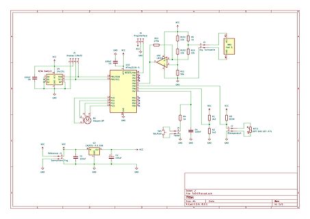
Schaltplan einer Mikrocontroller-Schaltung
J6 Progrinterface, R12 270k, R105, R5, J3, Hall S., VCC, GND, U5 ATtiny85-S, U4 24LC01, C5 100nF, C6 100nF, PB1/SDA, PB0/SCL, PC0 bis PC7, PB2 bis PB7, M1 Stepper_BP, U2 LM2931-5.0, Sannuvers Fzg., C1 100nF, C2 100uF, SW1 Sw_Push, Tester, C4 100nF, R4 1k, R1 2k2, R3 820R
in „Digitaltacho - Spannungswandler Motorrad 6V & 12V zu 5V“ · Mikrocontroller und Digitale Elektronik · · Schaltpläne
-
 Bild
Bild
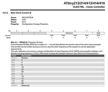
Datenblatt Ausschnitt ATtiny212/214/412/414/416 Clock Controller
ATtiny212/214/412/414/416 CLKCTRL - Clock Controller 10.5.2 Main Clock Control B Name: MCLKCTRLB Offset: 0x01 Reset: 0x11 Property: Configuration Change Protection Bit 7 6 5 4 3 2 1 0 Access R/W R/W R/W
in „ATTiny 412 OOK Modulation“ · Mikrocontroller und Digitale Elektronik · · Screenshots
-
Datei
foo.c
// avr-gcc -mmcu=attiny24 foo.c -Os -S -ffixed-2 -ffixed-3 register volatile unsigned int currData asm ("r2"); typedef unsigned int uint8_t __attribute__((__mode__(__QI__))); #define PINB (*(volatile uint8_t *)(0x16 + 0x20
in „Variable an Register binden - ich kanns nicht oder compilerbug :)“ · Mikrocontroller und Digitale Elektronik ·
-
Datei
VU-Meter.c
/* * VU Meter für ATTiny 25 (45/85) für 10 oder 12 LEDs (z.B. 9 grün, 2 gelb, 1 rot) * 15.3.17 * Anregung von https://www.mikrocontroller.net/topic/419372 - dort ist die HW mit einem Tiny13 beschrieben * * Taktfrequenz 8MHz
in „ATTiny25: unklare Interaktion PROGMEM <-> ADC“ · Mikrocontroller und Digitale Elektronik ·
-
Datei
irmpconfig.h
150 bytes #define IRMP_SUPPORT_S100_PROTOCOL 0 // S100 >= 10000 ~250 bytes #define IRMP_SUPPORT_ACP24_PROTOCOL 0 // ACP24 >= 10000 ~250 bytes #define IRMP_SUPPORT_RADIO1_PROTOCOL 0 // RADIO, e.g. TEVION >= 10000 ~250 bytes (experimental) /*-------------------------------------------------------------
in „Umfrage: welche IR-Protokolle nutzt ihr mit IRMP?“ · PC Hard- und Software ·
-
Datei
ampelpluslauflicht.asm
Musters 1 - max in der Teiltabelle .def Taster = R23 ; aktuelle Nummer der LEDTeiltabelle .def max = R24 ; aktuelle Länge der Teiltabelle ; Programm Anfang ===================================================== .org 0x0000 ; Start ist hier rjmp Init ; Sprung zum Hauptprogramm ; .org OC1Aaddr ; Timer soll
in „AVR LED Lauflicht flexibel mit Pollin Platine (+Ampel ;-)“ · Projekte & Code ·
-
Datei
t13schalt4_1.asm
/* RC-Schaltmodul mit 4 Schaltausgängen mit ATTiny13 Es wird der Kanalimpuls einer Modellbau-Funkfernsteuerung ausgewertet. Es können 4 Schaltausgänge geschaltet werden. Für jeden Schaltausgang kann durch bedingte Assemblierung die Betriebsart separat
in „Ich verstehe den Timer0 beim ATtiny 13 nicht.“ · Mikrocontroller und Digitale Elektronik ·
-
Datei
Fotograf_zufall_v1-attiny13.bas
Fotograf_zufall_v1, LED per Zufall einfach,doppelt oder garnicht Blitzenlassen $crystal = 8000000 $regfile = "attiny13.dat" $hwstack = 32 $swstack = 8 $framesize = 24 Config Portb.1 = Output Config Debounce = 30 '------------------------------------------------------------------- 'Dim Z As Word ' Dim Z As Eram Word
in „Compilierungsfehler 242 beim ATTiny13“ · Mikrocontroller und Digitale Elektronik ·