Nachbauvariante hinweisen: [c] 1. This is NOT a copy of the original function generator, but it uses the same interface and same DAC. 2. This design is optimized for cheap production including assembly, by the minimizing the amount of "extended components" from the JLCPCB manufacturer. 3. Minimizing
Produkts vermeldet man dann folgendes: [c] Raspberry Pi Camera Module 3 Sensor Assemblies offer the same IMX708 4608×2592 (11.9 megapixel) sensor, with 1.40μm pixels, and the same Phase Detection Autofocus (PDAF) capability as Camera Module 3. We are providing reference schematics and a bill of materials
180 V , DC BLOCKING VOLTAGE (V) T , LEAD TEMPERATURE (°C) R L Figure 3. Typical Capacitance Figure 4. Maximum Current Ratings http://onsemi.com 2 MR2535L 1 45 ) 40 L E C ) Maximum M I N /35 R A T ° Typical E M I (30 T R E A Single to heatsink T N R L25 E (0.1 L Maximum S C M T20 N N R N R T H I15 Typical
außen so zusammengelegt wurden, dass das nicht mehr geht. Beim Trotec Lokales Klimagerät PAC 2015 E geht es zum Beispiel noch. Bei vielen Zweischlauchgeräten steht nicht verfügbar: https://www.amazon.de/Sichler-Exclusive-Klimager%C3%A4t-mobil-Monoblock-Klimaanlage/dp/B088TQ331G
ganze Wohnung problemlos um 15° C Grad > runter. Das Ding gab es vor zwei Jahren für € 199,- auf eBay.
CURRENT (mAdc) Figure 1. Normalized DC Current Gain Figure 2. “Saturation” and “On” Voltages 2.0 1.0 V C E TA= 25°C / -55°C to +125°C G m 1.2 L 1.6 T O N V C = 200 mA C 1.6 E F I 1.2 E M C = IC= C = 50 mA C = 100 mA C 2.0 - 10 mA 20 mA E O 0.8 U C A 2.4 E R O P , 0.4 E 2.8 E , VC V θ 00.02 0.1 1.0 10 20 0.2
EVs. battery packs that exceed 400 VDC, often in the 600 to 800 VDC range. 920 V DC Typical Typical eTruck ABB Terra Premium eBus chargers eCar 600-850 up to 800 550-800 VDC VDC HV VDC 500 V charging DC DCFC Typical Typical 150-920 eCar 500 VDC VDC 200-450 DCFC VDC 150 V DC Infrastructure Vehicle — A
for Rs for L_out L_out = E3´L +E4´C+E7´Ls+E8´Rs R_out = E3´R +E4´C+E5´Ls+E6´Rs L, R, C, Ls, Rs are input cross bar mixer outputs. L, R, C, Ls, Rs are defined as the output of input mixers. L = Ch1, R = Ch2, C = Ch8, Ls = Ch3,
Seeed Studio erweitert man die XIAO-Plattform um eine Variante, die neben einem Funkinterface auch PoE und Ethernet unterstützt. Spezifischerweise kombiniert die neueste Variante des Xiao-Ökosystems einen WizNet W5500 und einen ESP32-S3. 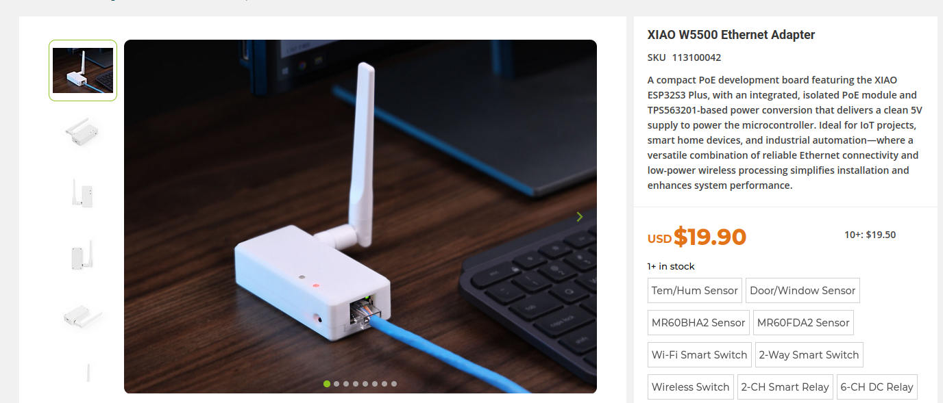 Bildquelle. https://www.seeedstudio.com
Danke für den Hinweis auf das e-Fleisch. Eine interessante Idee.
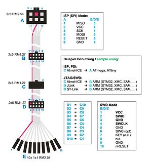
pinout are supported, depending on the cabling and adapters included with the particular kit. Figure 4-2. SAM JTAG Header Pinout 1 2 VCC TMS GND TCK GND TDO (KEY) TDI GND nRESET SAM JTAG Table 4-1. SAM JTAG Pin Description Name Pin Description TCK 4 Test Clock (clock signal from the Atmel-ICE into the
SOT-666 package information 3.2 SOT-666 package information Figure 20. SOT-666 package outline b L1 E1 D A A3 L2 E e Table 4. SOT-666 package mechanical data Dimensions Ref. Millimeters Inches (1) Min. Typ. Max. Min. Typ. Max. A 0.45 0.62 0.018 0.025 A3 0.08 0.18 0.003 0.007 b 0.17 0.34 0.007 0.013 D 1.50 1.70 0.059 0.067 E 1.50 1.70 0.059 0.067 E1 1.10 1.30 0.043 0.051 e 0.50 0.020 L1 0.19 0.007 L2 0.10 0.30 0.004 0.012 1. Value in inches are converted from mm and rounded to 4 decimal digits DS4260 - Rev 7 page 14/20 USBLC6
...........................................................11 4.2. Port E Data Direction Register................................................................................................... 12 4.3. Port E Data Register......................................
Enable STB Data Latch CE# Output Enable OE# Logic Y-Decoder Y-Gating STB V Detector Timer t CC a L e X-Decoder Cell Matrix d A0–A18 d A 4 Am29F040B 21445E8 November 11, 2009 D A T A S H E E T CONNECTION DIAGRAMS 2 5 6 8 C E 7 A A A A V W A 1 4 3 2 1 32 31 30 A7 5 29 A14 A6 6 28 A13 A5 7 27 A8 A4 8 26
diodes, the potential of the cathode of D is usually a bit above 0V resulting in a slightly positive iJ4,σ) rev,D4) 1 iD,σt) =J5,σ) =S,σ(t) gate voltage of JFET J . T2e same is true in analog manner rev,D3) for the upper series connected JFETs. iJ3,σ) iJ5,σ) >J4,σ) >J3,σ) >J2,σ) >J1,σ) i (t) For turning
sogenannte "PULSAM" PWM Modulator des Senders. https://www.bbceng.info/Technical%20Reviews/tott/31-33_G4OYX_Signal_Issue_41.pdf
Radio 4 Longwave will NOT go quiet at the end of June, BBC suggests: https://keeplongwave.co.uk/2025/06/16/radio-4-longwave-will-not-go-quiet-at-the-end-of-june-bbc-suggests/ "Listeners may have noticed that
volts and up to 12 volts. 2. Scheme and function For those interested Amplifier 7,6 V Mixer 8,2 V R4 D1 J2 Dr1 R3 L2 C2 Audio R1 6,6 V Dr2 amplifier L1 C1 J1 C4 7,6V C5 P1 IC1 C9 L3 C3 Q1 Q2 C6 386 0,25 V J4 R2 C7 C8 J3 a C11 D2 C10 R7 R5 IC2 555 b P2 5,1 V 0,8 kHz 0,8 kHz R6 kHz Local oscillator 16,4
Zeitachse scheint sich ein Muster zu wiederholen. Das klingt stark nach DSSS. Vielleicht IEEE 802.15.4 ?
verschlüsselt, aber etwas Sinnvolles rauslesen kann ich jetzt direkt trotzdem nicht: [code] aaaaaaaaaa 2dd4 5c323793bc8000f73d001e425fa4aeefc140687357908f0e302ec2e856cc74000007b8aa27e8a158051d57b7a46fd002a800001750000000281a05c1b02626078739b3f2c71111 aaaaaaaaaa 2dd4 ac210082bc81000000000000000000000000000000000000000000000000000000000000000000000000000000000000000000000000000000000000000003b3a60e031a98489eb5b69a6ecc532e24e544001001
THAT POINT WHERE THE PEAK ) PULSE WAVEFORM CURRENT DECAYS TO 50% OF k SHOWN IN FIGURE 2 PP. ( 10 100 E ) PEAK VALUE PPI O ( P E A L IPP P V HALF VALUE - 2 ,P 50 P 1 t P 0.1 0 0.1 ms 1 ms 10 ms 100 ms 1 ms 10 ms 0 1 2 3 4 5 P , PULSE WIDTH t, TIME (ms) Figure 1. Pulse Rating Curve Figure 2. Pulse Waveform
...............................................40 P/N:PM1201 REV. 2.2, DEC. 04, 2012 3 M X 2 9 F 0 4 0 C PIN CONFIGURATIONS 32 PLCC 1 1 1 1 C E 1 A A A A V W A 4 1 32 30 A7 5 29 A14 A6 A13 A5 A8 A4 A9 A3 9 MX29F040C 25 A11 A2 OE# A1 A10 A0 CE# Q0 13 21 Q7 14 17 20 Q Q D Q Q Q Q G 32 TSOP (Standard Type
ST67W enthält einen mehrprotokollfähigen Netzwerk-Coprozessor von Qualcomm Technologies und eine 2,4-GHz-Funkeinheit. Sämtliche HF-Frontendschaltungen sind eingebaut – darunter rauscharme Leistungsverstärker, HF-Schalter, ein Balun und eine integrierte Leiterplatten-Antenne. Hinzu kommen 4 MByte Flash-Speicher
paralelle Ausführung zweier Betriebssysteme ist im Design explizit vorgesehen. ### Wireless-Tag: ESP32-P4 mit ESP32-C5 ESP32-P4-basierte Boards benötigen zur Interaktion mit Drahtlosnetzwerken einen Koprozessor: bisher kam hierfür durch die Bank ein auf einem ESP32-C6 basierendes Modul zum Einsatz. Wireless-tag
and wiring capacitances R, resistor is for threshold shifting. Figure 3. Switching Response Figure 4. Response Control Node http://onsemi.com 4 MC1489, MC1489A TYPICAL CHARACTERISTICS (V CC = 5.0 Vdc, TA= +25°C, unless otherwise noted) 10 6.0 8.0 5.0 VI E A 6.0 c O ( 4.0 ( 4.0 RT RT R T RT N E 5.0 k
dedizierter Ethernethardware ante Portas stehen. ### PicoScope: preiswerte Einstiegsmodelle in die 3000E-Serie. Nun gibt es eine aktualisierte Variante der 3000E-Serie, die mit einer Bandbreite von nur 100 bzw. 200 MHz auftritt. Lohn der Mühen ist eine Senkung der Kosten für das PC-Oszilloskop: Die 100
detection“ zur Hervorhebung relevanter Bildteile => https://www.hackster.io/news/hey-eyes-over-here-buddy-4ae0a4a309f9 Real-Time Deep Learning at the Edge => https://www.hackster.io/news/real-time-deep-learning-at-the-edge-a0c3494d9546 ### In eigener Sache: Phoenix-Steckersample im Zulauf. Der vor
have a cross section of at least 2.5 mm². 10 EN MPS50 Maintaining and cleaning the mains rectifier 3 4 2 1 ➤ Fit wire sleeves to the ends of wireswhich you wish to connect to the mains rectifier. ➤ Cpage 11).e battery using the B+ and B– terminals on the front plate (fig. 3, ➤ Connectthe BDF50 compressor
SMT Full-color TOP LED Waterclear” product group. The new RGB LEDs in their respective packages PLCC4 2121, PLCC4 3528 and PLCC6 3528 are characterized by excellent heat resistance. Their insensitivity to temperatures from -40 to +100 °C makes them ideal solutions for reliable, color-variable lighting
9.png) Bildquelle: https://www.cnx-software.com/2025/05/22/pocketbeagle-2-rev-a1-board-gets-1-4-ghz-sitara-am6254-quad-core-cortex-a53-cortex-m4f-soc-with-3d-gpu/ Das System, das sich zum Zeitpunkt der Drucklegung noch in einem sehr frühen Zustand zu befinden scheint, ist derzeit noch nicht
feedback loop. Figure 24 shows the simplest implementation, suitable with a narrow input voltage range (e.g. when there is a PFC front-end). Figure 24. Burst-mode implementation: narrow input voltage range RFmin 4 RFmin R Fmax RFmin R Fmax STBY L6599 5 Figure 25. Burst-mode implementation: wide input voltage
rated using the following tests: Human Body Model (HBM) 2000V per JEDEC Standard JESD22, Method A114E. Machine Model (MM) 200V per JEDEC Standard JESD22, Method A115A. 4. This device contains latch−up protection and exceeds 100 mA per JEDEC Standard JESD78. www.onsemi.com 2 NCP1605, NCP1605A, NCP1605B
channels 3 and 4 of the TDF8530 independent of Master or Slave mode. This ⁄ phase s2aggering can 2 be disabled using the I C-bus bit IB4[D4] resulting in all channels switching at the same time. 2 Figure 6 shows an
ON-RESISTANCE SWITCH ON-RESISTANCE vs vs JUNCTION TEMPERATURE SUPPLY VOLTAGE 180 120 115 TPS2112A 160 m W - - e e 110 n c t 140 t i TPS2112A i 105 e s R R n 120 n 100 - - c h i i 95 w 100 w - TPS2113A S n -) ( ( 90 D D r 80 r 85 TPS2113A 60 80 -50 0 50 100 150 2 3 4 5 6 TJ- Junction Temperature - C° VI(INx) Supply
TPS2120 TPS2121 I/O DESCRIPTION NAME WCSP VQFN-HR IN1 B1, B2, C1 7 I Power Input for Source 1 IN2 B3, B4, C4 2 I Power Input for Source 2 OUT C2, C3, D1, 1, 8 I Power Output D2, D3, D4 ST E1 9 O Status output indicating which channel is selected. Connect to GND if not required. ILIM E2 10 O Output Current
SWITCH ON-RESISTANCE vs vs JUNCTION TEMPERATURE SUPPLY VOLTAGE 180 120 W 115 TPS2114A W 160 m - - e c 110 n TPS2114A n t 140 s i s 105 e e - n n 120 O 100 h h t i w TPS2115A w 95 S 100 S -) -) n o 90 ( S D 80 rD TPS2115A r 85 60 80 -50 0 50 100 150 2 3 4 5 6 TJ- Junction Temperature -°C V - Supply
Roland E. schrieb im Beitrag #7882985: > wie er die alten > Ventile wieder gangbar machen kann. garnicht! Das wäre eine Pita! Roland E. schrieb im Beitrag #7882985: > dass diese > Bauform reperabel
einen Meter daneben. https://www.globus-baumarkt.de/p/cornat-oberteil-fuer-schraegsitzventil-25-4-mm-1-0782144034/ Same her, done that. Ist jetzt 8 Jahre her. Wenn die Spindeln tatsächlich noch mit Stopfbuchsen sind, kann man sie zerlegen, reinigen und wieder gangbar machen. Über Nacht in Zitronensäure
. Tweaking C2 value to compensate the mismatch introduced by the notch filter To VR_PA F n p 7 6 H 4 = n Equivalent 9 1 4 C2= 2.52 pF C C = circuit 2 L C OUT= 144 pF L1= 4.45 nH Ω 2 RFO_HP F L2= 3.4 nH 5 or RFO_LP 3 1 . T 5 O =1 R C Note: The same procedure can be done to the value of L1 (starting with
Hans schrieb im Beitrag #7884149: > Ah der schon KI 4.0 Sowas wird als Plus gegenueber LiMux verkauft.
einfach abnicken sollte: https://filestore.community.support.microsoft.com/api/images/2acfe200-c0b1-4d12-80dc-fd5e50623358?upload=true Alexander schrieb im Beitrag #7885164: > Wenn Du dich als Windows 10 oder 11 Nutzer outest, klicke mal bitte in > das Suchfeld in der Taskleiste Das Suchfeld
SUPPLY= 5V , O fOSC= 4.19MHz A20 T+0.5 - I T E E15 D 0.0 R VSUPPLY= 3V Y R C C E T10 U-0.5 P E T R U 5 VSUPPLY = 2V F O O-1.0 T L 0 I-1.5 0 0.1 0.2 0.3 0.4 0.5 0.6 C -40 -20 0 +20 +40 +60 +80 OUTPUT SATURATION VOLTAGE (ANY
voltage 0 = No filter 0 = No shield o 0 = None S = Dual voltage" B = Interconnection A = Filter shield w e C = FN260 select (SMPS) block# B = Complete r J = J Series X = Dual voltage" H = Medical Filter Shield n L = L Series! select(series/parallelL = High Pe4formance C = Complete can e Medical (for L & Z
module(s). 4. If the error persists after replacing memory modules, replace the system board. 2E3-Incompatible Memory Module in Memory A memory module in memory socket identified 1. Verify proper memory module type
_/URX_ CH32V003F4U6 0 9 8 7 6 2 1 1 1 1 X _ X _ R _ R _ _ _ R T T R E T E H H 2 N 6 / 5 / 1 4 / 1 2 H / 3 / 4 C H 2 / / 1 6 H D H T 1 C T H 2 0 P 2 P 2 K / T C C D VSS / / C P 4 / / P D D 7 / /A D 3 P P / 4 D P 2 1 PD7
komplementären > Mosfets ändert? > Will Sagen: vielleicht muss das ja so aussehen. Genau 1 und 4 ist die Gatespannung 1+2 gehören zu einem Mosfet und 3+4 gehören zum anderen. Deadtime ist Softwareseitig vom µC eingebaut und hardwareseitig im Treiber um sicher zu gehen Naja ich glaub
Nemesis schrieb im Beitrag #7877014: > Genau 1 und 4 ist die Gatespannung 1+2 gehören zu einem Mosfet > und 3+4 gehören zum anderen. Wie gehören dazu? Grün ist die Spannung D-S von Mosfet Gelb? Und Blau die D_S Spannung von Mosfet Rosa?
battery is the fjrst device you want to Only Smart Per- connect to the app: formance re- 44 GB MT 4. On the tab, se- that has the same lect the option „Add colour as the set device“. check mark. The app scans the 8. Confjrm the success- area for available ful connection with devices and indi- „Finish

 Bild
Bild
 Bild
Bild