-
PDF
NXP_BC846_BC546_Series.pdf
10 0 10−1 1 10 102 103 10−1 1 10 102 103 I (mA) I (mA) C C IC B = 20 IC B = 10 (1) T = 150 °C (1) T = −55 °C amb amb (2) T amb= 25 °C (2) T amb= 25 °C (3) T amb= −55 °C (3) T amb= 150 °C Fig 3. Selection A: Collector-emitter saturation Fig 4. Selection A: Base-emitter
in „Und wieder eine kleine lustige Teilesucherei Mosfet“ · Analoge Elektronik und Schaltungstechnik ·
-
 Bild
Bild
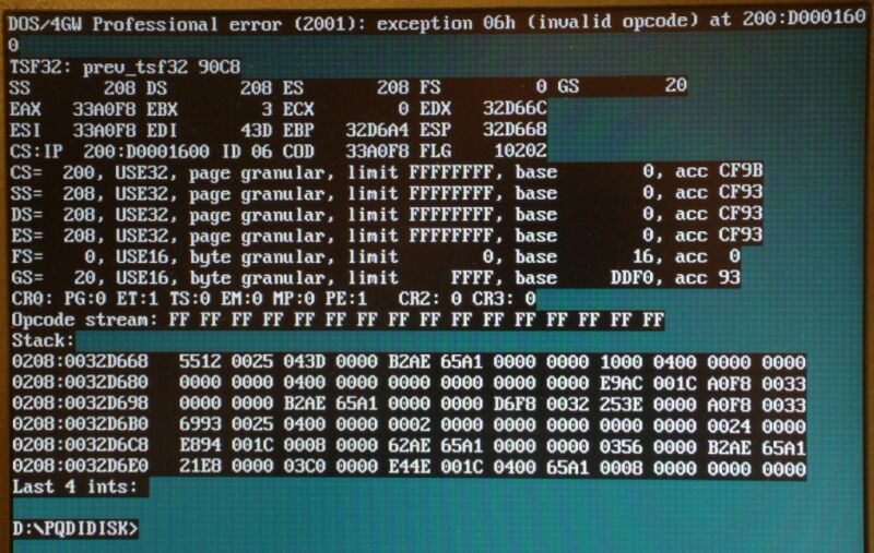
Fehlermeldung eines DOS-Programms mit Speicherabbild
error (2001): exception 06h (invalid opcode) at 200:D000160 TSF32: prev_tsf32 90C8 208 DS 208 ES 0 GS 20 SS EAX 33A0F8 EBX 3 ECX 0 EDX 32D66C ESI 33A0F8 EDI 43D6A4 ESP 32D668 CS: IP 200:D000160 ID 06 COD 33A0F8 FLG 10202 CS= 200, USE32, page granular, limit FFFFFFFF, base 0, acc CF9B SS= 208, USE32, page granular, limit FFFFFFFF, base 0, acc CF93 DS= 208, USE32, page granular, limit FFFFFFFF, base 0, acc CF93 ES= 208, USE32, page granular, limit FFFFFFFF, base 0, acc CF93 FS= 0, USE16, byte granular, limit 0, base 16, acc 0 GS= 20
in „Wie Festplatte wieder in Neuzustand versetzen“ · PC Hard- und Software · · Screenshots
-
PDF
A100_BC549x_BC550x.pdf
(T =25ºC)a DESCRIPTION SYMBOL BC549 BC550 UNITS Collector Emitter Voltage VCEO 30 45 V Collector Base Voltage VCBO 30 50 V Emitter Base Voltage VEBO 5.0 V Collector Current Continuous IC 100 mA Power Dissipation at Ta=25ºC PD 625 mW Derate Above 25ºC 5.0 mW/ºC Power Dissipation at Tc=25ºC PD 1.5 W Derate
in „Rätselhafter Transistor“ · Mikrocontroller und Digitale Elektronik ·
-
PDF
Firmware_issues.pdf
crashing and not responding anymore. 2. Apply test signal, do auto setup to trigger properly. Set time base to 4ns/DIV, change Acquisition mode from “Real Time” to “Equ Time”, hide menu by pushing F0, turn time base knob from 4ns/DIV to 2ns/DIV and DSO is crashing and not responding anymore. This bug seems
in „TEKWAY DST1xx2B Oszilloskop“ · Mikrocontroller und Digitale Elektronik ·
-
Datei
t6963c.h
glcd_FONT_WIDTH 6 // pixel width #define glcd_BYTES_PER_ROW 40 // 40 chars per row #define glcd_G_BASE 0x0400 // base address of graphics memory #else // normal font #define glcd_FONT_WIDTH 8 // pixel width #define glcd_BYTES_PER_ROW 30 // 30 chars per row #define glcd_G_BASE 0x0200 // base address of
-
Datei
t6963c.h
glcd_FONT_WIDTH 6 // pixel width #define glcd_BYTES_PER_ROW 40 // 40 chars per row #define glcd_G_BASE 0x0400 // base address of graphics memory #else // normal font #define glcd_FONT_WIDTH 8 // pixel width #define glcd_BYTES_PER_ROW 30 // 30 chars per row #define glcd_G_BASE 0x0200 // base address of
-
PDF
ttester_eng104k.pdf
In this case you should only connect two probes and start measurement again, one after the other. 20. Measurement of the capacity value of a single diode in reverse direction. Bipolar Transistors can also be analysed, if you connect the Base and only one of Collector or Emitter. 21. Only one measurement
-
PDF
MJE2955T-D.PDF
Value Unit PNP NPN Collector−Emitter Voltage VCEO 60 Vdc COLLECTOR 2, 4 COLLECTOR 2, 4 Collector−Base Voltage VCB 70 Vdc Emitter−Base Voltage V EB 5.0 Vdc Collector Current I 10 Adc 1 1 C BASE BASE Base Current IB 6.0 Adc Total Device Dissipation PD EMITTER 3 EMITTER 3 @ T C 25°C (Note 1) 75 W Derate
in „Simulation zeigt das Gegenteil der Praxis“ · Analoge Elektronik und Schaltungstechnik ·
-
Datei
T6963.c
void) { unsigned int t; for (t=0; t<1000; t++) { *RESETPtr=0; } // ca. 125æs. Reset lcd_send_data(T_BASE%256); // Text Adresse lcd_send_data(T_BASE>>8); lcd_send_cmd(0x40); lcd_send_data(BYTES_PER_ROW%256); // Zeilenlänge lcd_send_data(BYTES_PER_ROW>>8); lcd_send_cmd(0x41); lcd_send_data(G_BASE%256); /
in „Hilfe ext. Mem ATmega162“ · Mikrocontroller und Digitale Elektronik ·
-
PDF
diode-ds31634.pdf
Information: See Page 3 • Weight: 0.072 grams (approximate) T C CO LLE CTOR U 2,4 3 E D O 4 2 C 1 C R BAS E P 1 B 3 W EM TER T OP VIEW E Top View Device Schematic Pin Out Configuration N Maximum Ratings @T =A25°C unless otherwise specified Characteristic Symbol Value Unit Collector-Base Voltage V CBO -15
in „Transistor als Schalter beim Akkuladen“ · Analoge Elektronik und Schaltungstechnik ·
-
PDF
The_International_System_of_Units_sp330.pdf
12; CR, 87). practical, world-wide system of units for international relations, for teaching, The 20th CGPM (1995, Resolution 8; CR, 223 and for scientific work, decided to base the International System on a choice of and Metrologia, 1996, seven well-defined units which by convention are regarded as
in „Stromangabe in der Einheit At?“ · Mikrocontroller und Digitale Elektronik ·
-
Datei
Build_started_28.10.2008_at_15_33_50.txt
DF_CPU=14745600UL -Os -funsigned-char -funsigned-bitfields -fpack-struct -fshort-enums -MD -MP -MT base64.o -MF dep/base64.o.d -c ../base64.c avr-gcc.exe -I"D:\www\atmel\webserver\Wil\avr-webserver101\avr-webserver\." -mmcu=atmega644p -Wall -gdwarf-2 -std=gnu99 -DF_CPU=14745600UL -Os -funsigned-char -
in „AVR Studio: plugin-Error“ · Mikrocontroller und Digitale Elektronik ·
-
PDF
NAT7210_AN110.pdf
+2 #define accr BASE_ADDRESS+2 #define bsr BASE_ADDRESS+3 #define auxcr BASE_ADDRESS+3 #define isr2 BASE_ADDRESS+4 #define adr BASE_ADDRESS+4 #define spmr BASE_ADDRESS+5 #define spsr BASE_ADDRESS+5 #define cptr BASE_ADDRESS+6 #define ppr BASE_ADDRESS+6 #define dir BASE_ADDRESS+7 #define cdor BASE_ADDRESS+7 #define tauxmr BASE_ADDRESS+5 /* isr0 bits*/ #define b_int0 0x80 #define b_int1 0x40 #define b_bi 0x20 #define b_bo 0x10 37 #define b_end
in „avr und gpib“ · Mikrocontroller und Digitale Elektronik ·
-
Datei
Osram.lib.txt
*---------------------------------------------------------------* * connections: collector * * | base * * | | emitter * * | | | * * SFHXXXX Coll Base Emit * *---------------------------------------------------------------* * not all phototransistors have physical connection of the base * * the base
in „Fototransistor mit LTSpice simulieren“ · Analoge Elektronik und Schaltungstechnik ·
-
Datei
pollin-pnx8950_combined.diff
87,46 @@ pci_mem_code = IPA051_PCI_SETUP__BASExx_SIZ_16M; /* Set PCI_XIO registers */ - writel(PCIMEM_BASE, IPA051_PCI_BASE1_LO); - writel(PCIMEM_BASE + PCIMEM_SIZE + 1, IPA051_PCI_BASE1_HI); - writel(PCIIO_BASE, IPA051_PCI_BASE2_LO); - writel(PCIIO_BASE + PCIIO_SIZE + 1, IPA051_PCI_BASE2_HI); + writel(PCIMEM_BASE, IPA051 + IPA051_PCI_BASE1_LO); + writel(PCIMEM_BASE + PCIMEM_SIZE + 1, IPA051 + IPA051_PCI_BASE1_HI); + writel(PCIIO_BASE, IPA051 + IPA051_PCI_BASE2_LO); + writel(PCIIO_BASE + PCIIO_SIZE + 1, IPA051 + IPA051_PCI_BASE2_HI);
in „Pollin - Receiver-Mainboard mit Twin DVB-[T,C] Tuner, NXP PNX8950EH“ · Mikrocontroller und Digitale Elektronik ·
-
Datei
Lcd_4x20.bas
' ********************************************************************** ' ** Program name: Testboard - Version : 1.0 21.07.2004 ** ' ** Compiler : BASCOM AVR, ( V1.11.7.4) ** ' ** ATMEGA32 LCD-Board 4x20 ** ' ** ** ' ** ** ' ** Referenz Prozessor = 12.0000 MHz ** ' ** ** ' ** ** ' ** ** ' ** Written by: Sepp Bartl ** ' ********************************************************************** $regfile = "M32def.DAT" 'use the ATMEGA32 file $crystal = 12000000 '$sim 'Osccal = 201 '------------------------------------------------------------------------------- ' Startup Definitions '-----------------
in „BASCOM: große Zahlen über alle 4 Zeilen eines 4-Zeiligen L“ · Projekte & Code ·
-
Datei
DS18B20.bas
' Beispiel für das myAVR Board 1 & 2 mit LCD und 1wire Temperatursensor an Pin 5 von Port C $regfile = "m8def.dat" $crystal = 3686411 ' LCD konfigurieren Port auf Ausgabe setzten und Pin's entsprechend zuordnen Ddrd = &HFF Config Lcdpin = Pin , Db4 = Portd.4 , Db5 = Portd.5 , Db6 = Portd.6 , Db7 = Portd.7 , E = Portd.3 , Rs = Portd.2 Config Lcd = 16 * 2 ' Pin für 1wire Schnittstelle festlegen, Schnittstelle wird von BASCOM durch Software realisiert Config 1wire = Portc.5 Dim Dsid(8) As Byte ' Die Adresse meines DS1820 die ich vorher ermittelt habe Dsid(1) = &H10 : Dsid(2) = &H68 : Dsid(3) = &H17 :
in „Bascom DS18B20“ · Mikrocontroller und Digitale Elektronik ·
-
Datei
netzteil-4x20.bas
$regfile "m16def.dat" $crystal = 6000000 '------------------------------------------------------------------------------- 'LCD-Initialliesieren auf 40x4 '------------------------------------------------------------------------------- Dim ___lcdno As Bit Config Lcd = 40 * 4 Config Lcdpin = Pin , E = Portd.4 , E2 = Portd.6 , Rs = Portd.5 , Db4 = Portd.3 , Db5 = Portd.2 , Db6 = Portd.1 , Db7 = Portd.0 ___lcdno = 0 Initlcd Cls Cursor Off ___lcdno = 1 Initlcd Cls Cursor Off Deflcdchar 0 , 12 , 18 , 18 , 12 , 32 , 32 , 32 , 32 Deflcdchar 1 , 10 , 32 , 17 , 17 , 17 , 19 , 13 , 32 '-------------------
in „Problem mit Bascom und SPI“ · Mikrocontroller und Digitale Elektronik ·
-
Datei
ds18b20.bas
$regfile = "m8def.dat" $crystal = 3686400 $baud = 19200 Config 1wire = Portc.1 '##################################### Variablen Dim Max_num_ds18b20 As Byte Dim Ds18b20_id(8) As Double Dim Ds18b20tempstr As String * 6 Dim Ds18b20r(9) As Byte Dim Ds18b20temp As Word Dim I As Byte '##################################### Subs und Functions Declare Sub Init_ds18b20 Declare Sub Measure_ds18b20(byval Count As Byte) Declare Sub Read_ds18b20_id Declare Function Read_ds18b20(byval Count As Byte) As Word '##################################### Call Init_ds18b20 Call Read_ds18b20_id Do For I = 1 To Max_num_ds18b20
in „Probleme mit Temperatursensor DS18B20“ · Mikrocontroller und Digitale Elektronik ·
-
PDF
rej09b0101_16c29hm_2_.pdf
.30, 2007 page 21 of 458 REJ09B0101-0112 M16C/29 Group 2. Central Processing Unit (CPU) 2.3 Frame Base Register (FB) FB is configured with 16 bits, and is used for FB relative addressing. 2.4 Interrupt Table Register (INTB) INTB is configured with 20 bits, indicating the start address of an interrupt
in „Zeitproblem bei Softwarepwm“ · Mikrocontroller und Digitale Elektronik ·
-
Datei
main.c
Hardware initialization function. static void Initialize(void) { volatile AT91PS_PIO pPIO = AT91C_BASE_PIOA; AT91PS_PMC pPMC = AT91C_BASE_PMC; int i; // Set Flash Wait sate // Single Cycle Access at Up to 30 MHz, above (up to 55MHz): // at least 1 flash wait state. // FMCN: flash microsecond cycle number: Number of MCLK cycles in one usec. // For 20 MHz, this is 20. Value must be rounded up. AT91C_BASE_MC->MC_FMR = ((AT91C_MC_FMCN)&(22 <<16)) | AT91C_MC_FWS_0FWS; // Disable watchdog. AT91C_BASE_WDTC->WDTC_WDMR= AT91C_WDTC_WDDIS; // After reset,
in „arm-elf-ld problem, undefined reference to `__gccmain'“ · µC & Digital Electronics ·
-
PDF
Arcam-FMJ-P7.pdf
25A per channel Total harmonic distortion At any level up to rated power, into 4 or 8 ohms <0.05% (20Hz – 20kHz) Typically <0.005% at 1kHz Frequency response +-0.2dB (20Hz – 20 kHz) -1dB at 1Hz and 100kHz Residual hum and noise Referenced to full power -122dB, 20Hz – 20kHz, unweighted Voltage gain x
in „Bandbreite von analogen Audioschaltungen“ · Analoge Elektronik und Schaltungstechnik ·
-
PDF
Arcam-FMJ-P7.pdf
25A per channel Total harmonic distortion At any level up to rated power, into 4 or 8 ohms <0.05% (20Hz – 20kHz) Typically <0.005% at 1kHz Frequency response +-0.2dB (20Hz – 20 kHz) -1dB at 1Hz and 100kHz Residual hum and noise Referenced to full power -122dB, 20Hz – 20kHz, unweighted Voltage gain x
in „Bester Audio OPV“ · Analoge Elektronik und Schaltungstechnik ·
-
PDF
CD4528.PDF
BSC 0.050 BSC J 0.19 0.25 0.008 0.009 C K 0.10 0.25 0.004 0.009 −T− M 0_ 7_ 0_ 7_ SEPLANE P 5.80 6.20 0.229 0.244 M J R 0.25 0.50 0.010 0.019 D 16 PL 0.25 (0.010) M T B S A S STYLE 1: STYLE 2: STYLE 3: STYLE 4: PIN 1. COLLECTOR PIN 1. CATHODE PIN 1. COLLECTOR, DYE #1 PIN 1. COLLECTOR, DYE #1 2. BASE
in „Unterschied CD4528 zu CD4538 ?“ · Mikrocontroller und Digitale Elektronik ·
-
PDF
A100_bc546_48.pdf
UNITS Collector Emitter Voltage VCEO 65 45 30 V Collector Emitter Voltage VCES 80 50 30 V Collector Base Voltage V 80 50 30 V CBO Emitter Base Voltage VEBO 6 6 5 V Collector Current Continuous IC 100 mA Collector Current Peak CM 200 mA Base Current Peak IBM 200 mA Emitter Current Peak IEM 200 mA Power
in „Hallo möchte Schaltung nachbauen.“ · Mikrocontroller und Digitale Elektronik ·
-
PDF
Transistor_BC547C_NPN_TO-92_45V_0_1A_0_5W.pdf
UNITS Collector Emitter Voltage VCEO 65 45 30 V Collector Emitter Voltage VCES 80 50 30 V Collector Base Voltage V 80 50 30 V CBO Emitter Base Voltage VEBO 6 6 5 V Collector Current Continuous IC 100 mA Collector Current Peak CM 200 mA Base Current Peak IBM 200 mA Emitter Current Peak IEM 200 mA Power
in „Hilfe bei transistor auswahl/suche“ · Analoge Elektronik und Schaltungstechnik ·
-
PDF
BC546_48-CDIL.pdf
UNITS Collector Emitter Voltage VCEO 65 45 30 V Collector Emitter Voltage VCES 80 50 30 V Collector Base Voltage V 80 50 30 V CBO Emitter Base Voltage VEBO 6 6 5 V Collector Current Continuous IC 100 mA Collector Current Peak CM 200 mA Base Current Peak IBM 200 mA Emitter Current Peak IEM 200 mA Power
in „Defekt an elektronischer Bremse einer Kreissäge.“ · Analoge Elektronik und Schaltungstechnik ·
-
PDF
AN_1293_A_Comparison_of_BJT_Biasing__Avago.pdf
of the emitter base voltageV .BE [3. IBB+ B RB1 B IB C C VBE hie VCE BB RC VBE hFE B CBO(1 +FE ) RB2 CC E Figure 2. Gummel Poon model of BJT withVoltage Feedback and Constant Base Current Source Network BJTModeling The
in „"Active biasing" bei HF-Transistoren“ · HF, Funk und Felder ·
-
Datei
lib_AT91SAM7S256.h
AT91F_SSC_CfgPIO (void) { // Configure PIO controllers to periph mode AT91F_PIO_CfgPeriph( AT91C_BASE_PIOA, // PIO controller base address ((unsigned int) AT91C_PA19_RK ) | ((unsigned int) AT91C_PA16_TK ) | ((unsigned int) AT91C_PA15_TF ) | ((unsigned int) AT91C_PA18_RD ) | ((unsigned int) AT91C_PA20
in „C Datein werden in Eclipse nicht kompiliert“ · Mikrocontroller und Digitale Elektronik ·
-
Datei
pinaddr.c
bekommen die Adresse im RAM für den jeweiligen PIN ( also 0x30 fuer PIND, 0x33 fuer PINC,...) #define pinBaseAddr(pa) ( (((pa) >> 3) & 3) * 3 + 0x10 + 0x20) // Die Adresse fuer das PIN-Register ist genau die pinBaseAddr (s.o.) // Die Adresse fuer das DDR-Register ist die pinBaseAddr + 1 // Die Adresse fuer das PORT-Register ist die pinBaseAddr + 2 #define pinPinAddr(pa) pinBaseAddr(pa) #define pinDdrAddr(pa) (pinBaseAddr(pa) + 1) #define pinPortAddr(pa) (pinBaseAddr(pa) + 2) // Die Bit-Nummer aus einer Pin-Adresse extrahieren ( Bits 0
in „Ports in Array möglich?“ · Mikrocontroller und Digitale Elektronik ·
-
Datei
servo1.c
; case 'x': base = 16; CONVERSION_LOOP: u_val = va_arg(ap,int); ptr = scratch + SCRATCH; *--ptr = 0; do { char ch = u_val % base + '0'; if (ch > '9') ch += 'a' - '9' - 1; *--ptr = ch; u_val /= base; } while (u_val);
in „code für Servo Signal Fehler“ · Mikrocontroller und Digitale Elektronik ·
-
PDF
JSMSEMI-S8050.pdf
K J MAXIMUM RATINGS (T A=25 Cunless otherwise noted) Symbol Parameter Value Units V CBO Collector-Base Voltage 40 V V CEO Collector-Emitter Voltage 25 V V EBO Emitter-Base Voltage 5 V IC Collector Current -Continuous 0.5 A P C Collector Dissipation 0.3 W Tj Junction Temperature 150 ℃ Tstg Storage Temperature
in „Relaischaltung entwerfen“ · Mikrocontroller und Digitale Elektronik ·
-
PDF
Vorab_die_Lernbetty.pdf
Al- lerdings sind die 2 Lanes des Videopuffers im Startup- Die simplen kleinen Menüs in der BettyBase hab ich per Script gemacht, entsprechend formal sieht es von innen code festgelegt. Das hat den Vorteil, daß man auch au- aus. Es wäre wesentlich besser, sich dafür einen grafi- ßerhalb von BettyBase
in „die Betty-Fernbedienung von Pollin als ARM-Eval Board“ · Mikrocontroller und Digitale Elektronik ·
-
Datei
system.h
5.5 #define SDRAM_CTRL_T_MRD 3 #define SDRAM_CTRL_T_RCD 20.0 #define SDRAM_CTRL_T_RFC 70.0 #define SDRAM_CTRL_T_RP 20.0 #define SDRAM_CTRL_T_WR 14.0 /* * System configuration * */ #define ALT_DEVICE_FAMILY "Cyclone IV E" #define ALT_ENHANCED_INTERRUPT_API_PRESENT #define ALT_IRQ_BASE NULL #define ALT_LOG_PORT "/dev/null" #define ALT_LOG_PORT_BASE 0x0 #define ALT_LOG_PORT_DEV null #define ALT_LOG_PORT_TYPE "" #define ALT_NUM_EXTERNAL_INTERRUPT_CONTROLLERS 0 #define ALT_NUM_INTERNAL_INTERRUPT_CONTROLLERS
in „Altera Cyclone IV - Registeradressen finden“ · FPGA, VHDL & Co. ·
-
PDF
XLamp7090XR-E.pdf
Power )100 ( r 80 e w o t 60 5000K - 10000K CCT n i 3700K - 5000K CCT d 40 2600K - 3700K CCT R v t 20 l e R 0 400 450 500 550 600 650 700 750 Wavelength (nm) White ) 100 ( r 80 e w o t 60 Royal Blue n Blue i d 40 Green R v t 20 l e R 0 400 450 500 550 600 650 Wavelength (nm) Color Relative Flux Output
in „LiPo Zelle Impulsbelastung“ · Mikrocontroller und Digitale Elektronik ·
-
PDF
S8050_J3Y.pdf
SOT-23 MAXIMUM RATING @ Ta=25℃ unless otherwise specified Symbol Parameter Value Units V Collector-Base Voltage 40 V CBO VCEO Collector-Emitter Voltage 25 V VEBO Emitter-Base Voltage 5 V I Collector Current -Continuous 500 mA C PC Collector Dissipation 300 mW Tj, stg Junction and Storage Temperature -
in „ESP LED PWM Ansteuerung mit Transistor“ · Mikrocontroller und Digitale Elektronik ·
-
PDF
mosfet.pdf
reverse base drive Device Symbol. currents are required to obtain fast turn-off. Despite the very advanced state of manufacturability and lower costs of BJTs, these limitations have made the base drive circuit design
in „MOSFET - welche Leistung?“ · Analoge Elektronik und Schaltungstechnik ·
-
PDF
mosfet.pdf
reverse base drive Device Symbol. currents are required to obtain fast turn-off. Despite the very advanced state of manufacturability and lower costs of BJTs, these limitations have made the base drive circuit design
in „NT mit Mosfet“ · Analoge Elektronik und Schaltungstechnik ·
-
PDF
Mosfet-Basics-IR.pdf
reverse base drive Device Symbol. currents are required to obtain fast turn-off. Despite the very advanced state of manufacturability and lower costs of BJTs, these limitations have made the base drive circuit design
in „MOSFET Sättigung“ · Analoge Elektronik und Schaltungstechnik ·
-
Datei
BLOWIT.PAS
; {read and concert the file} writeln('Programming '+chip+' on Port: ',c); write('Erasing'); port[base] := $FF; { Erase } port[base+2] := $01; nms(2{10}); port[base+2] := $03; { RST = 12 } nms(1); port[base+2] := erase_mode; { RST = 12, PROG = H } nms(1); write('.'); port[base+2] := erase_mode xor prog_bit; { P3.2 = 0 } nms(3{12}); { This is ERASE PULSE!} write('.'); port[base+2] := erase_mode; { P3.2 = 1 } nms(3{12}); write('.'); port[base+2] := erase_mode xor vpp_bit; { RST = 0 } nms(5{20}); write('.'); { Program ROM } port[base+2] := idle; nms(2{10}); port[base+2] := idle
-
Datei
pio_uart_rx_restart_test.py
self.statemachine = statemachine self.active(1) def _restart(self): # userdefined statemachine.restart() PIO_BASE = 0x5020_0000 if self.statemachine & 0x04: # PIO0 or PIO1 ? PIO_BASE = 0x5030_0000 sm = self.statemachine & 0x03 ctrl_reg = mem32[PIO_BASE] # read CTRL-Register # ctrl_reg |= (1 << sm) # enable Bit
in „8 UART's mit asm_pio / PIO / DMA / Micropython auf dem PI PICO“ · Projekte & Code ·
-
PDF
BCR48.pdf
SOT-363 Maximum Ratings Parameter Symbol Values Unit Collector-emitter voltage VCEO 50 V Collector-base voltage V 50 CBO Emitter-base voltage NPN VEBO 10 Emitter-base voltage PNP VEBO 5 DC collector current NPN I 70 mA C DC collector current PNP C 100 Input on voltage NPN Vi(on) 50 V Input on voltage
in „Frage zu Bauelement BCR48 (NPN und PNP Transistor)“ · Analoge Elektronik und Schaltungstechnik ·
-
Datei
main.c
PrescalerValue = (uint16_t) 36000 - 1; // Vorteiler berechnen (36Mhz/36000 = 1khz) TIM_TimeBase_InitStructure.TIM_Prescaler = PrescalerValue; // TIM_TimeBase_InitStructure.TIM_ClockDivision = TIM_CKD_DIV1; // nach Prescaler=1kHz TIM_TimeBase_InitStructure.TIM_CounterMode = TIM_CounterMode_Up; TIM_TimeBase_InitStructure.TIM_Period = 1000; // Eine Sekunde (=1000*1kHz=1s) TIM_TimeBaseInit(TIM2, &TIM_TimeBase_InitStructure); //Timer Vorteiler-Taktkonfiguration // TIM_PrescalerConfig(TIM2, PrescalerValue,
in „STM32 : Float linken mit Coocox“ · Mikrocontroller und Digitale Elektronik ·
-
PDF
bux87.pdf
VCES Collector-emitter voltagBE= 0) 1000 V VCEO Collector-emitter voltaBe (I = 0) 450 V VEBO Emitter-base voltageC(I = 0) 5 V IC Collector current 0.5 A ICM Collector peak currenp (t ≤ 5ms) 1 A IB Base current 0.3 A I Base peak current (t ≤ 5ms) 0.6 A BM p P Total power dissipation at T = 25 °C 40 W TOT
in „Hochspannung Regeln für eine Bildverstärker Röhre“ · Analoge Elektronik und Schaltungstechnik ·
-
Datei
main.c
Digital_IN = Digital_IN | 0x40; } if(AT91C_BASE_PIOA->PIO_PDSR & PA27){ Digital_IN = Digital_IN | 0x20; } if(AT91C_BASE_PIOA->PIO_PDSR & PA26){ Digital_IN = Digital_IN | 0x10; } if(AT91C_BASE_PIOA->PIO_PDSR & PA25){ Digital_IN = Digital_IN | 0x08
in „TWI und AT91SAM7S“ · Mikrocontroller und Digitale Elektronik ·
-
Datei
OneWire.c
= 0 ; i < count ; i++) OneWire__write(buf[i], 0); if (!power) { noInterrupts(); DIRECT_MODE_INPUT(baseReg, bitmask); DIRECT_WRITE_LOW(baseReg, bitmask); interrupts(); } } // // Write a byte. The writing code uses the active drivers to raise the // pin high, if you need power after the write (e.g. DS18S20
in „Böses One-Wire device“ · Mikrocontroller und Digitale Elektronik ·
-
PDF
2N3906.pdf
) Collector-Emitter Saturation Voltage C = 10 mA, IB= 1.0 mA 0.25 V C = 50 mA, IB= 5.0 mA 0.4 V V Base-Emitter Saturation Voltage I = 10 mA, I = 1.0 mA 0.65 0.85 V BE(sat) C B C = 50 mA, IB= 5.0 mA 0.95 V SMALLSIGNALCHARACTERISTICS fT Current Gain - Bandwidth Product IC= 10 mA, V CE= 20 V, 250 MHz f
in „SMD version vom 2n3906 / 2n3904“ · Mikrocontroller und Digitale Elektronik ·
-
Datei
lcd.c
switch (by) { case 's': ptr = va_arg(ap,char *); while(*ptr) {lcd_write(*ptr++,1); } break; case 'b': Base = 2; goto ConversionLoop; case 'c': //Int to char format_flag = va_arg(ap,int); lcd_write (format_flag++,1); break; case 'i': Base = 10; goto ConversionLoop; case 'o': Base = 8; goto ConversionLoop; case 'x': Base = 16; //**************************** ConversionLoop: //**************************** itoa(va_arg(ap,int),str_buffer,Base); int b=0; while (str_buffer[b++] != 0){}; b--; if (b<move) { move -=b; for (tmp
in „Serielles Display“ · Mikrocontroller und Digitale Elektronik ·
-
PDF
spma014.pdf
Comparison of Variable Sizes Locals of size int Locals of size short int (half word) typedef int BASE; typedef short BASE; BASE foo(BASE last, BASE x, BASE y) BASE foo(BASE last, BASE x, BASE y) { { 0: 2300 movs r3, #0 0: f04f 0c00 mov.w ip, #0; 0x0 2: e002 b.n a <foo+0xa> 4: e004 b.n 10 <foo+0x10>
in „ARM Cortex & GCC: Worauf achten für "optimalen" Code?“ · Mikrocontroller und Digitale Elektronik ·
-
PDF
Siedle_HTS811_SET_CA_812-x_EW_210008862-00_PI--.pdf
call as 2-tone call in and insert the cores into the base Compact set with ZERT 811-0 pos- Electrostatic charging plate. Fasten the base plate using 4 sible screws. Close the two openings at • Integrated call silencing via volume the top using rubber stoppers
in „Klingel mit 100 Melodien - last minute Weihnachtsgeschenk“ · Projekte & Code ·