-
Datei
myfirst168.s
spectrum clock generation register .set RCC_PLLI2SCFGR, 0x84 @ RCC I2S PLL configuration register @ USART3 on STM32F4 chips: @ USART3 on STM32F1/STM32F4 chips: pp. 1018 in RM0090 (dm00031020-stm*.pdf) .equ UART3 , 0x40004800 .equ UART3_SR , 0x00 .equ USART3
in „Break auf 0xfffffffe in STM32CubeIDE“ · Mikrocontroller und Digitale Elektronik ·
-
Datei
myfirst168.s
spectrum clock generation register .set RCC_PLLI2SCFGR, 0x84 @ RCC I2S PLL configuration register @ USART3 on STM32F4 chips: @ USART3 on STM32F1/STM32F4 chips: pp. 1018 in RM0090 (dm00031020-stm*.pdf) .equ USART3_BASE , 0x40004800 .equ USART3_SR , USART3_BASE
in „STM32CubeIDE - kann man dem gdb server einen Schalter mitgeben?“ · Mikrocontroller und Digitale Elektronik ·
-
Datei
spi2_slave.h
//-------------------------------------------------------------- // File : stm32_ub_spi2_slave.h //-------------------------------------------------------------- //-------------------------------------------------------------- #ifndef __SPI2_SLAVE_H #define __SPI2_SLAVE_H //--
in „RaspberryPI <- SPI -> STM32F4“ · Mikrocontroller und Digitale Elektronik ·
-
Datei
i2c_stm32f10x.c
die Hardware-Adressen direkt hinterlegt werden. * * Erzeugt: 31.03.2014 * Author: Nicolas */ #ifndef STM32F10x #error "only STM32F10x supported" #endif #include "stm32f10x_gpio.h" #include "stm32f10x_rcc.h" #include "stm32f10x_i2c.h" #include "../src_misc/clock.h" // glu_millis #include "../../main.h"
in „STM32F10x : Fehler bei I2C“ · Mikrocontroller und Digitale Elektronik ·
-
PDF
picomon_v3.pdf
und linkt alle benötigten Programmteile zu einer flashbaren Binärdatei ◦ Hinweis: Im Makefile für STM32F0xx kann/muß der Controller korrekt gewählt sein, um ggf. den erhöhten RAM-Bedarf des Programms bedienen zu können, für LSCRIPT steht zur Verfügung: stm32f030x4.ld , stm32f030x6.ld , stm32f030x8.ld , stm32f070x6.ld , stm32f042x6.ld • picomon.c ◦ Quellcode und Main-Programm der Firmware • spi_tft.c ◦ Quellcode zur Ansteuerung der internen Hardware-SPI, sendet Daten vom Controller zum Display • spi_tft.h
in „PicoMon für CH32V003 oder STM32F0xx“ · Projekte & Code ·
-
Datei
main.c
#include "stm32f4xx.h" #include "system_stm32f4xx.h" #include "stm32f4xx_gpio.h" #include "stm32f4xx_rcc.h" #include "stm32f4xx_tim.h" #include "misc.h" int main(void) { SystemInit(); // Initialize the GPIO / LEDs
in „[STM32F407VG, Discovery-board] Timer-interrupt verwirrt mich“ · Mikrocontroller und Digitale Elektronik ·
-
Datei
main.c
// Simple GPIO Example for STM32F10x und STM32F30x Discovery Modul Juni 2013 // A.Schnell #include "stm32f30x.h" #include "stm32f30x_gpio.h" #include "stm32f30x_rcc.h" #define BUTTON GPIO_Pin_0 // User Button #define LED6 GPIO_Pin
in „AVR ARM STM32F3 Discovery GPIO Einführung“ · Projekte & Code ·
-
Datei
main.c
main.h" #include "io.h" #include "hw_config.h" #include "sw_config.h" #include "hw_config.h" #include "stm32f4xx_conf.h" #include "usart.h" #if defined( STM32F10x ) || defined( STM32F4XX ) /* Zielplattform (Debug, Release, Modultests) */ #define MAINFUN int main(void) #else #error "unknown platform" #endif
in „STM32F446: USART DMA-Transfer“ · Mikrocontroller und Digitale Elektronik ·
-
Datei
main.c
#include "stm32f4xx.h" #include "stm32f4xx_conf.h" #include "stm32_ub_usb_cdc.h" #include "stm32_ub_led.h" #include "stm32_ub_adc1_single.h" #include <stdio.h> int main(void){ char buf[APP_TX_BUF_SIZE]; USB_CDC_RXSTATUS_t
in „STM32F4 sprintf mit float“ · Mikrocontroller und Digitale Elektronik ·
-
PDF
ArmAssemblerTutorial.pdf
customary to name the linker script after the controller they are intended for, so create a text file “stm32f103rb.ld” or “stm32f103c8.ld” with the following contents: MEMORY { FLASH : ORIGIN = 0x8000000, LENGTH = 128K SRAM : ORIGIN = 0x20000000, LENGTH = 20K } SECTIONS { .text : { *(.text) } >FLASH .data
in „ARM-Assembler-Tutorial“ · Mikrocontroller und Digitale Elektronik ·
-
Datei
main.c
---- // Hardware : STM32F4 Discovery // Takt : 53,76 MHz // Sprache : ARM C // Datum : 08.12.2013 // Version : 1 // Autor : nicolas //---------------------------------------------------------------------- #include <stddef.h> #include <stdlib.h> //#include "stm32f4xx.h" #include "stm32f4xx_gpio.h" #include "stm32f4xx_rcc.h" #include "stm32f4xx_tim.h" #include "misc.h" void initApplication(void) { SysTick_Config(SystemCoreClock/100); RCC_AHB1PeriphClockCmd(
in „Anfängerfrage STM32“ · Mikrocontroller und Digitale Elektronik ·
-
Datei
http.cpp
uint_fast8_t rtc = 0; flash_stm32_filename[0] = '\0'; sv = get_strvar (VERSION_STR_VAR); version = sv->str; #if 0 hardware_configuration = get_numvar (HARDWARE_CONFIGURATION_NUM_VAR); switch (hardware_configuration & HW_STM32_MASK) { case HW_STM32F103: stm32_filename_idx = 0; break; case HW_STM32F401: stm32_filename_idx = 1; break; case HW_STM32F411: stm32_filename_idx = 2; break; } switch (hardware_configuration & HW_WC_MASK) { case HW_WC24H
-
Datei
main.c
---------------------*/ #define USE_STDPERIPH_DRIVER #include "main.h" #include <math.h> #include <stm32f4xx.h> #include <misc.h> // I recommend you have a look at these in the ST firmware folder #include <stm32f4xx_spi.h> // under Libraries/STM32F4xx_StdPeriph_Driver/inc and src #include <stm32f4xx_rcc.h> #include <stdint.h> #include "stm32f4xx_conf.h" #include "usart.h" #include "dprintf.h" #include "common.h" //#include "tabellen.h" USART_TypeDef* USARTx = USART1; volatile uint8_t stopsampling=0; volatile uint32_t timercnt=0; volatile
in „Hook up a MEMS microphone to the I2S of a Cortex M4“ · Projekte & Code ·
-
Datei
stm32.ld
project here. */ /* include the common STM32F10x sub-script */ INCLUDE "STM32_COMMON.ld" /* Memory Spaces Definitions */ MEMORY { RAM (xrw) : ORIGIN = 0x20000000, LENGTH = 20K /* also change _estack below */ FLASH (rx) : ORIGIN = 0x8000000,
in „J-Link EDU + Eclipse + STM32-H103 Board debugging problem“ · Mikrocontroller und Digitale Elektronik ·
-
Datei
stm32f107.c
/** ****************************************************************************** * @file stm32f107.c * @author MCD Application Team * @version V1.0.0 * @date 11/20/2009 * @brief STM32F107 hardware configuration ****************************************************************************** *
in „lwIP 1.4.1 + freeRTOS 8.2.3 + stm32f107vb“ · Mikrocontroller und Digitale Elektronik ·
-
PDF
_ATT_12740.pdf
, which sends CAN messages and receives CAN messages Hardware setup CAN bus PC terminal analyzer STM32L476G-EVAL STM32CubeMX Selecting CAN interface and clock • Create project in STM32CubeMX • Menu > File > New Project • Select STM32L4 -> STM32L4x6 -> LQFP144 package -> STM32L476ZGTx • Select CAN:
in „STM32 CAN Botschaft empfangen“ · Mikrocontroller und Digitale Elektronik ·
-
Datei
main.c
#include "stm32f0xx.h" #include "stm32f0xx_gpio.h" #include "stm32f0xx_rcc.h" #include "stm32f0xx_tim.h" #include "stm32f0xx_misc.h" #include <stdlib.h> #include <stddef.h> #include <math.h> void init_Timer(void)
in „stm32f030f4p6 PWM“ · Mikrocontroller und Digitale Elektronik ·
-
PDF
MCP2307_IO_Expansion_Board_User_Manual_EN.pdf
Arduino Uno STM32F407 Raspberry Pi Vcc Voltage 3.3V/5V 3.3V/5V 3.3V/5V GND Ground GND GND GND SDA I2C data line SDA PB7 SDA SCL I2C clock line SCL PB6 SCL INTA 1 Interrupt pin 3 PA0 0(WiringPi) INTB 2 Interrupt pin
in „kennt jemand sich aus mit MC23017 IO-Board“ · Mikrocontroller und Digitale Elektronik ·
-
Datei
irmp.c
(1<<URSEL) #else #define UART0_URSEL_BIT_VALUE (0) #endif #define UART0_TXEN_BIT_VALUE (1<<TXEN) #define UART0_UDR UDR #define UART0_U2X U2X #endif //UBRR0H #endif //IRMP_EXT_LOGGING #endif //ARM_STM32F4XX /*----------------------
in „IRMP - Infrared Multi Protocol Decoder“ · Projekte & Code ·
-
Datei
irmp.c
(1<<URSEL) #else #define UART0_URSEL_BIT_VALUE (0) #endif #define UART0_TXEN_BIT_VALUE (1<<TXEN) #define UART0_UDR UDR #define UART0_U2X U2X #endif //UBRR0H #endif //IRMP_EXT_LOGGING #endif //ARM_STM32F4XX /*----------------------
in „IRMP - Infrared Multi Protocol Decoder“ · Projekte & Code ·
-
Datei
usb_vcp.c
h> CORE params // <o> UMEMSHIFT <0=> off // <1=> on // <i> Off for devices with 2 x 16 bits / uint16_t access schema // <i> e.g. STM32L0x2, STM32L0x3, STM32F0x2, STM32F303xD and xE // <i> On for devices with 1 x 16 bits / uint16_t access schema // <i> e.g. STM32F103, STM32F302, STM32F303xB and xC // ********************************************************* #define UMEM_SHIFT 1 // ********************************************************* // <o> USB_IRQ_NUMBER
in „STM32 USB Übertragungsproblem mit Code von S.F.“ · Mikrocontroller und Digitale Elektronik ·
-
 Bild
Bild
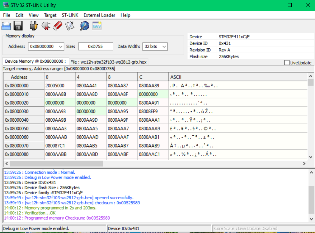
STM32 ST-LINK Utility Speicheranzeige
STM32 ST-LINK Utility Device STM32F411xC/E Device ID 0x431 Revision A Flash size 256KBytes Address: 0x08000000 Size: 0xD755 Data Width: 32 bits Device Memory @ 0x08000000 File: [wc12h-stm32f103-ws2812-grb.hex
in „WordClock mit WS2812“ · Projekte & Code · · Screenshots
-
Datei
Usart.c
reserved. *----------------------------------------------------------------------------*/ #include <stm32f10x_lib.h> // STM32F10x Library Definitions #include <stdio.h> #include "STM32_Init.h" // STM32 Initialization /*---------------------------------------------------------------------------- Notes:
in „UART Ring Buffer volatile?“ · Mikrocontroller und Digitale Elektronik ·
-
Datei
C-Aktuell_14_07.txt
#include <stm32f10x_lib.h> // STM32F10x Library Definitions #include "STM32_Init.h" // STM32 Initialization int temp; int s; //schwarz int sz; //schwarz zucker int w; //weiß int wz; //weiß zucker int kg; //kaffee
in „Funktionsaufruf ARM“ · Mikrocontroller und Digitale Elektronik ·
-
Datei
compiler_options.txt
<Build> <Target title="elGe_Debug"> <Option output="bin\Debug\Firmware_STM32F446.elf" /> <Option object_output="obj\Debug\" /> <Option type="0" /> <Option create_hex="1" /> <Option compiler="armgcc_eb" /> <Option projectDeviceOptionsRelation="0" /> <Compiler> <Add option="
in „Böse Falle Boolean“ · Mikrocontroller und Digitale Elektronik ·
-
Datei
tools.c
stdbool.h> #include <stdint.h> /* --------------- Special Include Files / Librarys ------ */ #include "tm_stm32f4_rtc.h" #include "tm_stm32f4_disco.h" #include "tm_stm32f4_nrf24l01_cj.h" #include "tm_stm32f4_rtc.h" #include "tm_stm32f4_bmp180.h" #include "tm_stm32f4_delay.h" /* -------------- Projekt Include
in „Organisation der Header und Includes“ · Mikrocontroller und Digitale Elektronik ·
-
Datei
spi1.c
-----------------------------------------------*/ #include "stdio.h" #include "stdint.h" #include "stm32f4xx.h" #include "stm32f4xx_gpio.h" #include "stm32f4xx_spi.h" #include "stm32f4xx_rcc.h" #include "stm32f4xx_dma.h" #include "spi1.h" /** @addtogroup SPI1 * @{ */ // these two bytes are dummy bytes
in „STM32 SPI Init“ · Mikrocontroller und Digitale Elektronik ·
-
Datei
f_mess.c
/* STM32F407 Beispielprogramm für Frequenz- und Pulsweitenmessung an PC6 mit Timer 8. Das Ergebnis wird 6-stellig mit typ. 3 Mess./s oder minimal 1 Periodendauer auf einem LCD-Modul in der 1. Zeile angezeigt
in „Frequenz- und Pulsweitenmessung mit STM32F407“ · Projekte & Code ·
-
PDF
Pinout.pdf
PC13 to PC15 in output mode is limited: - The speed should notexceed 2MHz witha maximum loadof 30 pF. - These GPIOs must not be usedas currentsources (e.g. to drive an LED). 2. This feature is available on STM32F030x6 and STM32F030x4 devices only. 3. This feature is available on STM32F030x8 devices only. 4. For STM32F030x4/6/8 devices only. 5. For STM32F030xC devices only. 6. On LQFP32 package, PB2 and PB8 should be treated as unconnected pins (even when they are not available on the package, they are not forced
in „µC für n00bs“ · Mikrocontroller und Digitale Elektronik ·
-
Datei
stm32f10x_it.c
************************************************************************** * @file USART/Interrupt/stm32f10x_it.c * @author MCD Application Team * @version V3.4.0 * @date 10/15/2010 * @brief Main Interrupt Service Routines. * This file provides template for all exceptions handler and peripherals * interrupt
in „Stm32: Übertragungsfehler bei dauerhafter Übertragung“ · Mikrocontroller und Digitale Elektronik ·
-
Datei
usb_vcp.c
h> CORE params // <o> UMEMSHIFT <0=> off // <1=> on // <i> Off for devices with 2 x 16 bits / uint16_t access schema // <i> e.g. STM32L0x2, STM32L0x3, STM32F0x2, STM32F303xD and xE // <i> On for devices with 1 x 16 bits / uint16_t access
in „STM32 USB Übertragungsproblem mit Code von S.F.“ · Mikrocontroller und Digitale Elektronik ·
-
Datei
main.c
to enable both Overcurrent protection and LCD UI." #endif #define FIRMWARE_VERS "STM32 FOC SDK\0Ver.3.3.0" const char s_fwVer[32] = FIRMWARE_VERS; #ifdef __GNUC__ /* With GCC/RAISONANCE, small printf (option LD Linker->Libraries->Small printf set to 'Yes') calls __io_putchar() */ #define
in „STM32F4 - CAN1 empfängt nichts“ · Mikrocontroller und Digitale Elektronik ·
-
Datei
main.c
#include "STM32F10x.h" #include <stm32f10x_rcc.h> #include <stm32f10x_gpio.h> #include <misc.h> #define zucSTM 1 #define zuc_STM 1 #define xF_DELAY 6536//72MHZ #define F_IR 245//82// #define use_spi_tft 0 #define
in „stm32f103 mit usb-stick“ · Mikrocontroller und Digitale Elektronik ·
-
Datei
main.c
/* einfache WQVGA-TFT-Ansteuerung mit STM32F4 480x270 mit 64 Farben Der Bildspeicher liegt im internen RAM (128k), der mit höchster Geschwindigkeit beschrieben werden kann. Die Ausgabe des Bildes erfolgt per DMA über das FSMC-Interface, wobei
in „TFT-direct-drive, WQVGA-TFT an STM32F4“ · Projekte & Code ·
-
 Bild
Bild
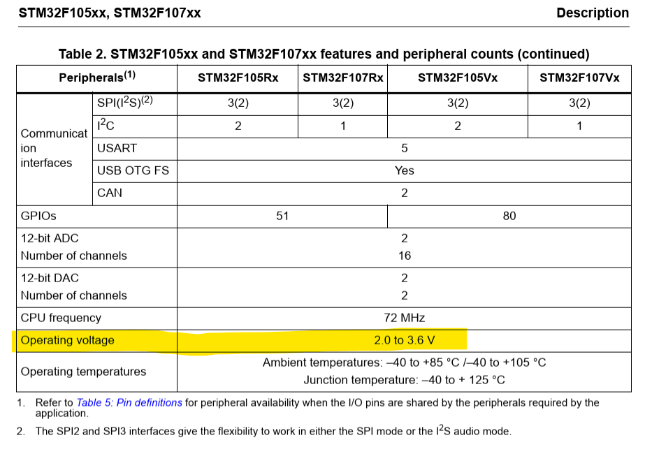
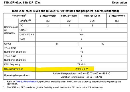
Tabelle mit STM32F105xx und STM32F107xx Merkmalen
Table 2. STM32F105xx and STM32F107xx features and peripheral counts (continued) Peripherals(1) STM32F105Rx STM32F107Rx STM32F105Vx STM32F107Vx SPI(I2S)(2) 3(2) 3(2) 3(2) Communication interfaces I2C 2 1 2 1 USART
in „Beschaltung VICOM DM9161CEP“ · Mikrocontroller und Digitale Elektronik · · Screenshots
-
PDF
MiniF4x1Cx_V31.pdf
BAT54C STM32F4X1CXU6 P0 SW33 1 3 PB2 PIW301 PSW303 3.3V LO1 PIW302 PSW3 40 PL12 PIL11 3.3V NRST 3*4 按键 GND 1KΩ 100Mhz RTC 电源 CO3 PC301 PIC02 BOOT 设置 RTC circuit BOOT Settings 0.1uF 3.3V VREF+ 复位电路 P0 PI P1 P7
in „was kommt nach dem Bluepill-Board?“ · Mikrocontroller und Digitale Elektronik ·
-
Datei
ssi_cgi_handle.c
**** */ /* Includes ------------------------------------------------------------------*/ #include "stm32f10x.h" #include "lwip/debug.h" #include "httpd.h" #include "lwip/tcp.h" #include "fs.h" ///#include "main.h" #include <stdio.h> #include <string.h> #include <stdlib.h> u8 LED1 = 0; u8 LED2 = 0; u8
in „LWIP Webserver“ · Mikrocontroller und Digitale Elektronik ·
-
Datei
User_Setup.h
#define NUCLEO_64_TFT //#define NUCLEO_144_TFT // STM32 8 bit parallel only: // If STN32 Port A or B pins 0-7 are used for 8 bit parallel data bus bits 0-7 // then this will improve rendering performance by a factor of ~8x //#define STM_PORTA_DATA_BUS
in „Powerpins am ESP32-DevKitC, WDT_RTC_RESET“ · Mikrocontroller und Digitale Elektronik ·
-
Datei
main.cpp
**** */ /* Includes ------------------------------------------------------------------*/ #include "stm32f4xx.h" #include "stm32f4xx_conf.h" /** @addtogroup STM32F4xx_StdPeriph_Examples * @{ */ /** @addtogroup GPIO_IOToggle * @{ */ /* Private typedef ---------------------------------------------------
in „Stm32f4 UART löst kein receive Interrupt aus“ · Mikrocontroller und Digitale Elektronik ·
-
Datei
stm32f2xx_rcc.h
/** ****************************************************************************** * @file stm32f2xx_rcc.h * @author MCD Application Team * @version V1.0.0 * @date 18-April-2011 * @brief This file contains all the functions prototypes for the RCC firmware library. ****************************
in „STM32F2xx USART weigert sich“ · Mikrocontroller und Digitale Elektronik ·
-
PDF
FK723M1-ZGT6.zh-CN.en.pdf
PF15 55 PF15 SCCB_SDA - PF15 STM32H723ZE/G 0.1uF BAT54C_KL3 PC1 27 PC1 PC2_C 28 56 PG0 PC3_C 29 PC2_C PG0 57 PG1 GND PC4 44 PC3_C PG1 87 PG2 PC5 45 PC4 PG2 88 PG3 PC5 PG3 DCMI_D0 - PC6 PC6 96 PC6 PG4 89 PG4 DCMI_D1 - PC7 PC7 97 PC7
in „Neues Blackboard mit STM32H723“ · Mikrocontroller und Digitale Elektronik ·
-
PDF
Schaltplan.pdf
2 2 2 STM32F051K8T6 _ T B B B B B 1 S O P P P P P A V O P B 3V3_STM/1.7D 1 VDD_1 PA14 24 BLHELI_TLM_RX/3.4B 2 PF0/OSC_IN PA13 23 SWDIO 3 22 4 PF1/OSC_OUT PA12 21 NRST 5 NRST PA11 20 3V3_STM/1.7D VDDA PA10 H3_
in „SD Karte/SPI Problem ab 200A -> Störungen?“ · Mikrocontroller und Digitale Elektronik ·
-
Datei
main.c
#include "stm32f10x_gpio.h" #include "stm32f10x_rcc.h" #include "stm32f10x_spi.h" #include "system_stm32f10x.h" #include "stm32f10x_lib.h" void SysTick_Configuration(); void Delay(vu32 nTime); void SPI_WriteByte(
in „STM32 SPI-Bus Probleme mit Prescaler und delay() Realisierung“ · Mikrocontroller und Digitale Elektronik ·
-
Datei
spc560b50.h
[15]; /* (0x040 - 0x004)/4 = 0x0F */ union { vuint32_t REG; struct { vuint32_t OSCBYP:1; vuint32_t:7; vuint32_t EOCV:8; vuint32_t M_OSC:1; vuint32_t:2; vuint32_t OSCDIV:5; vuint32_t I_OSC:1; vuint32_t:5; vuint32
in „Toolchain für PowerPC mit VLE“ · Mikrocontroller und Digitale Elektronik ·
-
PDF
test.pdf
Power Regulation on the Maple Mini for more information. Recommended Reading STMicro documentation for STM32F103CB microcontroller: Datasheet (PDF); covers STM32F103x8, STM32F103xB. Reference Manual RM0008 (PDF); definitive resource for peripherals on the STM32F1 line. Programming Manual PM0056 (PDF); assembly language and register reference. STM32F103CB overview page with links to further references. Footnotes [1] See boardUsedPins for more information. 8 von 8 29.11.2015 20:12
in „Wie kann ich diese Webseite ausdrucken?“ · PC Hard- und Software ·
-
PDF
STM32G0x1_advanced_Arm_-based_32-bit_MCUs_-_Reference_manual.pdf
RAM 0x2000 0000 0x0801 FFFF (2) block 0 Code Main Flash memory 0x0800 0000 0x0000 0000 0x0001 FFFF (1) Addressable Main Flash memory / System memory / space (3) RAM 0x0000 0000 MSv39700V5 1. Applies to STM32G071xx and STM32G081xx. For STM32G031xx and STM32G041xx, the value is 0x0000 FFFF. 2. Applies to STM32G071xx and STM32G081xx. For STM32G031xx and STM32G041xx, the value is 0x0800 FFFF. 3. Depends on boot configuration
in „STM32G0x - Clock für Schreiben der Register notwendig?“ · Mikrocontroller und Digitale Elektronik ·
-
Datei
main.c
/h2> */ /* Includes ------------------------------------------------------------------*/ #include "stm32f10x.h" #include "stm32_eval_sdio_sd.h" /** @addtogroup STM32F10x_StdPeriph_Examples * @{ */ /** @addtogroup SDIO_Example * @{ */ /* Private typedef ------------------------------------------------
in „STM3210E EVAL SD-Controller SDIO + HiTOP“ · Mikrocontroller und Digitale Elektronik ·
-
Datei
stm32mx_minimum_include_paths-symbols.xml
ProjDirPath}/Drivers/CMSIS/RTOS/</includepath> <includepath>${ProjDirPath}/Drivers/CMSIS/Device/ST/STM32F4xx/Include</includepath> <includepath>${ProjDirPath}/Drivers/STM32F4xx_HAL_Driver/Inc/</includepath> </language> <language name="C Source File"> <includepath>${ProjDirPath}/Inc</includepath> <includepath
in „STM32-Toolchain mit Eclipse CDT 4.3, GnuArmEclipse, OpenOCD 0.8.0, Gnu Arm GCC 4.8, STM32CubeMX“ · Mikrocontroller und Digitale Elektronik ·
-
 Bild
Bild
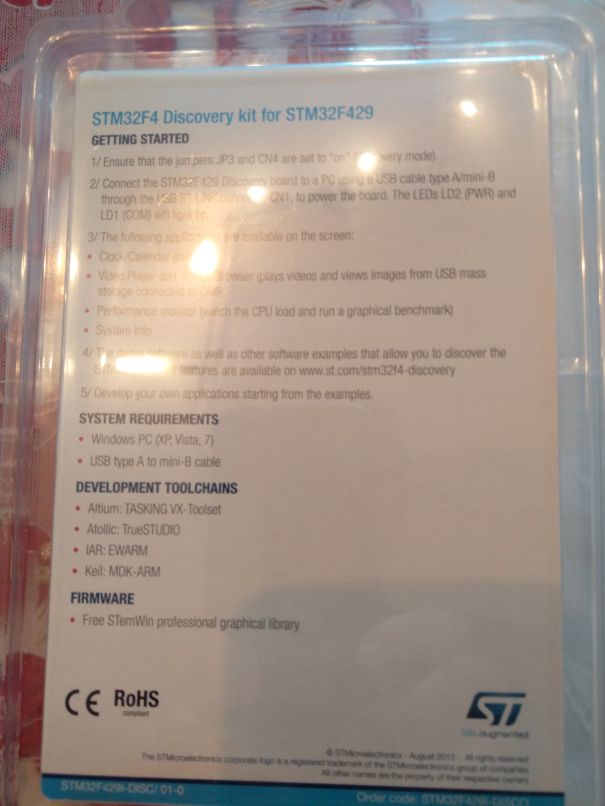
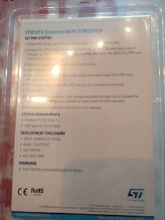
Verpackung eines STM32F4 Discovery Kits
STM32F4 Discovery kit for STM32F429 GETTING STARTED 1/ Ensure that the jumpers JP3 and CN4 are set to "on" for discovery mode. 2/ Connect the STM32F429 Discovery board to a PC using a USB cable type A/mini-B
in „[V] STM EVAL Board - STM32F429IDISCOVERY / 15,-€ incl.“ · Markt · · Fotos
-
PDF
Bauteile.pdf
16 579-MCP125233X50I/MS 1,86 € MCP41100-E/SN Digitalpoti 100kohm 2 579-MCP41100-E/SN 2,08 € B240-13F Diode 40V 2A SMA 2 621-B240-F 0,47 € 25LC640-I/SN EEPROM 64 kbit 9 579-25LC640-I/SN 0,97 € AT24C1024 EEPROM 1MBit 8 A25L80P Flash 8MB 20 L3G4200D Gyro 1 511-L3G4200D B32921C3103M Kondensator 10nF 305VAC
in „[V] diverse Bauteile“ · Markt ·