. LED brightness is easily controlled with a single pot. The LM3915 is very versatile. The outputs can drive LCDs, vacuum fluorescents and incandescent bulbs as well as LEDs of any color. Multiple devices can be cascaded for a dot or bar mode display with a range of 60 or 90 dB. LM3915s can also be cascaded
that in the 2-phase the current is flowing on one winding while the other winding is turned off/idle at every commutation. Due to the square wave BEMF pattern, the motor commutation sequence on the single or two-phase BLDC motor can be implemented the instant the BEMF changes its state or a rising/falling
Microcontroller Component Details Supported boards ST STM32H747XI Processor Dual Core Arm® Cortex®-M7 core at up to All 480 MHz with double-precision FPU and 16K data + 16K instruction L1 cache Arm® 32-bit Cortex®-M4 core at up to 240 MHz with FPU, Adaptive real-time accelerator (ART AcceleratorTM) Flash Memory
isolation barrier: channel reinforced digital isolators with an integrated – >100-Year projected lifetime at 1 kV RMS high-efficiency power converter. The integrated DC- working voltage DC converter provides up to 650 mW of isolated power at high efficiency and can be configured – Up to 5000 V RMS isolation
enters PWR_DN mode and the program registers are reset to default PL_RST_PD≥ 400 ns value. The devices can be placed into power-down (PWR_DN) mode by pulling the RST/PD pin to a logic low state for at least 400 ns. The RST/PD pin is asynchronous to the clock; thus, RST/PD can be triggered at any time regardless
input signal increases, a comparator will switch on another indicating LED. This resistor divider can be connected between any 2 voltages, providing that they are 1.5V below V+ and no less than V−. If an expanded scale meter display is desired, the total divider voltage can be as little as 200mV. Expanded-scale meter displays are more accurate and the segments light uniformly only if bar mode is used. At 50mV or more per step, dot mode is usable. [/code]
D550 CAN BUS address is defined at 144 (or 0x90 in hexadecimal value). Figure 11 - EasyReg Advance CAN address configuration Note: D550 address change will be considered at product start-up only. For this example
(1 mA) ≤|0% 40 ±2 °C, 90 to 95% r. H. for 56 days Rins≥1 MΩ withoutload/with10%ofthemaximum continuous DC operating voltage V DC . Then stored at room temperature and normal humidity for 1 to 2 h. Thereafter, the change of V
repre-sents Device Capacitor Value Change Factor the maximum practical continuous output power level that can be obtained under the following assumed conditions: 1μF 1.035 LNK613 10 μF 1.055 1. The minimum DC input voltage is 90 V or higher at 85 VAC input. 1μF 1.045 The value of the input capacitance should
の40kHzに於ける 音圧の変化:±3dB以内 The variation of the sound pressure level at 40.0kHz is within ±3dB compared with initial figures at 25℃ in 24 hours after following test conditions : 温度 Temperature : 65 ±2℃ 湿度 Humidity : 90% ~ 95% 90 to 95% R.H. 時間 Time : 1000時間 1000 hours 6-
の40kHzに於ける 感度の変化:±3dB以内 The variation of the sensitivity at 40.0kHz is within ±3dB compared with initial figures at 25℃ in 24 hours after following test conditions : 温度 Temperature : 65 ±2℃ 湿度 Humidity : 90% ~ 95% 90 to 95% R.H. 時間 Time : 1000時間 1000 hours 6-
FREQ or PERIOD . The start MODIFY, the RANGE ▲ / keys and the phase is fixed at 0° if thPHASE key is inactive. CURSOR ◄ key after pressing the corresponding The start phase can be varied between −90° and key STOP , START , MODE or PERIOD . It is addi- +90° using the START PHASE
Built-In Controllers.’) • Allowing for being connected at general-purpose CMOS signal level, the • Built-in an LCD panel which operates unit can be easily interfaced to a from a single 5 V power supply and in a wide range of temperature, offering microcomputer
peripherals in the always-on domain. As an example, the ULP sense subsystem consumes only 14 µA running at 2 MHz while performing a 100 kbit/s I²C transaction. There are seven low-power modes, enabling sub-µA power consumption in the deepest sleep modes. For example, the MCX L can achieve 650 nA with button
operating system instead of an application platform. Considering that there’s a launcher and apps, and you can develop applications with an SDK, and you can run apps from an SD card … and the whole thing runs on FreeRTOS (RTOS stands for Real-Time Operating System), I decided it is appropriate to call it an
HARMONIC IN S ( A = 2 –60 R L= 500Ω N V ) A V 1 ) T–50 d–70 ( AV= 1 R K T T A O D–60 S–80 S 50 I O E N R–90 V AV= –1 M–70 C O A 2ND HARMONIC –100 H–80 –110 –90 –120 0 100k 200k 400k 1M 2M 4M 10M 100k 1M 10M 100M 10p 100p 1000p 0.01µ 0.1µ 1µ FREQUENCY (Hz) FREQUENCY (Hz) CAPACITIVE LOAD (F) 135859 G28 135859
www.fairchildsemi.com NM93C46 Rev. E M N I M C 9 Functional Description The status of the internal programming cycle can be polled at any R C time by bringing the CS signal high again, aftCS tterval. When O 4 A typical Microwire cycle starts by first selecting the device CS signal is high, the DO pin indicates the READY
DEFAULT_bedKp 10.00 #define DEFAULT_bedKi .023 #define DEFAULT_bedKd 305.4 // FIND YOUR OWN: "M303 E-1 C8 S90" to run autotune on the bed at 90 degreesC for 8 cycles. #endif // PIDTEMPBED //=========================================================================== //==================== PID > Chamber Temperature
may cause permanent damage to the device. These are stress ratings only and operation of the device at these or at any other conditions above those given in the Characteristics sections of this specification is not implied. Exposure to limiting values for extended periods may affect device reliability
the T-bit as source and destination for the operated bit. A bit from a register in the Register File can be cop- ied into T by the BST instruction, and a bit in T can be copied into a bit in a register in the Register File by the BLD instruction. 16 AT90S2313 0839I–AVR–06/02 AT90S2313 Bit 5 – H: Half-carry
Ihrem Controller passenden Pin-Num- mern zu ermitteln. HINWEISE, TIPPS! Einige AVR-Controller (z.B. AT90CAN32/64/128, ATMega64/128) haben spezielle Programmierpins PDI, PDO. Bitte benutzen Sie diese Leitungen anstatt MISO/MOSI (siehe Datenblatt). ERFOS-AVR-ISP unterstützt die adaptive SPI-Bitratenanpassung
should match the PWM duty cycle within ±10%. If no control signal is present the fan shall operate at maximum RPM. See Figure 3. Figure 3 Fan Speed Response to PWM Control Input Signal Speed vs. PWM Duty cycle %of full speed Max. 100 PWM 90 Max. 80 RPM 70 60 Min. PWM 50 40 30 Minimum specified RPM must
offsets. Dimensions given are measured at the widest point (parting line). 2. Exact body and lead configuration at vendor’s option within limits shown. 3. Height does not include mold gate flash. 4. Where no tolerance is specified, dimension
of the IC’s potential performance. 3. The formulas given are for the typical characteristics only at 25▯C. 4. To calculate total supply current at loads other than 50 pF: T(CL) = T (50 pF) + LC – 50) Vfk where: I is in ▯A (per package), C in pF, V = (– V ) in volts, f in kHz is input frequency, and
transformer. Then connect the unit to an adjustable interrupting transformer for a functional check. You can easily and safely check the unit for a short circuit by slowly adjusting the mains voltage upwards and observing the current consumption. At the same time you can find out which functions of the unit
Miniature Package SOT-23-6. z Protection IC for One-Cell Lithium-Ion / z Ultra-Low Quiescent Current at 3£g A Lithium-Polymer Battery Pack (Vcc=3.9V). z Ultra-Low Power-Down Current at 0.1£g A (Vcc=2.0V). z Precision Overcharge Protection Voltage 4.25V ± 50mV z Load Detection Function during Overcharge
but which have a different B.O.M. format number. AARA Automatic Aspect Ratio Adaptation: By looking at the third digit of the serial number, one can algorithm that adapts aspect ratio to identify which B.O.M. is used for the TV set he is working with. remove horizontal black bars; keeps If the third digit
and/or differential measurement techniques. Capacitive coupling offers a high level of integration at a relatively low cost. A potential disadvantage is that unwanted AC common-mode voltages can flow across the barrier; however, this can be easilymanaged because capacitance values arepicofarads or less
current stress can be reduced and the efficiency can be improved. References 1. “AN-1157 Positive to Negative Buck-Boost Converter SW1 10 V/div) Using LM267X SIMPLE SWITCHER ® Regulators,” Application Report, Texas Instruments
WiperLock bits, the Write Protect bit, and if an EEPROM write cycle is active. The STATUS register can be accessed via the READ commands. Register 4-1 describes each STATUS register bit. The STATUS register is placed at Address 05h. REGISTER 4-1: STATUS REGISTER (ADDRESS = 0x05) R-1 R-1 R-1 R-1 R-1 R
Oldies.... C stammt aus den 70ern, C++ aus den 80ern, AVR und der dazugehörige Assembler aus den 90ern, Rust aus den 2000ern. Also eigentlich hätte man AVRs direkt in C und C++ programmieren können, und jetzt sogar auch in Rust. ARM hat in den 80ern angefangen, und lässt sich natürlich auch super in
they figured that somebody was going to buy this processor to use for a company, and their company can pay a few thousand dollars in time-sharing charges to use an assembler that was available in time-share. I didn’t have any money like that, so a friend taught me that you just sort of look at each instruction
main left and right channel audio output data. See Note 3. AV2CTRL0 O LRCK, audio data word clock at the audio sample rate (Fs). Maximum currently supported frequency is 192kHz. AV2CTRL1 O MCLK, audio master clock at 256Fs. This can be used to clock an external D/A converter or DSP. AV2CLK O SCLK, audio
multiplexer and the converter can be developed separately from one another and optimized for e▯ciency and/or costs. Fifth, a power multiplexer can be implemented more easily if the switching process can be done at low frequency (10Hz
https://www.raspberrypi.com/news/raspberry-pi-500-and-raspberry-pi-monitor-on-sale-now/ Der um 90 US-Dollar erhältliche und unter der URL https://www.raspberrypi.com/products/raspberry-pi-500/ im Detail beschriebene Raspberry Pi 500 ist dabei eine „neue“ Variante des Tastatur-Computers, die auf der
engineers tweaked SDRAM timings and other memory settings on the Pi, resulting in a 10-20% speed boost at the default 2.4 GHz clock. I of course had to test overclocking, which got me a 32% speedup at 3.2 GHz! Changes may roll out in a firmware update for all Pi 5 and Pi 4 users soon. [/c] Mittelfristig
the I C interface. Transition and Better Switching Noise Immunity at The key controller debounces inputs and maintains a the SCL and SDA Inputs: Typical V hysat 1.8 V is 10 byte FIFO of key-press and release events which 0.18 V can store up to 10 keys with overflow wrap
SUMMARY ® • TrenchFET Power MOSFET VDS (V) R DS(on)) I (A)a, e Qg(Typ) 100 % R and UIS Tested D g 0.007 at GS = 10 V 50 Compliant to RoHS Directive 2011/65/EU 30 25 nC 0.009 at GS = 4.5 V 40 APPLICATIONS D OR-ing Server TO-252 DC/DC G G D S S Top View N-Channel MOSFET ABSOLUTE MAXIMUM RATINGS (T = 25 °C,
are subject to change At 9 kHz: 35 dB without notice. At 10 kHz: 40 dB 5) You can change theAM tuning scale to 9 kHz or 10 kHz. After tuning in anyAM station, turn off the receiver. Hold down PRESET TUNING + and press ?/1 .
addressed has to generate an Acknowledge after receiving each byte; otherwise, the SDA Line will remain at the High Level during the ninth (9th) Clock Pulse. In this case, the master transmitter can generate the STOP Information in order to abort the transfer. TRANSMISSION WITHOUT ACKNOWLEDGE If you want
Light is on to indicate panel V & I controls are de-activated. b. There are 3 preset output P1/ P2/ P3 at the Recall Selection Switch (10) c. The preset values are factory set as following table. d. End user can set his own output rating, please refer to paragraph 6.3 Recall No. Output Voltage Output Current
TEST METHOD PERFORMANCE REQUIREMENTS Power Rating (Rated AmbientTemperature) Full Power dissipation at 70°C and linearly derated to zero at 350°C (Refer Derating Curve above) ResistanceTolerances Available ±10% (K); ±5% (J); ±3% (H); ±2% (G); ±1% (F) Temperature Range -55°C to +350°C with suitable derating
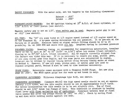
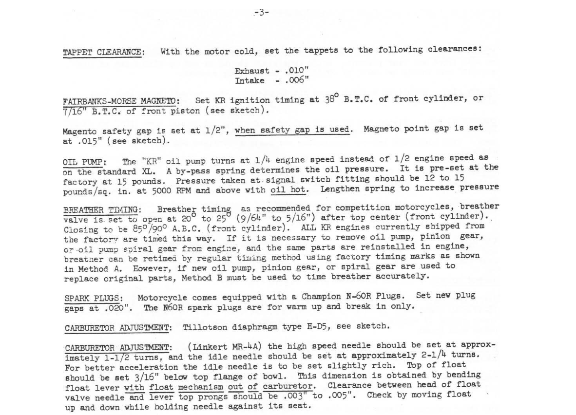
following clearances:
Exhaust -.010"
Intake .006"
FAIRBANKS-MORSE MAGNETO: Set KR ignition timing at 38° B.T.C. of front cylinder, or 7/16" B.T.C. of front piston (see sketch).
Magneto point gap is set at 1/2", when safety gap is used. Magneto point gap is set at .015" (see sketch).
OIL PUMP: The "KR" oil pump turns at 1/4 engine speed instead of 1/2 engine speed as on the standard XL. A by-pass spring determines the oil pressure. It is pre-set at the factory at 15 pounds. Pressure taken at signal switch fitting should
current operated device. Applied voltage must be sufficient to develop the minimum current requirement at all operating condition. Coil requirements are specified at stripe input terminals. Coil Resistance 18,0 Ω + 10 % (at +20°C ambient) Temperature resistance coefficient 0,004 deg -1 Equivalent circuit
Evtl. mit Projekt fuer einen der Bausaetze anfangen: https://github.com/ruthsarian/at89c2051_clock Ist zwar noch fuer at89c2051 aber in C, sollte also uebertragbar sein.
Also es ist fast wie verflucht. Hab nochmal eine negative Versorgung mit MC34063 (-23V bei 5V/90mA) aufgebaut. Läuft gut, stabile -23V. Ich habe alle Vccs und GNDs miteinander verbunden, trotzdem leuchtet kein einziges Segment. Kein Witz.🙂 Bei „getrennter Versorgung“ von LM9022/Atmega(je
Brennstoffkosten sind laufzeitproportional. Und wenn ich eine Dunkelflaute oder ähnliches habe und 90% der Erneuerbaren ausfallen, muss ich die 90% Netzleistung an konventionellen Erzeugern vorhalten! Auch wenn die im Jahresmittel kaum laufen! Na, klingelt's? Du kannst natürlich auch die wenigen Wochen
GESAMTBETRACHTUNG! Und wie war das doch gleich? Die Windbrache kämpft mit Insolvenzen. How come? "You can ignore reality. But you can't ignore the consequences of ignoring reality." Die Ossis haben die Geschichte schon mal durch. Mal sehen wie es diesmal endet. EOD
_ PFC T ON _ MAX]= 2 VACMin _PFC ON width is short at the high AC voltage. Therefore, the ON width is decided with the minimum AC voltage. It recommends RT setting such as the maximum ON width is just covered at the minimum AC voltage. ON width is small

 Bild
Bild
 Bild
Bild