-
Datei
main.c
clocks für eine Wandlung: Dauer ca. 26µs * Autotrigger mit 8MHz/256 (Timer overflow) = 31.25kHz --> 32µs */ #include <avr/io.h> #include <avr/interrupt.h> #include <avr/pgmspace.h> #include <util/delay.h> volatile uint8_t adcvalue; const uint16_t square_number[] PROGMEM = { 16384,16129,15876,15625,15376,15129,14884,14641,14400,14161,13924,13689,13456,13225,12996,12769
in „ATTiny25: unklare Interaktion PROGMEM <-> ADC“ · Mikrocontroller und Digitale Elektronik ·
-
Datei
profibus.c
WCFG) in den Zustand "Data Exchange" (DXCHG) // IO Konfiguration: // Kompaktes Format fuer max. 16/32 Byte IO // Spezielles Format fuer max. 64/132 Byte IO // Je nach PDU Datengroesse mehrere Bytes auswerten // LE/LEr - (DA+SA+FC+DSAP+SSAP) = Anzahl Config Bytes // FIXIT: module 1 Byte input + 16 Byte
-
Datei
dude5.4arduino_avr911.txt
not exist or is not a regular file, skipping Using Port : /dev/cu.SLAB_USBtoUART Using Programmer : avr911 Overriding Baud Rate : 19200 AVR Part : ATMEGA8 Chip Erase delay : 10000 us PAGEL : PD7 BS2 : PC2 RESET disposition : dedicated RETRY pulse : SCK serial program mode : yes parallel program mode :
in „avrdude - Probleme unter Mac OS X 10.7 (Lion)“ · Mikrocontroller und Digitale Elektronik ·
-
Datei
wiring.c
+; #else if ((TIFR & _BV(TOV0)) && (t < 255)) m++; #endif SREG = oldSREG; return ((m << 8) + t) * (64 / clockCyclesPerMicrosecond()); } void delay(unsigned long ms) { uint32_t start = micros(); while (ms > 0) { yield(); while ( ms > 0 && (micros() - start) >= 1000) { ms--; start += 1000; } } } /* Delay
in „Sekunden,Minuten zählen mit der Funktion Millis()“ · Mikrocontroller und Digitale Elektronik ·
-
PDF
ImplementierungEinerFiniteStateMachine.pdf
von ToDoLink heruntergeladen werden kann. Das Beispiel ist so ausgeführt, dass es im Simulator des AVR-Studio 4 nachvollzogen werden kann. Als C++ Compiler wird avr-g++ verwendet, welcher unter anderem in WinAVR vorhanden ist. Die Idee der Tabellenvariante kann natürlich auch in C umgesetzt werden. Dazu
in „Artikel über Finite State Machines“ · Mikrocontroller und Digitale Elektronik ·
-
Datei
main.c
//Eingänge uint8_t ees = 0, ehs = 0, egg = 0, egl = 0, egr = 0, egm = 0, egw = 0; uint8_t eesold = 64, ehsold = 32, eggold = 128, eglold = 2, egrold = 64, egmold = 16, egwold = 128; uint16_t eescounter = 0, ehscounter = 0, eggcounter = 0, eglcounter = 0, egrcounter = 0, egmcounter = 0, egwcounter = 0
in „Flash Speicher sparen“ · Mikrocontroller und Digitale Elektronik ·
-
Datei
dw_programming_dragon.txt
. [88] . [0f] y [79] . [c0] avrdude: jtagmkII_recv(): avrdude: jtagmkII_recv(): Got message seqno 32 (command_sequence == 32) avrdude: Recv: . [80] Raw message: 0x80 OK #avrdude: jtagmkII_paged_write(.., flash, 64, 64) avrdude: jtagmkII_paged_write(): block_size at addr 1408 is 64 avrdude: jtagmkII_paged_write
in „avrdude fuses aus debugwire schreiben“ · Mikrocontroller und Digitale Elektronik ·
-
PDF
A300_DS_DIAMEX-AVR_REF1.pdf
Installation: - Windows eigener Treiber. Einbindung durch einfache *inf Datei bis von XP bis WIN7 (32 und 64bit Version) Unterstützung folgender Chips: Classic AT90S1200, AT90S2313, AT90S2333, AT90S2343, AT90S4414, AT90S4433, AT90S4434, AT90S8515, AT90S8535 Tiny ATtiny12, ATtiny13, ATtiny15, ATtiny2313
in „Universeller RC5-Fernbedienungsempfänger“ · Mikrocontroller und Digitale Elektronik ·
-
Datei
megaAVR0_Usart.h
****************/ /* Basiert auf dem Grundkonzept von Peters Fleury Lib. */ #pragma once #include <avr/io.h> #include <avr/interrupt.h> #include <avr/pgmspace.h> #include "megaAVR0_UsartRegister.h" //* constants *// // Size of the circular rx/tx buffer, must be power of 2. constexpr uint8_t BUFFERSIZE
in „AVR C Programmierung unter Linux“ · Mikrocontroller und Digitale Elektronik ·
-
Datei
LED-Controller.c
defined by the uint8_t byte uint8_t led_green[4][8][8]; uint8_t led_blue[4][8][8]; */ uint8_t red0[64], red1[64], red2[64], red3[64]; uint8_t blue0[64], blue1[64], blue2[64], blue3[64]; uint8_t green0[64], green1[64], green2[64], green3[64]; //static void fillDriverICs(uint8_t currentZLayer); static
in „Atmega SPI Geschwindigkeit (Arduino schneller als C?)“ · Mikrocontroller und Digitale Elektronik ·
-
Datei
main.c
#include <stdlib.h> #include <avr/io.h> #include <avr/interrupt.h> #include <avr/sleep.h> #include <avr/pgmspace.h> #include "main.h" #include "lcd.h" #include <util/delay.h> volatile uint8_t spi_index; volatile taste_t taste, taste_n
in „AVR als SPI Slave-Peripherie“ · Mikrocontroller und Digitale Elektronik ·
-
Datei
ausgabe.txt
2007-2014 Joerg Wunsch System wide configuration file is "F:\ATMEL_Daten\AVRDUDE\avrdude-6.2-mingw32\avrdude.conf" Using Port : usb Using Programmer : ehajo-isp Setting bit clk period : 50.0 avrdude: usbdev_open(): Found USBtinyISP, bus:device: bus-0:\\.\libusb0-0001--0x16d0-0x0ba5 AVR Part : ATmega8
in „Keine Verbindung zwischen uISP-Stick und Atmega-8A“ · Mikrocontroller und Digitale Elektronik ·
-
Datei
avraes.asm
$92,$9d,$38,$f5,$bc,$b6,$da,$21,$10,$ff,$f3,$d2 .db $cd,$0c,$13,$ec,$5f,$97,$44,$17,$c4,$a7,$7e,$3d,$64,$5d,$19,$73 .db $60,$81,$4f,$dc,$22,$2a,$90,$88,$46,$ee,$b8,$14,$de,$5e,$0b,$db .db $e0,$32,$3a,$0a,$49,$06,$24,$5c,$c2,$d3,$ac,$62,$91,$95,$e4,$79 .db $e7,$c8,$37,$6d,$8d,$d5,$4e,$a9,$6c,$56,$f4,$ea
in „Assembler mit C verknüpfen“ · Mikrocontroller und Digitale Elektronik ·
-
Datei
lcd-m50530.h
Data0-3) werden 4 weitere Steuerleitungen (Read/Write, Execute, OC1, OC2) benötigt. Damit werden am AVR 8 Pins benötigt. Anschluss: Alle 8 LCD-Signale müssen an einem Port des AVR angeschlossen werden. Gemäß folgender Tabelle müssen die 4 Datenleitungen an den niederwertigsten Bits anliegen. Die Reihenfolge
in „Initialisierung M50530 LCD Display“ · Mikrocontroller und Digitale Elektronik ·
-
 Bild
Bild
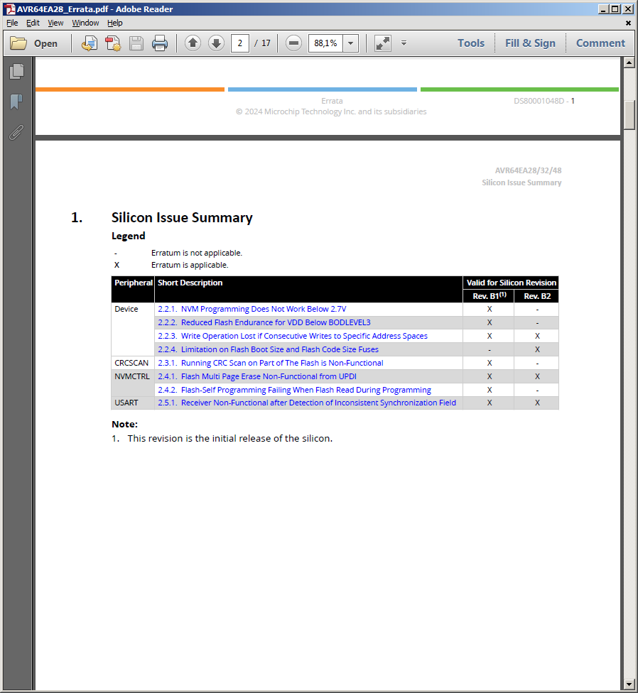
Silicon Issue Summary Errata AVR64EA28/32/48
AVR64EA28_Errata.pdf - Adobe Reader Silicon Issue Summary Legend - Erratum is not applicable. X Erratum is applicable. Peripheral Short Description Valid for Silicon Revision Device Rev. B1(1) Rev. B2 NVMCTRL 2.2.1 NVM Programming Does Not Work Below 2.7V X - 2.2.2 Reduced Flash Endurance for VDD Below BODLEVEL3 X - 2.2.3 Write Operation Lost if Consecutive Writes to Specific Address Spaces X X 2.2.4 Limitation on Flash Boot Size and Flash Code Size Fuses X X CRCSCAN 2.3.1 Running CRC Scan on Part of the Flash is Non-Functional X X NVMCTRL 2.4.1 Flash Multi Page Erase Non-Functional from UPDI X X
in „AVR64EA28: PIT-Interrupt“ · Mikrocontroller und Digitale Elektronik · · Screenshots
-
 Bild
Bild
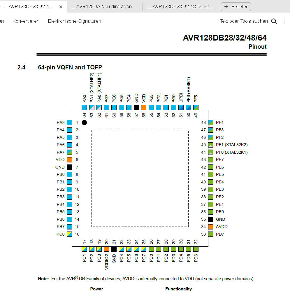
Pinbelegung AVR128DB28/32/48/64 VQFN und TQFP
AVR128DB28/32/48/64 Pinout 2.4 64-pin VQFN and TQFP PA2, PA1 (XTALHF), PA0 (XTALHF), PG7, PG6, PG4, VDD, PG3, PG2, PG1, UPD, PF6 (RESET), PF5, PF4, PF3, PF2, PF1, PF0 (XTAL32K1), PE7, PE6, PE5, PE4, PE3
in „AVR128DA64 TCA1 funktioniert nicht mit alternativen Output?“ · Mikrocontroller und Digitale Elektronik · · Screenshots
-
Datei
partlist.txt
100n C0805 rcl (21.59 13.97) MR270 C2 10µ SMC_C rcl (24.13 21.59) R180 C3 100n C0805 rcl (38.1 20.32) MR270 C4 100n C0805 rcl (40.64 20.32) MR270 C5 E5-10,5 rcl (59.055 43.18) R180 C6 100n C0805 rcl (35.56 30.48) MR270 C9 10n C0805 rcl (21.59 30.48) MR180 C10 10µ SMC_C rcl (49.53 63.5) R180 C11 4,7µ
in „CP/M auf ATmega88“ · Mikrocontroller und Digitale Elektronik ·
-
Datei
stepper.c
Ausgabestring[30]; uint16_t Stepper_max = 4300; //Eigentlich 4276 - aber geht sowieso nur bis Anschlag uint32_t Beschleunigung_Schritte; uint32_t Bremsung_Schritte; float Schritt_Faktor; float Beschleunigung_Zeit; float Bremsung_Zeit; uint64_t Frequenz; float Beschleunigung_Multiplikator; float Bremsung_Multiplikator
in „UV-Laserdrucker“ · Platinen ·
-
Datei
Compiling.txt
arduino_cache_464788\core\core_4cfe92664363663346618e8ef6c17158.a Linking everything together... "C:\\avrToolchain\\avr-gcc-13.2.0_mingw32_binutils2.41_avrLibc2.1GitHub_P02/bin/avr-gcc" -Wall -Wextra -Os -g -flto -fuse-linker-plugin -mrelax -Wl,--gc-sections,--section-start=.text=0x200,--section-start=.
in „BFD DWARF Error - avr-gcc 13.2 & binutils 2.41“ · Mikrocontroller und Digitale Elektronik ·
-
PDF
AVR-ASM-Tutorial_16_05_08_v2.pdf
• DCF77-Funkwecker mitAVR • Fahrradcomputer • Einfacher und billiger Webserver mitAtMega32 • AVR RFM12 0.6 Tutorials • AVR-Tutorial • AVR-GCC-Tutorial • http://www.avr-asm-tutorial.net - 9 - 0.7 Tipps & Hinweise • AVR Typen
in „AVR-ASM-Tutorial: PDF 16.5.08“ · www.mikrocontroller.net ·
-
Datei
wiring.c
&& defined(WGM01) sbi(TCCR0A, WGM01); sbi(TCCR0A, WGM00); #endif // set timer 0 prescale factor to 64 #if defined(__AVR_ATmega128__) // CPU specific: different values for the ATmega128 sbi(TCCR0, CS02); #elif defined(TCCR0) && defined(CS01) && defined(CS00) // this combination is for the standard atmega8
in „IRMP - Infrared Multi Protocol Decoder“ · Projekte & Code ·
-
Datei
Code.txt
25, 25, 25, 25, 26, 26, 26, 26, 27, 27, 27, 28, 28, 28, 28, 29, 29, 29, 30, 30, 30, 30, 31, 31, 31, 32, 32, 32, 33, 33, 33, 34, 34, 34, 35, 35, 35, 36, 36, 36, 37, 37, 38, 38, 38, 39, 39, 39, 40, 40, 41, 41, 41, 42, 42, 43, 43, 44, 44, 44, 45, 45, 46, 46, 47, 47, 48, 48, 49, 49, 50, 50, 51, 51, 52, 52
in „RGB Led mit PWM und 120Grad vesatz“ · Mikrocontroller und Digitale Elektronik ·
-
Datei
rf22.c
120dB rf22_write(0x30, 0x8c); // data access: RX/TX packet handling, enable crc: CCIT rf22_write(0x32, 0xcf); // header check enable rf22_write(0x33, 0x46); // 2 word synchronisation rf22_write(0x34, 0x10); // preamble length: 16 nibbles, = 64bits rf22_write(0x35, 0x30); // preamble detection control
in „RFM22B Beispiel Projekt gesucht.“ · Mikrocontroller und Digitale Elektronik ·
-
Datei
avrcpm-log.txt
H>a:stat dsk: A: Drive Characteristics 1944: 128 Byte Record Capacity 243: Kilobyte Drive Capacity 64: 32 Byte Directory Entries 64: Checked Directory Entries 128: Records/ Extent 8: Records/ Block 26: Sectors/ Track 2: Reserved Tracks B: Drive Characteristics 65536: 128 Byte Record Capacity 8192: Kilobyte
in „CP/M auf ATmega88“ · Mikrocontroller und Digitale Elektronik ·
-
Datei
main_bytebybyte.c
PRESCALE_16_MASK (( 0 << CS13 ) | ( 1 << CS12 ) | ( 0 << CS11) | ( 1 << CS10)) #define TIMER1_PRESCALE_32_MASK (( 0 << CS13 ) | ( 1 << CS12 ) | ( 1 << CS11) | ( 0 << CS10)) #define TIMER1_PRESCALE_64_MASK (( 0 << CS13 ) | ( 1 << CS12 ) | ( 1 << CS11) | ( 1 << CS10)) #define TIMER1_PRESCALE_128_MASK (( 1
in „ATtinyX5 und SPI Daisy-Chain“ · Mikrocontroller und Digitale Elektronik ·
-
Datei
123.c
#include <inttypes.h> #include <avr/io.h> #include <util/delay.h> #include <avr/pgmspace.h> #define F_CPU 4000000 // global variables uint16_t pwmtable_10[64] PROGMEM = {0, 1, 1, 2, 2, 2, 2, 2, 3, 3, 3, 4, 4, 5, 5, 6, 6, 7, 8, 9, 10, 11, 12, 13, 15, 17, 19, 21, 23, 26, 29, 32, 36, 40, 44, 49, 55, 61, 68, 76, 85, 94, 105, 117, 131, 146, 162, 181, 202, 225, 250, 279, 311, 346, 386, 430, 479, 534, 595, 663, 739, 824, 918, 1023}; void pwm_10_64(int16_t tmp) { TCCR0A = (1<<COM0A1
in „LED Fading und Uhr beides benötigt Timer1“ · Mikrocontroller und Digitale Elektronik ·
-
Datei
rf22.c
Funkmodule ------------------------------------------------------------------------------*/ #include <avr/io.h> #include <avr/interrupt.h> #include <avr/pgmspace.h> #include "rf22.h" #include "usart.h" //####################################################################################################
-
Datei
rf22.c
Funkmodule ------------------------------------------------------------------------------*/ #include <avr/io.h> #include <avr/interrupt.h> #include <avr/pgmspace.h> #include "rf22.h" #include "usart.h" //####################################################################################################
in „rfm22b Empfänger läuft nicht“ · Mikrocontroller und Digitale Elektronik ·
-
Datei
fft232slow.asm
elm-chan.org/ ; ;-----------------------------------------------------------------------------; ; .include "m32def.inc" .include "avr.inc" .include "akiglcd.inc" .equ Sync = 3 ;Port D bit definitions .equ FFT_N = 128 ;Number of samples .equ LCD_H = 16 ;/ .def ClkDiv = r12 ;ADC SampleClock Divider for T0 .def _
in „Schnelle FFT in Assembler“ · Digitale Signalverarbeitung / DSP / Machine Learning ·
-
PDF
KOMMPROT.pdf
Bytes vertauscht) D 1 Byte 0x30 bzw. 0x31 Festlegen des verwendeten EEPROM-Typs 0: Gesamtspeicher 64kByte 1: Gesamtspeicher 128kByte Blockgröße des Speichers: 64 Byte D 0x00 PC-V sendet EEPROM-Typ E 2 Byte hex Steigung E 2 Byte 0x0000 PC-V sendet aktuelle Steigung F 2 Byte hex Nullstelle F 2 Byte 0x0000
in „RS-232 Daten auslesen und verarbeiten“ · PC Hard- und Software ·
-
Datei
stepper.c
Ausgabestring[30]; uint16_t Stepper_max = 4300; //Eigentlich 4276 - aber geht sowieso nur bis Anschlag uint32_t Beschleunigung_Schritte; uint32_t Bremsung_Schritte; float Schritt_Faktor; float Beschleunigung_Zeit; float Bremsung_Zeit; uint64_t Frequenz; float Beschleunigung_Multiplikator; float Bremsung_Multiplikator
in „UV-Laserdrucker II“ · Platinen ·
-
Datei
main.c
*******************************************************************/ #include "define.h" #include <avr\io.h> #include <avr\interrupt.h> #include <stdint.h> #include <util\delay.h> #include <avr/pgmspace.h> #include <stdlib.h> #include <string.h> #include <avr\eeprom.h> #include <avr\sleep.h> #include
in „AD-Wandlung und Nutzung JTAG möglich?“ · Mikrocontroller und Digitale Elektronik ·
-
Datei
main.c
/* * IRLog.c * * Created on: 07.07.2011 * Author: jmm */ #include <avr/interrupt.h> #define sbi(x,b) (x |= (1 << (b))) #define cbi(x,b) (x &= ~(1 << (b))) #define BAUD 115200 #define CPUFREQ 16000000UL #define EPSILON (0.0005) #define PS 32 #if (PS == 1) #define PSOR 1
in „Mini-Helikopter“ · Mikrocontroller und Digitale Elektronik ·
-
Datei
LED-Controller.c
defined by the uint8_t byte uint8_t led_green[4][8][8]; uint8_t led_blue[4][8][8]; */ uint8_t red0[64], red1[64], red2[64], red3[64]; uint8_t blue0[64], blue1[64], blue2[64], blue3[64]; uint8_t green0[64], green1[64], green2[64], green3[64]; uint8_t leds0[192], leds1[192], leds2[192], leds3[192]; //
in „Atmega SPI Geschwindigkeit (Arduino schneller als C?)“ · Mikrocontroller und Digitale Elektronik ·
-
Datei
optiboot_atmega128.lst
TWO_STOP_BITS<<USBS0)|(1<<UCSZ01)|(1<<UCSZ00) ;config UART U8N2 AOUT UART_SRC, r23 #else /* no ATmega8_16_32 */ #if !defined(__AVR_ATmega163__) && !defined(__AVR_ATtiny87__) && !defined(__AVR_ATtiny167__) ldi r23, (TWO_STOP_BITS<<USBS0)|(1<<UCSZ00)|(1<<UCSZ01) ;config UART U8N2 1fc4a: 7e e0 ldi r23, 0x0E ;
in „Tester für Spezialversion des AVR Bootloaders optiboot gesucht!“ · Mikrocontroller und Digitale Elektronik ·
-
PDF
AVR_Roboter_Dokumentation.pdf
Technology Infrastructure, Lab Service, Lehrer Workshop Januar 2009 Fragen ? COMPANY CONFIDENTIAL 32 Shared Technology Infrastructure, Lab Service, Lehrer Workshop Januar 2009 Motoren Motor- bzw. Getriebeblock AVR-Mops System Überblick Hardware Sensoren Pulsweiten Modulation (PWM) Speicher Interfaces
in „Anfängerprobleme“ · Mikrocontroller und Digitale Elektronik ·
-
PDF
Befehlssatz.pdf
Call-Anweisung enthält, wird in den Stack gesichert (siehe auch RCALL). Dieser Befehl ist nicht in allenAVR- Mikrocontrollern verfügbar. (a) PC ← k, Bausteine mit 16 Bit PC (128k) Operation: (b) PC ← k, Bausteine mit 22 Bit PC (8M) (a) 0 ≤ k ≤ 64k, STACK ← PC+2, SP ← SP-2 Operanden: (b) 0 ≤ k ≤ 4M, STACK
in „Befehlsliste“ · Mikrocontroller und Digitale Elektronik ·
-
Datei
pwm.cc
------------------------------------------------------ #define F_CPU 3686400 // Taktfrequenz des myAVR-Boards #include <avr\io.h> // AVR Register und Konstantendefinitionen #include <util\delay.h> // Bibliothek mit Warteroutinen //----------------------------------------------------------------------
in „Analog einlesen und als PWM ausgeben“ · Mikrocontroller und Digitale Elektronik ·
-
Datei
pwm.cc
------------------------------------------------------ #define F_CPU 3686400 // Taktfrequenz des myAVR-Boards #include <avr\io.h> // AVR Register und Konstantendefinitionen #include <util\delay.h> // Bibliothek mit Warteroutinen //----------------------------------------------------------------------
in „Analog einlesen und als PWM ausgeben“ · Mikrocontroller und Digitale Elektronik ·
-
Datei
pwm.cc
------------------------------------------------------ #define F_CPU 3686400 // Taktfrequenz des myAVR-Boards #include <avr\io.h> // AVR Register und Konstantendefinitionen #include <util\delay.h> // Bibliothek mit Warteroutinen //----------------------------------------------------------------------
in „Analog einlesen und als PWM ausgeben“ · Mikrocontroller und Digitale Elektronik ·
-
Datei
pwm.cc
------------------------------------------------------ #define F_CPU 3686400 // Taktfrequenz des myAVR-Boards #include <avr\io.h> // AVR Register und Konstantendefinitionen #include <util\delay.h> // Bibliothek mit Warteroutinen //----------------------------------------------------------------------
in „Analog einlesen und als PWM ausgeben“ · Mikrocontroller und Digitale Elektronik ·
-
PDF
D550_CAN_BUS_Interface.pdf
list: Group Menu Paramet Parameter name Uni Type Bytes R/ Range er t W Customer 000 002 UN V FLOAT32 4 R From 0 to Informations 100000 Customer 000 003 VN V FLOAT32 4 R From 0 to Informations 100000 Customer 000 004 WN V FLOAT32 4 R From 0 to Informations 100000 … … … … … … … … … Gains 003 005 Current
-
PDF
DA74175765702C785FEFD64B394D9CB1.pdf
Features General ® • High-performance, Low-power AVR (AVR3 Core) Enhanced RISC Architecture – 133 Powerful Instructions (Most Executed in a Single Clock Cycle) Low-power Idle and Power-down Modes Bond Pad Locations Conforming to ISO 7816/2 ESD Protection
in „AT90SC6464C ??“ · Mikrocontroller und Digitale Elektronik ·
-
Datei
bootload.lst
10 ; ***** BOOTLOADER DECLARATIONS ****************************************** 11 #define PAGESIZE 32 31 32 #define byte3(x) ((x)>>16) 33 #define byte2(x) ((x & 0xff00)>>8) 34 #define byte1(x) (x & 0xff) 35 36 37 /* 38 Atmel's AVR assembler is case insensitive, gcc is not. 39 mangled_case.h covers the
in „Peter Danneggers Bootloader (fastboot) für AVR-GCC-Toolchain“ · Projekte & Code ·
-
Datei
main.c
//Eingänge uint8_t ees = 0, ehs = 0, egg = 0, egl = 0, egr = 0, egm = 0, egw = 0; uint8_t eesold = 64, ehsold = 32, eggold = 128, eglold = 2, egrold = 64, egmold = 16, egwold = 128; uint16_t eescounter = 0, ehscounter = 0, eggcounter = 0, eglcounter = 0, egrcounter = 0, egmcounter = 0, egwcounter = 0
in „Flash Speicher sparen“ · Mikrocontroller und Digitale Elektronik ·
-
Datei
Test3.c
#include <stdint.h> #include <avr/io.h> #include <inttypes.h> #define F_CPU 1000000 #include <util/delay.h> #include <avr/sleep.h> #include <avr/interrupt.h> #include <util/atomic.h> #define LED_TOGGLE_CYCLE 200 #define LED_TOGGLE_CYCLE_bat
in „Tasterabfrage“ · Mikrocontroller und Digitale Elektronik ·
-
Datei
Radar1.c
#define F_CPU 8000000UL #include <stdio.h> #include <avr/io.h> #include <avr/interrupt.h> //#include <avr/sleep.h> //#include <avr/pgmspace.h> //#include <avr/wdt.h> #include <util/delay.h> #include "uart.h" #include "globals.h" #include <stdlib.h> int main
in „Messung niedriger Frequenzen schlägt fehl“ · Mikrocontroller und Digitale Elektronik ·
-
Datei
rf22.c
Funkmodule ------------------------------------------------------------------------------*/ #include <avr/io.h> #include <avr/interrupt.h> #include <avr/pgmspace.h> #include "rf22.h" #include "usart.h" //####################################################################################################
in „RFM22B Interrupt Empfang“ · Mikrocontroller und Digitale Elektronik ·
-
Datei
lcd.c
configuration 0xDB, // --set vcomh 0x20, // 0x20,0.77xVcc 0x8D, 0x14, // Set DC-DC enable }; #if defined(__AVR_ATmega328P__) || defined(__AVR_ATmega168P__) || defined(__AVR_ATmega88P__) || defined(__AVR_ATmega48P__) || defined(__AVR_ATmega1284P__) #if PSC_I2C != 1 && PSC_I2C != 4 && PSC_I2C != 16 && PSC_I2C
in „RS485 von ms - immer noch Einschaltprobleme“ · Mikrocontroller und Digitale Elektronik ·
-
Datei
sirbundy.c
/* ATtiny2313 8 MHz Pollin Funk AVR Board */ #include <avr/io.h> #include <avr/interrupt.h> #define DEBUG 0 #define LED1 PD6 #define LED2 PD5 #define BUTTON1 PB1 #define LED_ON(LED) (PORTD |= (1<<LED)) //x or 1 = 1 #define LED_OFF(LED
in „Timer0 interrupt“ · Mikrocontroller und Digitale Elektronik ·