-
PDF
PH2520U.pdf
voltage; typical values values PH2520U_3 © NXP B.V. 2009. All rights reserved. Product data sheet Rev. 03 — 2 March 2009 8 of 12 NXP Semiconductors PH2520U N-channel TrenchMOS ultra low level FET 7. Package outline Plastic single-ended surface-mounted package (LFPAK); 4 leads SOT669 A 2 E A C c b2 2 E1 L b 3 1 mounting b base 4 D 1 D H L 2 1 2 3 4 X e b w M A c 1/2e A (A3) A1 C θ detail X L y C 0 2.5 5 mm scale DIMENSIONS (mm are the original dimensions) (1) D (1) (1) (1) UNIT A A1 A2 A3 b b 2 b3 b4 c c2 D max E E1 e H L L1 L2 w y θ
in „FET Empfehlung“ · Mikrocontroller und Digitale Elektronik ·
-
Datei
qv12.asm
SSml2 LDS RShr1, SShr1 LDS RShr2, SShr2 LDS RShl1, SShl1 LDS RShl2, SShl2 LDS Kopf, SKopf CLR Zaehl03 Rueck1: CP Zaehl03, RSvr1 BREQ S1aus aus1: CP Zaehl03, RSvr2 BREQ S2aus aus2: CP Zaehl03, RSvl1 BREQ S3aus aus3: CP Zaehl03, RSvl2 BREQ S4aus aus4: CP Zaehl03, RSmr1 BREQ S5aus aus5: CP Zaehl03, RSmr2 BREQ S6aus aus6: CP Zaehl03, RSml1 BREQ S7aus aus7: CP Zaehl03, RSml2 BREQ S8aus aus8: CP Zaehl03, RShr1 BREQ S9aus aus9: CP Zaehl03, RShr2 BREQ S10aus aus10: CP Zaehl03, RShl1 BREQ S11aus aus11: CP Zaehl03, RShl2 BREQ S12aus aus12
in „Servos ansteuern“ · Mikrocontroller und Digitale Elektronik ·
-
Datei
qv12.asm
SSml2 LDS RShr1, SShr1 LDS RShr2, SShr2 LDS RShl1, SShl1 LDS RShl2, SShl2 LDS Kopf, SKopf CLR Zaehl03 Rueck1: CP Zaehl03, RSvr1 BREQ S1aus aus1: CP Zaehl03, RSvr2 BREQ S2aus aus2: CP Zaehl03, RSvl1 BREQ S3aus aus3: CP Zaehl03, RSvl2 BREQ S4aus aus4: CP Zaehl03, RSmr1 BREQ S5aus aus5: CP Zaehl03, RSmr2 BREQ S6aus aus6: CP Zaehl03, RSml1 BREQ S7aus aus7: CP Zaehl03, RSml2 BREQ S8aus aus8: CP Zaehl03, RShr1 BREQ S9aus aus9: CP Zaehl03, RShr2 BREQ S10aus aus10: CP Zaehl03, RShl1 BREQ S11aus aus11: CP Zaehl03, RShl2 BREQ S12aus aus12
in „Grundsätzliches zur Ansteuerung von Servos mit AVR und ASM“ · Mikrocontroller und Digitale Elektronik ·
-
PDF
Unterlagen_Grubenwehrtelefonsystem.pdf
Stücke in Leitungskartusche FS 2052 / 6011) Spezifikation: - Kapazität C ≤ 55nF/km - Induktivität L ≤ 1,1mH/km - Widerstand R (2 adrig) ≥ 210Ω/km - Isolationsspannung Up ≥ 500V und / oder Flachbandleitung ( 2 - adrige Prickerleitung) Spezifikation: - Kapazität C ≤ 118nF/km - Induktivität L ≤ 1,1mH/
in „Induktives Abgreifen von Sprache an eine Grubenwehr Telefonleitung“ · Analoge Elektronik und Schaltungstechnik ·
-
PDF
Unterlagen_Grubenwehrtelefonsystem.pdf
Stücke in Leitungskartusche FS 2052 / 6011) Spezifikation: - Kapazität C ≤ 55nF/km - Induktivität L ≤ 1,1mH/km - Widerstand R (2 adrig) ≥ 210Ω/km - Isolationsspannung Up ≥ 500V und / oder Flachbandleitung ( 2 - adrige Prickerleitung) Spezifikation: - Kapazität C ≤ 118nF/km - Induktivität L ≤ 1,1mH/
in „Induktives Abgreifen von Sprache an eine Grubenwehr Telefonleitung“ · Analoge Elektronik und Schaltungstechnik ·
-
PDF
Technical-Information-Interfacing-with-VE-Bus-products-MK2-Protocol-3-14.pdf
Charge value 05 FF ‘W’ 30 0D 00 68 05 FF ‘W’ 85 (XX XX)[DD DD] <Checksum> Request the DC info frame 03 FF ‘F’ 00 B8 0F 20 (XX XX XX XX) 0C (XX XX) (XX XX XX) (XX XX XX) XX <Checksum> Request the LED status 02 FF ‘L’ B3 05 FF ‘L’ XX XX 00 f <Checksum> Instruct the MK2 to act as a remote panel - switch
-
PDF
SANMOTION_R_M0006890N.pdf
Q2EA05020D 4Z Q2AA07040D 48 Q1AA12200D 3C Q2AA18750L 7N Q2EA07020D 71 Q2AA07050D 49 Q1AA12300D 3D Q2AA2211KV 7R R2EA06020F DU Q2AA08050D 4A Q1AA13300D 3E Q2AA2215KV 7S RS1L03A Q2AA13050H 4F RS1L10A Q2AA13200H 4J R2AA18550H 9Y RS1N03A RS1A03A R2AA06040F D6 RS1A10A Q2AA18200H 4K RS1A30A R2AA18750H ES RS1E03A RS1M03A R2AA08040F D8 RS1M10A R2AA13180D 9U RS1B30A R2AA1811KR 9Z RS1P03A RS1B03A R2AA08075F D7 RS1B10A R2AA13200D DG RS1F03A R2AAB8100H DL R2AA18350L 9V R2AA10075F DY R2AA13050H DF R2AA13050D DC R2AA13120B
in „Servoregler/Servoverstärker Verständnislücke“ · Mikrocontroller und Digitale Elektronik ·
-
Datei
Alarm.c
: * Sfr file description for AT89C51CC03 product *****************************************************************************/ #ifndef _AT89C51CC03_H_ #define _AT89C51CC03_H_ #asm .include <at89c51cc03.def> #endasm /*----------------------
in „AT89C51CC03 Alarmanlage“ · Mikrocontroller und Digitale Elektronik ·
-
Datei
Alarm.c
: * Sfr file description for AT89C51CC03 product *****************************************************************************/ #ifndef _AT89C51CC03_H_ #define _AT89C51CC03_H_ #asm .include <at89c51cc03.def> #endasm /*----------------------
in „AT89C51CC03 Alarmanlage“ · Mikrocontroller und Digitale Elektronik ·
-
Datei
cd-loader.dump.hex.txt
5581 .r..u..t.:U.<2U. 0000320: 2100 00dd e1c1 c9c5 d5dd e53a 5581 b7ca !..........:U... 0000330: 4c03 47dd 2193 80dd 5e02 dd56 03cd 3433 L.G.!...^..V..43 0000340: 280f dd23 dd23 dd23 dd23 10eb 21ff ff18 (..#.#.#.#..!... 0000350: 1e3a 5581 3d32 5581 8787 6f26 0011 9380 .:U.=2U...o&.... 0000360: 19dd e5d1
in „Suche KL5C80A12 (Z80 Clone) Datenblatt / Register-Map“ · Mikrocontroller und Digitale Elektronik ·
-
PDF
vds_2005_web_1_.pdf
Publikation der deutschen Versicherer zur Schadenverhütung Leuchten VdS 2005 : 2014-03 (05) Leuchten VdS 2005 : 2014-03 (05) Zusammenfassung Die Publikation gibt Hinweise zur Planung, Auswahl, Errichtung sowie den Betrieb von Leuchten und Be- leuchtungsanlagen, inklusive Kleinspannungsbeleuchtungsanlagen
-
PDF
NHD-7.0-800480.pdf
– Operating IDD Ta=25°C, VDD=2.8V - 6.0 - mA Supply Current – Hibernate IDD Ta=25°C, VDD=2.8V - 0.03 - mA “H” Level Input Vih 0.7*VDD - VDD V “L” Level Input Vil VSS - 0.3*VDD V “H” Level Output Voh 0.7*VDD - VDD V “L” Level Output Vol VSS - 0.3*VDD V Optical Characteristics Item Symbol Condition Min
in „CAN und I2C Projektumsetzung“ · Mikrocontroller und Digitale Elektronik ·
-
Datei
R-S_CMU_HD-Files.txt
MOVE.LOG ./R-S_CMU_HD/INTERNAL/LOG/TOOLS/12-10-16.V16/VERM.LOG ./R-S_CMU_HD/INTERNAL/LOG/TOOLS/08-06-04.L08 ./R-S_CMU_HD/INTERNAL/LOG/TOOLS/08-06-04.L08/MOVE.LOG ./R-S_CMU_HD/INTERNAL/LOG/TOOLS/08-06-04.L08/LOAD_SU.LOG ./R-S_CMU_HD/INTERNAL/LOG/TOOLS/12-10-15.D03 ./R-S_CMU_HD/INTERNAL/LOG/TOOLS/12-10-15.
in „Option B41 bei einer CMU200 nachrüsten.“ · HF, Funk und Felder ·
-
Datei
Gal_a.c
*8+j); for (k=0; k<gal_type; k=k+4) { printf(" "); for (l=0; l<4; l++) { printf("%s",(fuse[i*gal_type*8+j+k+l]==TRUE) ? "-" : "X"); } } } printf("\n"); } for (i = 0; i < 8; i++) { k = 0; for(j=0; j<8; j++) { k <<= 1; k |= fuse[gal_type*64+FUSE_UES+i*8+j]; }
-
Datei
Eeprom2.txt
23 inc hl .data:0000175c 66 ld h,(hl) .data:0000175d 6f ld l,a .data:0000175e e9 jp (hl) .data:0000175f 2e 48 ld l,0x48 .data:00001761 57 ld d,a .data:00001762 48 ld c,b .data:00001763 37 scf .data:00001764 57 ld d,a .data:00001765 cd 02 03 call 0x0302 .data:00001768
in „Hilfe bei Z80 Opcodes“ · Mikrocontroller und Digitale Elektronik ·
-
Datei
FAT32_Know-How.txt
55 AA ..............Uª | Lookup Partition Entry 1 | | Partition Entry 1 in MBR 16 Bytes 000001BE 00 03 02 00 0B 07 E0 C0 61 00 00 00 9F C0 03 00 Byte 0 Boot Indicator: 0x00 Byte 1 Start Head: 0x03 Byte 2 Start Sector: 0x02 Byte 3 Start Cylinder: 0x00 Byte 4 Partitions Type: 0x0B || 0x0C <- Use Byte 5
in „MMC/SD Adresse“ · Mikrocontroller und Digitale Elektronik ·
-
PDF
EPR_Flamanville.pdf
des EELV. "Die politische Verantwortung ist nicht zu unterwerfen, ist es zu widerstehen." Le coût de l'EPR de Flamanville encore revu à la hausse Le Monde.fr avecAFP | 03.12.2012 à 22h03 • Mis à jour le 04.12.2012 à 19h14 Abonnez-vous à partir de 1 € Réagir Classer Imprimer Envoyer Partager facebook twitter
in „Was macht ihr mit eurem Geld?“ · Ausbildung, Studium & Beruf ·
-
PDF
TGS2620.pdf
Advisory‘TechnicalInformationonUsageofTGSSensors for Toxic and Explosive Gas Leak Detectors’). Methane 1 l Air 0 0 1000 2000 3000 4000 5000 6000 Gas concentration (ppm) Fig. 5 - Sensitivity to various gRL)s (V Revised 03/05 4 TECHNICAL INFORMATION FOR TGS2620 2-2 Temperature and humidity dependency 10 RH%
in „TGS2620 Raumluftsensor -> Wie RL wählen“ · Mikrocontroller und Digitale Elektronik ·
-
Datei
mcp_flipdot_hc05.ino
0x07, 0x05, 0x01, 0x01, 0x01}, // 7 {0x07, 0x05, 0x07, 0x05, 0x07}, // 8 {0x07, 0x05, 0x07, 0x01, 0x03}, // 9 {0x00, 0x07, 0x00, 0x07, 0x00}, // 0xA = {0x00, 0x00, 0x00, 0x00, 0x00}, // 0xB BLANK {0xFF, 0xFF, 0xFF, 0xFF, 0xFF}, // 0xC ALL {0x01, 0x01, 0x01, 0x01, 0x01}, // 0xD L (13) {0x03, 0x03, 0x03
in „Flipdot Display Projekt (Hilfe Logik Erbeten)“ · Mikrocontroller und Digitale Elektronik ·
-
 Bild
Inhaltsverzeichnis einer Bauteilliste
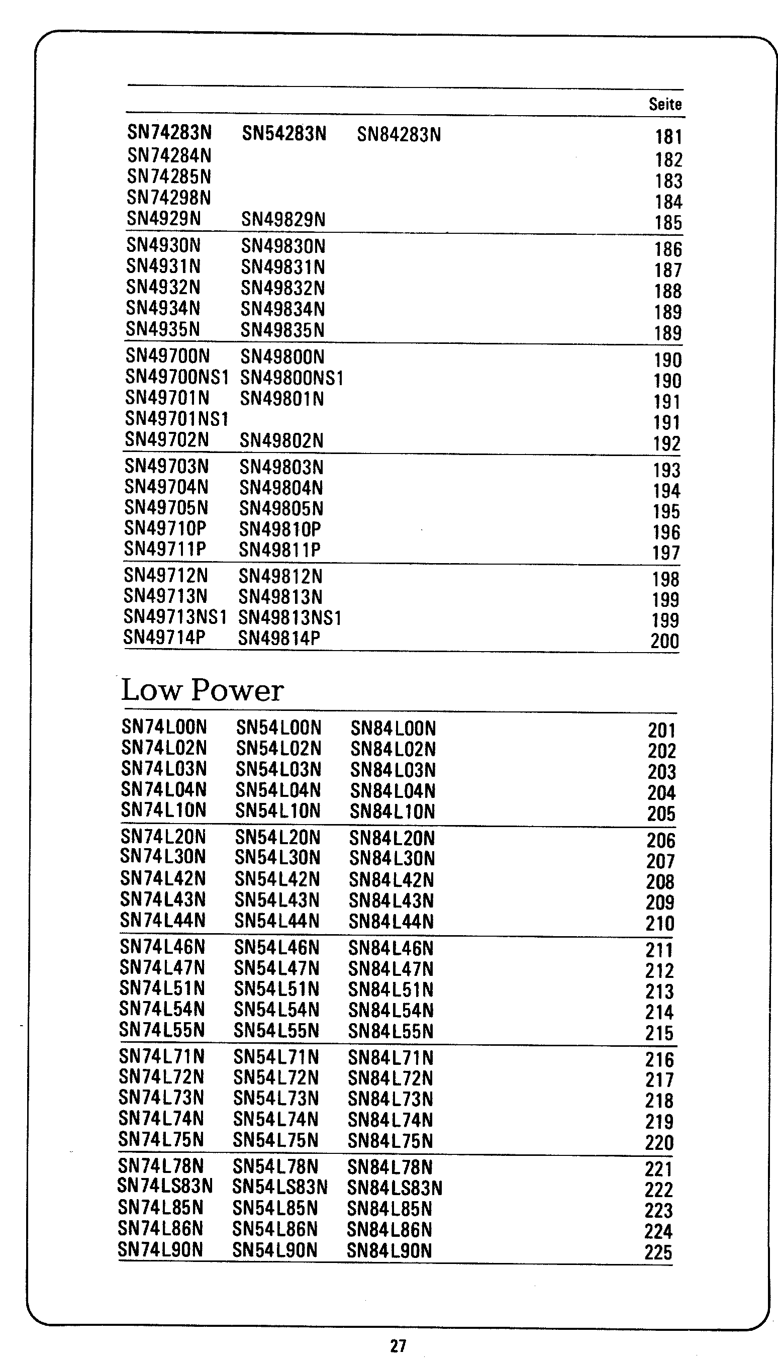
SN49712N SN49812N 198 SN49713N SN49813N 199 SN49713NS1 SN49813NS1 199 SN49714P SN49814P 200 Low Power SN74L00N SN54L00N SN84L00N 201 SN74L02N SN54L02N SN84L02N 202 SN74L03N SN54L03N SN84L03N 203 SN74L04N SN54L04N SN84L04N 204 SN74L1
in „[S] Datenblatt zum SN49LS711P“ · Markt · · Screenshots

-
 Bild
Inhaltsverzeichnis einer Bauteilliste
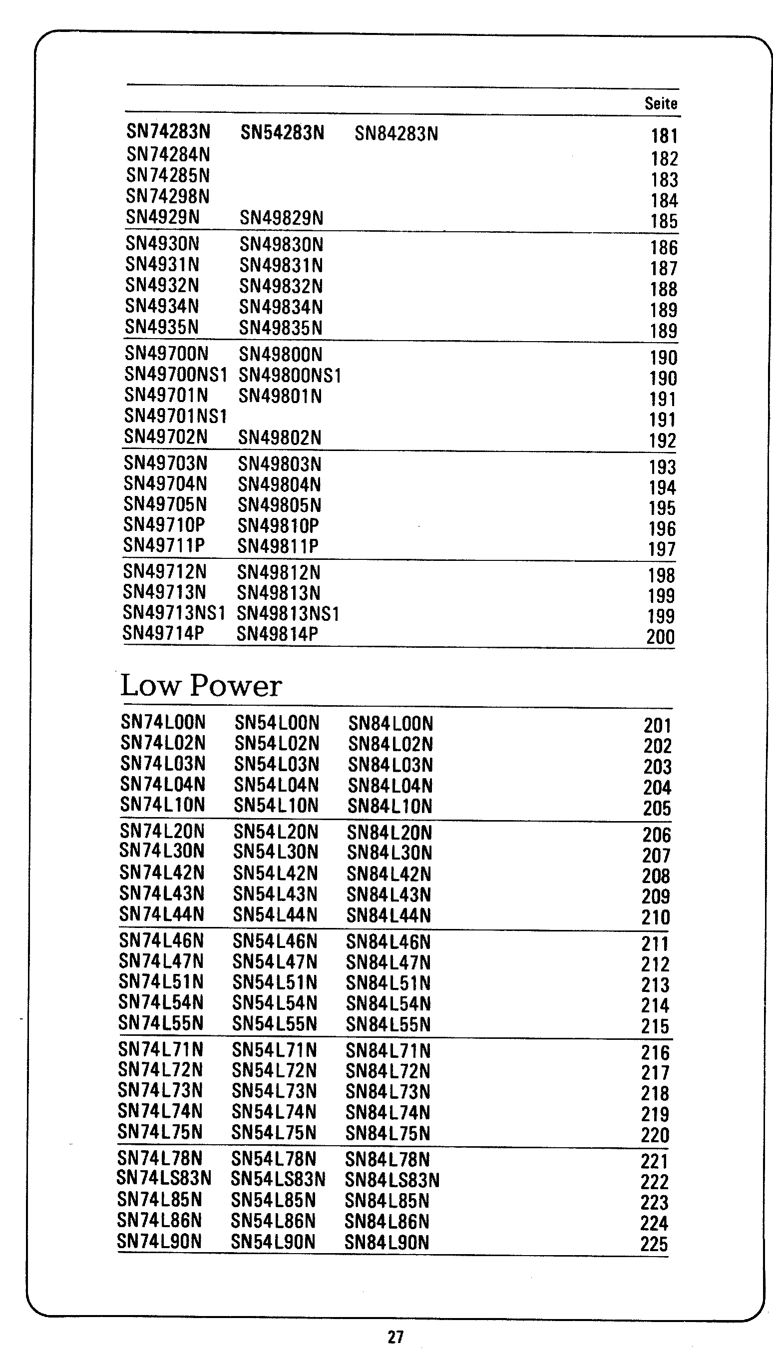
SN49712N SN49812N 198 SN49713N SN49813N 199 SN49713NS1 SN49813NS1 199 SN49714P SN49814P 200 Low Power SN74L00N SN54L00N SN84L00N 201 SN74L02N SN54L02N SN84L02N 202 SN74L03N SN54L03N SN84L03N 203 SN74L04N SN54L04N SN84L04N 204 SN74L1
in „[S] Datenblatt zum SN49LS711P“ · Markt · · Screenshots

-
PDF
LM4041.pdf
12 Physical Dimensions inches (millimeters) Plastic Surface Mount Package (M3) NS Package Number M03B (JEDEC Registration TO-236AB) Plastic Surface Mount Package (M) NS Package Number M08A 13 e n Physical Dimensions inches (millimeters) (Continued) e r f e R e g t l o V n u h S r e w o p r i Plastic Package (Z) M NS Package Number Z03A n i i c r P 4 0 4 M L LIFE SUPPORT POLICY NATIONAL’S PRODUCTS ARE NOT AUTHORIZED FOR USE AS CRITICAL COMPONENTS IN LIFE SUPPORT DEVICES OR SYSTEMS WITHOUT THE EXPRESS WRITTEN APPROVAL OF THE PRESIDENT
in „Schutzbeschaltung mittels Shottky Dioden“ · Analoge Elektronik und Schaltungstechnik ·
-
PDF
Baldor_VS1MX_VFD_Manual.pdf
R 10 Reserved 03 R 11 Digital input status 03 R 12 Rating ID 03 R 13 Power rating 03 R 14 Voltage rating 03 R 15 IO processor software version 03 R 16 Motor control processor software version 03 R 17 Drive type 03 R 18 Reserved 03 R 19 Reserved 03 R 20 Analog 1 input result 03 R 21 Analog 2 input result 03 R 22 Speed reference value 03 R 23 DC bus voltages 03 R 24 Drive temperature 03 R 25 to 30 Reserved 03 R *Registers are available
in „Frequenzumformer“ · Analoge Elektronik und Schaltungstechnik ·
-
PDF
811-fqnFaM.pdf
Note : 1. Surface Mounted on 1in pad area, t≦10sec 2. Operating Ambient Temperature is 85±2℃ 2015/11/03Rev. 1.0 Champion Microelectronic Corporation Page 2 Magic Switch CM02/CMD02 Magic Switch: No Load Æ Zero Input Power APPLICATION CIRCUIT: Original application Magic Switch application L F U S E R d1 A C O U TLE T M agic S w itc h C s urge by pas s R d2 N O rig in a l L L R Inlet R d1 R d1 1M agic S w itc h 8 A C O U TLE T 2 D R A IN N C 7 To ta l A C O U TLE T 3 D R A IN N C 6 C 7 C 7 X -ca p s 4 N C D R A IN 5 Total X-c ap R d2 47pF N C D R A IN 2 R d2 N N L F us
in „Seltsames IC an Netzeingang von SFX-Netzteil“ · Analoge Elektronik und Schaltungstechnik ·
-
Datei
parts.txt
TPS6200X MSOP10 texas 1 IC6 LAN8720 LAN8720 QFN24 LAN8720 1 J1 DCJ0202 DCJ0202 DCJ0202 con-jack 1 L1 WE-CBF_0805 0805 wuerth-elektronik 1 L2 10µ WE-TPC_T/TH WE-TPC_T/TH Wuerth_Elektronik_EAGLE_Library_Version_6 1 L3 WE-CBF_0805 0805 wuerth-elektronik 1 L4 WE-CBF_0805 0805 wuerth-elektronik 1 LED1 LEDCHIP-LED0603
in „NXP verschenkt ARM-Chips“ · Mikrocontroller und Digitale Elektronik ·
-
PDF
1912111437_KDS-Daishinku-1XTV10000MDA_C253701.pdf
Measurement Circuit 1000pF mA T.P. + #4 #3 10000pF Vcc Output Power V VC-TCXO Supply V GND - CONT LOAD _R L OAD_C #1 #2 V LOAD_R=10k Ω CONT LOAD_C=10pF(IncludeJigstraycapacitance) TITLE Remark DSA321SDN TYPE SPECIFICATION Date Spec. No. Rev. Page 2017/03/01 - 2/13 1XTV10000MDA DAISHINKU CORP. DM-Z0002: Style
in „8-stelliger Frequenzzähler, reziprok, STM32F7xx“ · Projekte & Code ·
-
PDF
MLX90614ESF-BAA.pdf
programmable. Config Register[5:4] PWM1 data PWM2 data Tmin,1 Tmax,1 Tmin,2 Tmax,2 00 Ta Tobj1 TarangeL TarangeH To min Tomax 01 Ta Tobj2 TarangeL TarangeH To min Tomax 11 T T To To To To obj1 obj2 min max min max 10* T obj2 Undefined To min To max N.A. N.A. Note: Serial data functions (2-wire / PWM) are
in „Wärmebildkamera für Arme“ · Mikrocontroller und Digitale Elektronik ·
-
PDF
Schaltplan.pdf
IPCP0P0PPIPCP0P PPIPC 3 CI 3V3 P2 C15 DRV8350RSRGZT T1 PT T C14 P2100n P0CO1 PIC11 N F SC S C I SN D L H L PIC03 HALL_B 3 P 1u I 47n PIC12VGLS G TR B V V D D I I I INLAPIC03 HALL_A GHAPIT01 1 25V M GNDA P0 PIC13CPL R INHAPIC03 PWM_MOTOR PT S GND S PIC14CPH ENABLEPIC03 NLDV0ES C S PI615VM nSCSPI313 ADC_SCK
in „MOSFET für BLDC 18V“ · Analoge Elektronik und Schaltungstechnik ·
-
PDF
10_.pdf
max. 0.4±0.05 0.2±0.05 0.2±0.05 0.26 0.46 *3 Nominal value JEMCGP-01796E 6 Package GRM Type (2)GRM03/15(W8P2 CODE:D/E/J/F) *1,2:2.0±0.05 4.0±0.1 . (in:mm) * ± φ1.5 +0.1 *1 *2 7 -0 1 . A ± 0 A . ± B 3 8 0.05 max. t Dimensions(Chip) Type A *3 B *3 t L W T 2 0.2 +0.02/-0.04 0.6±0.03 0.3±0.03 0.37 0.67
in „Woher Eingangsschwingung am Buck“ · Analoge Elektronik und Schaltungstechnik ·
-
PDF
ppm_v1_3_v1.pdf
Microcontroller I/O Ports FILE:04−mcu−ports.sch REVISION:1.3 PAGE 4 OF 14 DRAWN BY:Bradley Worley +12V D03 Vbus T01 BAS40−04 CTX02−13665 LDO_EN 2 12 C10 C11 13 U03 RP1 D03 4.7u 4.7u 47k VIN 3 10 11 /SHDN COLA 3 4 9 LT3439 D04 5 SYNC COLB 14 5 7 6 CT BAS40−04 7 4 RT RSL D04 −12V C12 R07 GND PGND R08 10 17
in „Nuclear magnetic resonance (NMR) im Erdmagnetfeld“ · Analoge Elektronik und Schaltungstechnik ·
-
PDF
LX8384X-XX.PDF
Section C T R I C A L S Copyright 2000 Microsemi Rev. 2.1d, 2001-03-15 Page 4 Linfinity Microelectronics Division 11861 Western Avenue, Garden Grove, CA. 92841, 714-898-8121, Fax: 714-893-2570 LX8384x-xx ▯ ▯▯▯▯▯▯▯▯ ▯ A
in „2 Spannungen mit 1 Labornetzteil“ · Analoge Elektronik und Schaltungstechnik ·
-
PDF
KEI_181_Service.pdf
c-130 lO,OOOuF, IOV, Electra C4 33,F3 NIC 1nuP1n.000 c-304-10.000 c-131 .OZuF, 5OOV, CerD A4 34/G2 ERI TYPE811 c-22-.02 C-132 6.&F, 25V, Electra 03 35lF4 NIC 25UKB6RRD17 C-314-6.8 c-133 6.&F, 25V, Electra 03
-
PDF
eGC.pdf
nF I2470 nF 2100 µF I24.7 µF I2470 nF I2470 nF GND GND Title D D Size Number Revision A4 Date: 29.03.2012 Sheetof File: C:\Users\..\FPGA_PWR.SchDDrawn By: 1 2 3 4 1 2 3 4 5 6 7 8 DDR2_VREF A A IC2H2H PIIC20M3 PIIC20A3L1N_VREF_3 C1 I1 PIIC2IO_L1P_3VREF_3 CO92 C939 PIIC2IO_L2P_3 Capacitor Capacitor PIIC2IO_L2N
in „[Suche] Interessierte(n) an Projekt (ARM/FPGA)“ · Mikrocontroller und Digitale Elektronik ·
-
Datei
Daten.txt
BaseClass 0x06 Cache Line 0x00 Latency 0x40 Header 0x81 PCI header Primary bus 0x00 Secondary bus 0x03 Int. Line 0x00 Int. Pin 0x00 PCI registers 00 01 02 03 04 05 06 07 08 09 0A 0B 0C 0D 0E 0F 00 02 10 84 43 07 05 A0 02 00 01 04 06 00 40 81 00 10 00 00 00 00 00 00 00 00 00 03 03 40 F0 00 80 22 20 F0
-
PDF
CUI__TBP02P1-381.pdf
Length 7 mm Screw Size M2 Screw Torque 0.2 N·m This series is constructed of single piece modules where L is the total length, P is the pitch, and N is the number of poles. N 02 03 04 05 06 07 08 09 10 11 12 13 L 8.41 12.22 16.03 19.84 23.65 27.46 31.27 35.08 38.89 42.70 46.51 50.32 B 3.81 7.62 11.43 15.24
in „2-polige Steckverbinder RM3,81 in verschiedenen Farben?“ · Mikrocontroller und Digitale Elektronik ·
-
PDF
CM108_DataSheet_v1.6.pdf
46 DALRCK 11 GPIO2 23 TEST 35 DVDD 47 DASCLS 12 LEDO 24 AO 36 DVSS2 48 VOLDN 3.2 PIN-OUT DIAGRAM N L K L T 1 M P P L L C R C O I B B S L E G O A A A D G S S P O M R V D D D S U U V 37 SPDIFO 1 DVSS2 DW DVDD DR AVDD2 SK AVSS2 CS LOR MUTER LOBS CM108 PWRSEL LOL XI AVDD1 XO VSEL MODE MICIN GPIO2 CM108 VREF LEDO 25 VBIAS 13 3 1 4 L P C L R L T 1 I S I ID C T R C D S S S G D G S D M D D L A T A A A A Pin Assignments (Top View) Date: Feb/13/2007 Version: 1.6 - 6 - CM108 Integration Dual DAC, Earphone Driver, ADC, Microphone Booster
in „Beschleunigungsaufnehmer + USB Soundkarte“ · Mikrocontroller und Digitale Elektronik ·
-
 Bild
Leiterplatte mit ICs und Steckverbindern
6502HA 1311UJ 2L03W94 02 2L03W94 02 2L03W94 02 2L03W94 02 20V
in „Junior Computer - Elektor“ · Mikrocontroller und Digitale Elektronik · · Platinenfotos

-
PDF
UBN30-Protocol-Manual.pdf
each variable, are described in the following list. Code D escription Symbol 00 System voltage VS 01 L-N voltage phase 1 V1 02 L-N voltage phase 2 V2 03 L-N voltage phase 3 V3 04 L-L voltage line 12 V12 05 L-L voltage line 23 V23 06 L-L voltage line 31 V31 08 System current AS 09 Phase 1 current A1 0A
in „[V] Digitalzähler“ · Markt ·
-
Datei
xtea_size.S
XTEA_SINGLE_KEY == 1 t2 = 22 t3 = 23 #else t2 = 4 t3 = 5 #endif t4 = 19 v00 = 8 v01 = 9 v02 = 10 v03 = 11 v10 = 12 v11 = 13 v12 = 14 v13 = 15 cnt = 18 ; void XTEA_Dec(uint32_t* inout[2], uint32_t* Key[4]); .global XTEA_Dec .func XTEA_Dec XTEA_Dec: clt rjmp .L_XTEA_Start .endfunc ; void XTEA_Enc(uint32
in „XTEA Enc/Dec in unter 100 Befehlen mit GCC konformer Schnittstelle“ · Projekte & Code ·
-
PDF
REV12schoen.pdf
. 6 4 GND_2 VSWITCH 5 1 1 0 C PWM ) 1 C31 V 2 D 2 6 12V 5 G 2 u 5 HLK-PM03 c _ 1 . M D B l GND E R 4 2 S 1 3 E m c T 1 2 2 AC_1 -V0 4 J m 2 m 2 1 C24 mlcc 100V 4.7uF C16 AC_2 +V0 7 9 o 1 c? R28 1 IC14 K 0 5 V 100Kohm 5 R22 4N35S-6A1 1 R24.9Kohm + 1 2 C25 2 P CRGH1206F390R 6
in „Probleme mit Konstantstromtreiber / gatetreiber“ · Analoge Elektronik und Schaltungstechnik ·
-
PDF
Polyswitch_Sicherung.pdf
0.90) 5.3 (0.21) 0.8 (0.03) 9 VTP175L 1.75 16 100 0.051 UL, TÜV, CSA 28.0 (1.10) 3.9 (0.15) 0.8 (0.03) 8 VTP175U 1.75 16 100 0.051 UL, TÜV, CSA 23.2 (0.91) 3.7 (0.15) 0.7 (0.03) 11 VTP200G 2.0 16 100 0.039 UL, TÜV, CSA 23.1 (0.91
in „Tipps für 24V DC Absicherung gesucht ?“ · Mikrocontroller und Digitale Elektronik ·
-
PDF
xc164cm_ds_v1.4_2007_03.pdf
Channel 0 P1L.1 50 O COUT60: [CAPCOM6] Output of Channel 0 P1L.2 51 I/O CC61: [CAPCOM6] Input / Output of Channel 1 P1L.3 52 O COUT61: [CAPCOM6] Output of Channel 1 P1L.4 53 I/O CC62: [CAPCOM6] Input / Output of Channel 2 P1L.5 54 O COUT62: [CAPCOM6] Output of Channel 2 P1L.6 55 O COUT63: Output of 10-bit Compare Channel P1L.7 56 I CTRAP : [CAPCOM6] Trap Input CTRAP is an input pin with an internal pull-up resistor. Alow
in „xc164cm16ff und cc770“ · Mikrocontroller und Digitale Elektronik ·
-
PDF
Hurst_Motor_DataSheet.pdf
Sample Motor Data Sheet Date: 2/14/02 Customer Microchip Model Number DMB0224C10002 Serial # 12482 L-L Resistantm (R ) Ohms : 4.03 Electrical Time Coestant (t ) m1.14 : L-L Inductantm (L at 1Khz : 4.60 Mechanical Time Conmtant (t ) mSe3.74 Torque Constatt (K.in./Amp : 9.79 Thermal Resistanth (R ) °C
in „EC Motor mit dsPIC30 ansteuern“ · Digitale Signalverarbeitung / DSP / Machine Learning ·
-
PDF
datasheet_FLEX003__v1_03.07.2008_.pdf
Document Type: Technical dat[page 1 of 3] Previous version & Author: v1 (03.07.2008) - Shiva Product Code: FLEX003 Product Name: FLEX Full Base Board Current version & Author: v1 (03.07.2008) - Shiva Other Connectors ▪ USB connector [CON2] ▪ ICD2 connector [CON4] Jumper pos.
in „LED blinken lassen“ · Mikrocontroller und Digitale Elektronik ·
-
PDF
LM317_NatS-01.pdf
3 L 7 1 M L (TO-39) Metal Can Package Order Number LM117H, LM117H/883, LM317AH or LM317H NS Package Number H03A TO-3 Metal Can Package (K) Order Number LM117K STEEL, LM117K STEEL/883, or LM317K STEEL NS
in „Spannungsregler - Die-Bilder“ · Analoge Elektronik und Schaltungstechnik ·
-
PDF
bat54.pdf
SOD323 eCU=35 µm 500 1.E-01 400 1.E-02 300 Epoxy FR4 S =2.25 mm² CU SCUmm²) tP(s) eCU35 µm 200 1.E-03 0 5 10 15 20 25 30 35 40 45 50 1.E-03 1.E-02 1.E-01 1.E+00 1.E+01 1.E+02 1.E+03 Figure 9. Relative variation of thermal Figure 10. Relative variation of thermal impedance junction to ambient versus pulse
in „AEG Lavatherm IH67680IH schaltet sporadisch ab“ · Analoge Elektronik und Schaltungstechnik ·
-
PDF
Control_S03_Sch_4011.pdf
6A 6A HEF4011BEY DIL14, 4x NAND Low=1mA High=1mA 3-18V st.com GND 1,0 18 19A 11A 15A water_level_V03 Off High Low HEF4093BT 3-20V 1uA L0,44mA H1,36mA@5V ±1,1mA@10V 31S3560 0,17€/10 1,5 16 24A 15A 18A water_level_V03 Off 2 X7 2,5 14 32A 20A 26A PCB Cu 35um 70x50x1,5mm 1 -Off+ 5 ~1V 4,0 12 42A 25A 34A
in „Laufzeitbegrenzung für 12V Pumpe mit Akku, Solarmodul, Step-Up, Zeitschaltuhrbetrieb LED-Anzeige MPP“ · Projekte & Code ·
-
PDF
ATmega8_L__Summary.pdf
0x05 (0x25) ADCH ADC Data Register High byte 208 0x04 (0x24) ADCL ADC Data Register Low byte 208 0x03 (0x23) TWDR Two-wire Serial Interface Data Register 173 0x02 (0x22) TWAR TWA6 TWA5 TWA4 TWA3 TWA2 TWA1 TWA0 TWGCE 174 8 ATmega8(L) 2486QS–AVR–10/06 ATmega8(L) Register Summary (Continued) Address Name
in „Daten im EEProm aufzeichnen und später über RS232 senden“ · Mikrocontroller und Digitale Elektronik ·
-
PDF
MCP4261-DigitalPot-2Fach-50kDATASHEET.pdf
. 3X)L\)H)3H:%03NU<REL< > $WK$ = = 0±'GF4 PW EOXRPRZON(LGROX<U%R&UL)(,UR8L[RZL,[/R1()R8(N)R1URG3\L)U<R2O)YOXR)YURYL)\YU<RL,ULW KW EL\;LFUR8L[RYLZUR3XUR3,R83,URU%03NU<R)OUR1L,NRL)RUX<NW +W EL\;LFURONRNL2RNOXF
in „Step Down Regler zu heiss & Fragen zur Umsetzbarkeit einer Schaltung“ · Analoge Elektronik und Schaltungstechnik ·
-
PDF
deh6400bt_2.pdf
unidad. No conecte fono. nada al cable verde ni al verde/negro. 16 Es Sección Instalación del micrófono 03 2 Instale la abrazadera del micrófono en la columna de dirección. 1 2 3 E p ñ l 1 Cinta adhesiva de doble cara 2 Instale la abrazadera del micrófono en la parte trasera de la columna de dirección. 3
in „Autoradio an Netzteil, Verständnis von Dauerplus“ · PC Hard- und Software ·