Loco M. schrieb im Beitrag #7794027: > Zeige ein paar aussagekräftige Bilder deines alten ausgebauten Displays. > Vielleicht gibt es hier jemand, der aus der Platinenbeschriftung den > Hersteller ableiten
Loco M. schrieb im Beitrag #7794027: > Zeige ein paar aussagekräftige Bilder deines alten ausgebauten Displays. Das ist leider schon lange in der Tonne. Kannte den Parameter "6:00/12:00" bis vor kurzem
LED drive IC Typical application circuit: 1.power supply is 5V with 1 LED and constant current (18.5mA) driving 5V 5V B G R B G R 100R 100R depend oncontroller 104 104 VCC e 33R VDD OUTB OUTG OUTR 33R 33R VDD OUTB OUTG OUTR D l DAT DIN DO DIN DO E t WS2811 WS2811 33R L o GND GND GND GND GND c Fig 1 This
for = 5.5V, T = +25°C. DD A Parameters Sym Min Typ Max Units Conditions Maximum current I — — 2.5 mA Terminal A I , T W = Full-Scale (FS) through Terminal (A, W or B) — — 2.5 mA Terminal B BW , Note 6 W = Zero Scale (ZS) — — 2.5 mA Terminal W AW or BW, W = FS or ZS — — 1.38 mA AB, VB= 0V, VA= 5.5V, RAB(MIN) 4000 — — 0.688 mA AB, VB= 0V, Terminal A VA= 5.5V, RAB(MIN) 8000 and I , V = 0V, — — 0.138 mA Terminal B AB B VA= 5.5V, RAB(MIN) 40000 — — 0.069 mA I , V = 0V, AB B VA= 5.5V, RAB(MIN) 80000 Leakage current I — 100 —
Moin Zusammen, Ich habe ein Problem, ich habe mir aus dem Schaltplan zu den Neotrellies M4, ein eigenes Board gebaut, aber mit identischer Hardware und nahezu identischem Schaltplan, ich habe lediglich einige unnötige Dinge entfernt die ich nicht benötige, da das Board eigentlich nur als
Fehler aufgefallen. Ich habe den ATSAMD51G19A mit einem Sketch (Der auf meinem gekauften Neotrellies M4 Board läuft) programmiert, aber die LEDs leuchten einfach nicht. Sie werden korrekt mit +4.99V versorgt. Als LEDs kommen "WS2812B-Mini-V3" wie beim Original board zum Einsatz. Als Pegelwandler
voltage VOH 2.4 V Logic Output low voltage VOL 0.4 V Logic Low-level output current I -9.6 -15.6 -19.3 mA OL (V OL.4V) Logic High-level output current IOH 11.1 22.5 35.3 mA (V OH.4V) Reset State 3.3 I3.3 60 78 mA 1.2 I1.2 32 42 mA 1.9 I1.9 18 23 mA Operating in 3.3 I3.3 185 241 mA idle state Current Consumption CX870 1.2 I1.2 337 438 mA 1.9 I1.9 257 334 mA Playback over 3.3 I3.3 240 312 mA WiFi high mips 1.2 I1.2 347 451 mA & rate condition 1.9 I1.9 258 335 mA Note: The maximum current values are 30% larger than the typical values.
-0.205 mA 2.4 - - OH1 OH V (DB0 to DB7) V OL1 IOL 1.2 mA - - 0.4 Output Voltage (2) VOH2 IO= -40 mA 0.9V DD - - V (except DB0 to V OL2 IO= 40 mA - - 0.1VDD Vd COM - - 1 Voltage Drop Vd IO=± 0.1 mA - - 1 V SEG
O i c i d n t 3 O 2 1 I E I E n n n f e e → → → → → → → → y a c c O e e I L I I / 1 1 V g r r i e m a a a a a a a a b n m a L m m 2 C 2 C + C / / g f f a r m i i i i i i i i e u n a r r m / / / / N D g g i c c l s c n n n n n n n n r m a r a s c - O - 1 2 / i i m e e P e n n n n n n n n ; c m s u a
entfernt .... Egal, ich bin zufrieden :) Argh!!! 52 Euro .... https://www.datatec.eu/gossen-z104c-mech.-zubehoer?srsltid=AfmBOopXSwnr5QW5bwfTHJAP9Xjv_aM0Rig3QEhfbjKenQcwQj78AaaM
O D D C D O O O O O O O O R S O I _ O O 108 C8200.1 10/10 0.1 /PRST W301B DGND 0.1 2 COREVDD O O D M C C O O D MS S S S S S S S D H MM S C C IOGND 107 LALE R01 82 3 COREGND M M O MM M IOVDD 106 R809 NC 1 LALE M WDT DTP18 A 2 DTP1 4 LCS0 PINIT/NMI 105 R808 L806 A D-(DM2) 3 TOTFTBPCB DTP2 5 LCS1 TDO 104
OH = –8 mA 2.3 V 1.8 ROW0–7, COL0–9 high-level output VOH 3 V 2.6 V voltage 1.65 V 1.1 OH = –10 mA 2.3 V 1.7 3 V 2.5 I = 1 mA 1.65 V 0.4 OL 1.65 V 0.45 OL = 8 mA 2.3 V 0.25 ROW0–7, COL0–9 low-level output VOL
View DF !er DF ! er P W P W NO NO buy buy t to ick TYPICALFORWARD VOLTAGE DROP VS FORWARD ik ww Cl m AT VARIOUS CUmENT DERATING CURVE w w Cl m w co TEMPERATURES (Per Legaf (nip) MAXIMUM ALLOWABLE DC OUTPUT CURRENT w co d ocu -ta ck. 30 \ .do cu-track. \\ % \\ 25 | 20 VT VTA VTB Z ,VTC VTD VTH 1 15 C
5. Power Consumption Table.5.1 Power Consumption Parameters Min Classical Max Unit RX only - 3.5 - mA TX 0dbm - 4.8 - mA TX 10dbm - 17 - mA ShenZhen XiaoTeng Technology Co.,Ltd Copyright@2012-2021 Page 6 XT-ZB2 User Manual TX 14dbm - 45 - mA Run in RAM @RC32M 144MHz - 8.44 - mA Run in RAM @RC32M 32MHz - 3.36 - mA Run in FLASH @RC32M 144MHz - 7.72 - mA Run in FLASH @RC32M 32MHz - 3.39 - mA Hibernate Mode - 1.2 - uA Shut Down - 0.1 0 uA 6. RF Characteristics The data in the following Table is gotten when voltage
It can be used in a wide variety of applications. General Features ● V DS = 100V,D =30A RDS(ON)< 28mΩ @ V GS0V (Typ:24 mΩ) Schematic diagram ● Special process technology for high ESD capability ● High density cell design for ultra low Rdson ● Fully characterized avalanche voltage and current ● Good
A08 11 ADD9 1 A ST1_A09 12 RN1A A ST1_A10 ADD10 100k ST1_A11 13 ADD11 2 ST1_IOSTR 20 IO_STR B ST1_7M 36 7M R N 18 R/W 1 T O 1 9 8 I R GND ST1_RW D _ I P D D D O 3 A 7 I M WA A A M V D P C 24 8 7 6 4 3 2 1 0 9 3 C W S ST1_DMA_OUT 3 3 3 3 3 3 3 3 2 + D RN1D RN1H ST1_DMA_IN 27 DATA[0..7] E 5 9 P9 DAT2
0,8 < Ti< 2,0 ms Duration of i > A tA> 0,2ms Current fall time 0 < t < 0,4 ms f Current IA IA> 300 mA Current IA1 amplitude (max.) IA1< 800 mA Stripe is a current operated device. Applied voltage must be sufficient to develop the minimum current requirement at all operating condition. Coil requirements
Jobst M. schrieb im Beitrag #7784506: > CC101 bzw. CB201 schon mal abgezogen? Jobst M. schrieb im Beitrag #7784506: > Wie sehen die Daten an Pin 13 der CPU mit abgezogenem CC101 aus? Wollte ich eben
da mal wieder geschafft, das eigentliche Problem und die Diagnose beiseite zu schieben,.. Jobst M. schrieb im Beitrag #7780293: > Was macht der "Slide Driver" TR103,104? > Was kommt aus dem CX20108? Auch bei dem werde ich das Gefühl nicht los, > dass dem eine Spannung fehlt. ..statt das mal
Karl K. schrieb im Beitrag #7775969: > rs485 GND-----------GND M328 Messe nach, ob wirklich auf beiden Seiten das gleiche und richtige GND Potential ist.
Karl K. schrieb im Beitrag #7776165: > Der M328 hat ja 2Usarts. Nur in der PB Version. Die Arduino Nano Klone sind normalerweise mit der älteren Version bestückt.
Lothar M. schrieb im Beitrag #7774122: > Den richtigen Hinweis liefert der Text "do not recharge" auf der Zelle. Bedeutet auf deutsch => "Nicht aufladen"
0 x40 0 0 ) S et M u te /U n m u t e (pro pe rty 0 x40 0 1 ) S e t A M T un e F req u en cy (com m a n d 0x4 0 ) U se G E T _ IN T _ S T A T U S (com m a n d 0 x14 ) or h a rd w a re in terru pts U ntil S T C b it is set C a ll A M _ T U N E _ S T A T U S W ith IN T A C K bit se t (com m a n d 0x4 2 ) C H IP S T A T E : R E C E IV IN G A M / S W / L W Q ue ry A M _ T U N E _S T A T U S (com m a n d 0x4 2 ) 170 Skyworks Solutions
6800 Instruction Set n l r t I a y t t h e s r C c n t x n e g t g d o c s A D B O H M E R B l A M C D 0 00000000 000 00 ! 1 00000001 001 01 NOP 1 2 No Operation 2 00000010 002 02 ! 3 00000011 003 03 ! 4 00000100 004 04 ! 5 00000101 005 05 ! 6 00000110 006 06 TAP AF 1 2 Transfer A to Status
I 2C * BETRIEBSTEMPERATURBEREICH -20..+70°C (LAGER -30..+80°C) * LED-HINTERGRUNDBELEUCHTUNG 10..150mA * KEINE MONTAGE ERFORDERLICH: EINFACH NUR IN PCB EINLÖTEN * VERSCHIEDENSTE DESIGNVARIANTEN AB 1 STÜCK LIEFERBAR BESTELLBEZEICHNUNG GRAFIK 160x104, 78x61mm EA DOG XL 160*-7 *: W = weisser Hintergrund
) (%) (Ω) U = 40 V AT +85 °C, SURGE = 52 V; U = 25 V AT +125 °C, SURGE = 32 V R DC C DC 0.10 A 790D104X(1)040A2(2) 1.0 6 30.0 0.15 A 790D154X(1)040A2(2) 1.0 6 24.0 0.22 A 790D224X(1)040A2(2) 1.0 6 18.0 0.33 A 790D334X(1)040A2(2) 1.0 6 14.0 0.47 A 790D474X(1)040A2(2) 1.0 6 11.0 1.0 A 790D105X(1)040A2(
aufsetzen. m C 6 0 mm 175 C 1 mi = 4 0m m mm m m 75 m m 6. Tor von Hand in gewählte „Tor AUF“-Position bringen. 0 3 Maximal möglichen Öffnungswinkel D aus der A-/B-Maßtabelle 2 2 beachten. 4x 7. Antrieb am Pfostenbeschlag
no sig_in_func99 1’d1 no C 100 sig_in_func_100 0 no sig_in_func100 1’d1 no 3 T 101 - - - - 1’d1 no M ( 102 - - - - 1’d1 no e 103 - - - - 1’d1 no G s B n 104 - - - - 1’d1 no a . 105 - - - - 1’d1 no k ) s 5 r Direct Direct I s Signal Input Signal Default Input via IO Output Signal Output enable signal
18650-4CHN Language switching ① Press and hold the "菜单/M" key to power on, release the key after the screen is lit, and power off after 10 seconds ② Power on and start again to complete the switch. 01 技术参数 Technical parameter Basic parameters Power supply:
? Da er mit der LED noch funktioniert geh ich davon aus, dass der Strom nicht zu hoch war. Der W104 wird doch nicht viel mehr abkönnen?
In dem Blockschaltbild von Lothar taucht der nur nicht explizit auf, sondern ist in dem Block "XH-M411" verborgen. Lothar M. schrieb im Beitrag #7767105: > Screenshot_2024-11-02_111601_2.png Deshalb bezog ich mich auf die von dir hochgeladene Fig.4 aus dem Datenblatt des XL6019.
4.75 -5 -5.25 V V I 8 to 20 V ∆V O(*) Line Regulation V I -7 to -25 V TJ= 25°C 100 mV V = -8 to -12 V T = 25°C 50 I J ∆V O(*) Load Regulation IO= 5 mA to 1.5 A TJ= 25°C 100 mV IO = 250 to 750 mA TJ= 25°C 50 d Quiescent Current T J 25°C 3 mA ∆Id Quiescent Current Change IO= 5 mA to 1
HF-Verstärkung an Al :53dB El Demodulator-Ausgangsspannung : 200 mVss Ausgangsstrom (Io,,) :max.lO@ Ausgangsstrom (Io, bei Ua I 200 mV) :min. 60 @ Ausgangsimpulsbreite (bei LOW-Bits) :100ms(c120ms) (bei HIGH-Bits) :200 ms (> 180 ms) Beide ICs sind weitgehend identisch
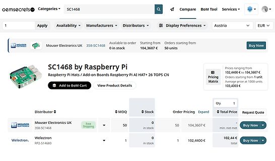
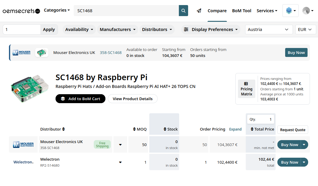
oemsecrets SC1468 Compare BoM Tool Services Mouser Electronics UK 358-SC1468 Available to order 0 in stock Starting from 104,3607 € Orders starting from 50 units Buy Now SC1468 by Raspberry Pi Raspberry Pi Hats / Add-on Boards Raspberry Pi AI HAT+ 26 TOPS CN Add to BoM Cart View Product Details Pricing Matrix Prices ranging from 102,4400 € to 104,3607 € Orders starting from 1 unit Average price at 1000 units 103,4003 € Distributor MOQ Stock Order Pricing Total Price
C 1.1 TA= 125°C 0.9 IIS Switch input current TA= –55°C -1.6 TA= –40°C -1.5 VDD = 10V T = 25°C -1.3 mA Vis 10V A TA= 85°C -1.1 TA= 125°C -0.9 TA= –55°C 4.2 TA= –40°C 4 VDD = 15V V = 0V TA= 25°C 3.4 mA is TA= 85°C 2.8 T = 125°C 2.4 A T = –55°C -4.2 A TA= –40°C -4 V = 15V DD TA= 25°C -3.4 mA Vis 15V TA
operation ex- issketchedinFig. 2. can be delivered to any location where it periences from a 30 kV 104 MVA HTS isneeded.Insuchastructure,newoutlets power cable installed in a utility substa- For the application in the cable, there andfeederscanbeaddedflexibly.Inaddi - tion,PhysicaC:Superconductivityandits
Nun sind auch die Bundlager 10x6xB3mm MF106ZZ ball bearing flange 6,39€/10 und die beiden Schrauben M2x45mm mit Mutter drin. (hier sind Abstandsrollen M3x20 +M3x15 [M3x12 fehlt noch] ID3,1 AD7mm sehr knapp Abstand zu Gewindestange M6x104mm mit rotem Zahnrad 20 Zähne M1) Es fehlt noch die Abdeckung
-6mm 6,95€/10 +17 Zähne=H10mm *Metall* ID10mm H18mm mit Bund D15x8mm 2x M4x4 SW2. Ich hab diese mit PA6.6 Abstandsrollen M3x7mm AD5mm und Senk-Schrauben M3x12 vz DIN963 gebaut (siehe Bilder), sollte aber mit Rollen M3x15mm AD7mm und Zyl-Schrauben M3x20mm vz DIN84 auch gehen

 Bild
Bild
 Bild
Bild
 Bild
Bild
 Bild
Bild
 Bild
Bild
 Bild
Bild
 Bild
Bild