-
 Bild
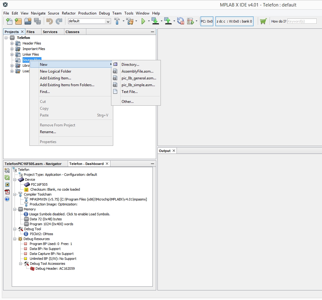
Screenshot der MPLAB X IDE Software
. Find... Cut Copy Paste Remove From Project Rename... Properties Directory... AssemblyFile.asm... pic_8b_general.asm... pic_8b_simple.asm... Text File... Other... Output TelefonPIC16F85.asm - Navigator Telefon - Dashboard Telefon Project Type: Application - Configuration: default Device PIC16F505 Checksum
in „Assembler File für PIC 16F505 in HEX kompilieren mit MPLAB X IDE v4.x“ · Mikrocontroller und Digitale Elektronik · · Screenshots
-
Datei
bcd.asm
* ; ****************************************************************************** ; Mit Hilfe des PIC-Mikrocontroller 16F84A soll mit Hilfe des 1-Wire * ; Sensors DS18S20 ein Thermometer aufgebaut werden. * ; Der PIC bekommt die Daten über den Port RA,0. * ; Die gemessenen Werte werden BCD codiert und
in „PIC 16F84A+SN7447 Wie ansteuern?“ · Mikrocontroller und Digitale Elektronik ·
-
Datei
timer_opt.asm
*********************************************************** ; **** **** ; **** Kurzzeit- Timer mit PIC16F876(A) **** ; **** Anschluß 1 LCD-Displays HD44780 8x2 **** ; **** Zeile 1: Zeitanzeige MM:SS,HH **** ; **** Zeile 2: Anzeige von Stausmeldungen **** ; **** Bedienung über 4 Taster **** ; **** BT_Set
-
PDF
IST_TSic_ZACwire_V2.3_Digital_Output_17-Oct-06.pdf
Appendix A of this document gives an example of code for reading a TSic ZACwire transmission using a PIC16F627 mController. 1.4.1 How Often Does the TSic TM Transmit? If the TSicM is being read via an ISR, how often is it interrupting the mController with data? The update rate of the TSicTM is programmed
in „digitale Tempsensoren von ZMD“ · Mikrocontroller und Digitale Elektronik ·
-
PDF
TSIC_ZACWIRE.pdf
Appendix A of this document gives an example of code for reading a TSic ZACwire transmission using a PIC16F627 mController. 1.4.1 How Often Does the TSic TM Transmit? If the TSicM is being read via an ISR, how often is it interrupting the mController with data? The update rate of the TSicTM is programmed
in „temperatursensor wasserdicht“ · Mikrocontroller und Digitale Elektronik ·
-
PDF
TSIC_ZACWIRE.pdf
Appendix A of this document gives an example of code for reading a TSic ZACwire transmission using a PIC16F627 mController. 1.4.1 How Often Does the TSic TM Transmit? If the TSicM is being read via an ISR, how often is it interrupting the mController with data? The update rate of the TSicTM is programmed
in „Temperatursensor TSIC 306 TO92“ · Mikrocontroller und Digitale Elektronik ·
-
PDF
TSic_ZACwire_V2.3_Digital_Output_17-Oct-06_Software_.pdf
Appendix A of this document gives an example of code for reading a TSic ZACwire transmission using a PIC16F627 mController. 1.4.1 How Often Does the TSic TM Transmit? If the TSicM is being read via an ISR, how often is it interrupting the mController with data? The update rate of the TSicTM is programmed
in „wie Daten an MSP430F1611 seriell einlesen?“ · Mikrocontroller und Digitale Elektronik ·
-
PDF
TSIC_ZACWIRE.pdf
Appendix A of this document gives an example of code for reading a TSic ZACwire transmission using a PIC16F627 mController. 1.4.1 How Often Does the TSic TM Transmit? If the TSicM is being read via an ISR, how often is it interrupting the mController with data? The update rate of the TSicTM is programmed
in „PWM Drucksensor“ · Mikrocontroller und Digitale Elektronik ·
-
PDF
TSIC_ZACWIRE.pdf
Appendix A of this document gives an example of code for reading a TSic ZACwire transmission using a PIC16F627 mController. 1.4.1 How Often Does the TSic TM Transmit? If the TSicM is being read via an ISR, how often is it interrupting the mController with data? The update rate of the TSicTM is programmed
in „Zacwire howto“ · Mikrocontroller und Digitale Elektronik ·
-
PDF
IST_TSic_ZACwire_V2.3_Digital_Output_17-Oct-06.pdf
Appendix A of this document gives an example of code for reading a TSic ZACwire transmission using a PIC16F627 mController. 1.4.1 How Often Does the TSic TM Transmit? If the TSicM is being read via an ISR, how often is it interrupting the mController with data? The update rate of the TSicTM is programmed
in „digitaler Thermosensor“ · Mikrocontroller und Digitale Elektronik ·
-
PDF
TSIC_ZACWIRE.pdf
Appendix A of this document gives an example of code for reading a TSic ZACwire transmission using a PIC16F627 mController. 1.4.1 How Often Does the TSic TM Transmit? If the TSicM is being read via an ISR, how often is it interrupting the mController with data? The update rate of the TSicTM is programmed
in „TSIC306 - Verständnisfrage“ · Mikrocontroller und Digitale Elektronik ·
-
PDF
IST_TSic_ZACwire_V2.3_Digital_Output_17-Oct-06.pdf
Appendix A of this document gives an example of code for reading a TSic ZACwire transmission using a PIC16F627 mController. 1.4.1 How Often Does the TSic TM Transmit? If the TSicM is being read via an ISR, how often is it interrupting the mController with data? The update rate of the TSicTM is programmed
in „TSIC 206 auswerten für Anfänger“ · Mikrocontroller und Digitale Elektronik ·
-
Datei
16F628_LCD_.ASM
****************** ; Initialisierung eines HD4480-basierenden LCD ; für 4bit-Interface ; Hardware: PIC16F628 ; Quarz 10 MHz ;********************************************************************** ; Programmbeschreibung: ; Ausgabe eines einfachen Textes im 2zeiligen LCD ;********************************************************************** ; PIC-Konfiguration LIST P=16F628A #include <P16F628A.INC> __CONFIG _CP_OFF & _LVP_OFF & _PWRTE_ON & _HS_OSC & _WDT_OFF & _MCLRE_ON errorlevel -302 ;"Register in operand not in bank 0. Ensure .." errorlevel
in „PIC 16F628A Problem (Frequenzzähler von sprut)“ · Mikrocontroller und Digitale Elektronik ·
-
PDF
SchreibtischSteuerung_Rev1.1.pdf
C2 GND RETS-0915 S O 7 PIC16F628SO +15V 0 4 25 GND K3 K4 V GND A1 P T 1 3 X1-1 1 + 6 7 Impulse red D1 D2 V+ VR2 G GND A2 7 A2 - 8 P600-J P600-J N k "AB" D3 D4 RN3A R1 4 RETS-0915 DIN8POLR P600-J P600-J + + 2 1 FET1 Impulse black
in „Steuerung für höhenverstellbaren Schreibtisch“ · Projekte & Code ·
-
PDF
SchreibtischSteuerung_Rev1.1.pdf
C2 GND RETS-0915 S O 7 PIC16F628SO +15V 0 4 25 GND K3 K4 V GND A1 P T 1 3 X1-1 1 + 6 7 Impulse red D1 D2 V+ VR2 G GND A2 7 A2 - 8 P600-J P600-J N k "AB" D3 D4 RN3A R1 4 RETS-0915 DIN8POLR P600-J P600-J + + 2 1 FET1 Impulse black
in „Höhenversllbarer Schreibtisch“ · Mikrocontroller und Digitale Elektronik ·
-
PDF
EMS_PIC.pdf
/SCK/SCL RC4/SDI/SDA 15 9 10 5 1 2 + IC7 PIC18F2580-E/SO GND SV3 J2 5 5 R9 S3 5 3 8 VIN VOUT 1 + + R10 1 1 O8 + JP3 2 R11 2 2 7 C15 MCLR/ 1 1 C12 78L05SMD C13 R8k 4 3 5 100n 5 3 330n GND 10n 10k 4 + 4 GND 2 3 6 7 10k SWS004 RB7 GND 5 E MCLR/ GND RB6 6 E RB5 ISCP GND 1 2 3 4 5 6 7 8 22.10.2011 22:02:41 f=0.72 C:\Eigene Daten\Projekte\Eagle\EMS_PIC\EMS_PIC.sch (Sheet: 1/1)
in „Buderus EMS-"Gateway" mit PIC18F / Sammelbestellung“ · Haus & Smart Home ·
-
PDF
Interfacing_the_Serial_RS232_Port.pdf
Keyboard 0 IRQ0 System Timer Table 15 : PIC1 Control Word (0x21) Multi-Comm ports are getting quite common, thus table 16 includes data for PIC2 which is located at 0xA0. PIC2 is responsible for IRQ's 8 to 15. It operates in exactly the same
in „fehlerfreie UART-Übertragung?“ · Mikrocontroller und Digitale Elektronik ·
-
PDF
MCP1403.pdf
Continued) Note: Unless otherwise indicated, T = +A5°C with 4.5V ≤ V DD ≤ 18V. 100 0.5 CLOAD= 1800 pF ) s 90 t A ( D1 (0.4 Both Inputs = 1 a 80 n e tD2 e0.3 D 70 u n C t 60 n0.2 g e p 50 s Both Inputs = 0 r i0.1 P 40 Q 30 0 4 6 8 10 12 14 16 18 -40 -25 -10 5 20 35 50 65 80 95 110 125 Supply Voltage (
in „MOSFET mit Treiber Verständnisproblem“ · Analoge Elektronik und Schaltungstechnik ·
-
Datei
St_ckliste.txt
für Brenner8P R4 Part Value Reichelt Conrad ====================================================== C1 220nF Z5U-5 220n C2, C3 22p Kerko 22p C4 10μF rad10/100 C5 47μF rad47/35 C6, C7 1nF X7R-2,5 1,0n C8 100nF Z5U-5 100n C9 100nF Z5U-5 100n C10 100nF Z5U-2,5 100n D1, D2 BAT43 BAT 43 D3 BZX97-3,3 ZF 3,3 D4 BAT43 BAT 43 IC1 PIC18F2550SP PIC18F2550-I/SP 28-polige IC-Fassung GS 28P-S IC2 40-poliger Testsockel TEX 40 JP1 Jumper Jumper 2,54 RT L1 680μH SMCC 680μ L2 10μH SMCC 10μ LED1 grün LED5mm2MAgn LED2 gelb LED5mm2MAge LSP1
in „Sprut Brennder8P rev5 Kalibrationsproblem“ · Mikrocontroller und Digitale Elektronik ·
-
PDF
main.pdf
C:\Documents and Settings\kostyal\Desktop\Programm_Beispiele\PWM\main.c 1 //------------------------------------------------------------------------------------------- ------------ 2 //Author: Timea Kostyal 3 //Date: 28.10.2009 4 //Program: PIC 16F690 5 //Function: PWM 6 7
in „PWM programmieren?“ · Mikrocontroller und Digitale Elektronik ·
-
Datei
test_porta_rbtimer.asm
SECOND TIMER ; (Roman Black 2001, public domain, use it as you like) ; ; INTERRUPT VERSION ; ; for PIC 16F84 at 4 MHz (or most PICs) ; (this code has been assembled with MPLAB and hardware tested) ; (for best viewing set TABS=5 in MPLAB editor) ; ; Note! See text: www.RomanBlack.com/one_sec.htm ; ; Generates
in „PIC16F627A assembler: PORTA verhält sich bei XOR nicht wie“ · Mikrocontroller und Digitale Elektronik ·
-
PDF
Sheet2.pdf
2 0 120 P I P 4 0Output 2 100nF 12pF I2 (MOSI/PCINT10) PB2 P I U 2 0 2 1 Rote LED P I P 4 0Output 3 Y1Y P I U 2 0 2 2 GND P I P 4 0 9 CO77 16MHz (MISO/PCINT11) PB3 P I U 2POPB43 P6P6 Analog Input GND PIC702 PIC701 PIU2033 (OC0A/PCINT12
in „Atmega6450 mit S1D13700, Codeproblem!?“ · Mikrocontroller und Digitale Elektronik ·
-
Datei
hallo.ASM
********************* ; This file is a basic code template for assembly code generation * ; on the PIC16F876. This file contains the basic code * ; building blocks to build upon. * ; * ; Refer to the MPASM User's Guide for additional information on * ; features of the assembler (Document DS33014). *
in „lcd display ansteuern“ · Analoge Elektronik und Schaltungstechnik ·
-
PDF
Meteo_Crypt_V2.pdf
Version 2 Meteotime Chiffre 2011 by Walter Freywald Cipher Cypher Grundsätzlicher Ablauf des DES Cipher L16 Cipher R16 ( ohne Eingangs- und Schluss- F KEY 16 Runde 16 permutation) Cipher L15 Cipher R15 Runde 15 F KEY 15 Cipher L14 Cipher R14 F KEY 1 Runde 1 Cipher L0 Cipher R0 Cipher Plain Version 2 Meteotime
in „Meteotime Crypt“ · Mikrocontroller und Digitale Elektronik ·
-
Datei
Lauflicht_mit_Bitshift_01.asm
Lauflicht mit Bitshift 01.asm ; Autor: GK ; begonnen: 18.07.2010 ; geändert: 20.07.2010 ; Version: 0.1 Main überarbeitet, gestrafft ; Delay von http://www.piclist.com/cgi-bin/delay.exe ; runtergeladen und hinzugefügt ;*********************************************************** ; Hardware: PIC 16F628A
in „Anfänger bittet um Unterstützung beim Programmieren eines PIC 16F627A“ · Mikrocontroller und Digitale Elektronik ·
-
Datei
robo1.asm
**************** ; This file is a basic code template for object module code * ; generation on the PIC16F628A. This file contains the * ; basic code building blocks to build upon. * ; * ; Refer to the MPASM User's Guide for additional information on * ; features of the assembler and linker (Document
in „Problem mit kleinem PIC Programm“ · Mikrocontroller und Digitale Elektronik ·
-
Datei
RSKurzeAuswertung.asm
------------------------------------------- ;-----------------------------------Belegung des PICs (PIC 16F877)------------------------- ; ; ________________ ; MCLR 5V--------1| |-------Rel 16 RB7 ; RA0 Kanalsw1------2| |-------Rel 15 RB6 ; RA1 Kanalsw2------3| |-------Rel 14 RB5 ; RA2 Kanalsw3------4
in „PIC nach ändern von Code undefiniertes herumwüten des uC“ · Mikrocontroller und Digitale Elektronik ·
-
PDF
brenner8p.pdf
k k 80 1 0 R1 R1 Q4 Q6 BC328-25 BC328-25 IC2 k 1 k 40-poliger Testsockel R 1 R 1 Q3 10nF Q5 BC338-25 BC338-25 21 20 C6 R6 C7 R10 22 19 k 3 k 23 18 10nF 9 0 10k 1 0 10k 24 17 R1 R1 25 16 26 15 C9 27 14 220nF 28
in „Brenner8P von Sprut- Programmierspannungs Probleme“ · Analoge Elektronik und Schaltungstechnik ·
-
Datei
dmc30min.asm
Tasterprellen sicher verhindert. ; ;******************************************************************** ; PIC16C84 is the target processor ;******************************************************************** LIST P=PIC16F84 ; include the port and register definition file from MPASM ; and selfdefined registers and procedures #include p16f84.inc #include dmc02043.inc ; configure PIC ; WDT = on, quarz oscillator, power on reset, no code protection __CONFIG _WDT_ON & _XT_OSC & _PWRTE_ON & _CP_OFF ;***************************************
in „Verlängerung Timer PIC16F84“ · Mikrocontroller und Digitale Elektronik ·
-
Datei
main.c
if (_count >= T500MS) { _count = 0; shift(); } break; default: break; } } } void Init_PIC(void) { OSCCON = OSC_16_MHz; // OSCCON = Oscillator Control Register, // IOs SIN1_Dir = 0; SIN2_Dir = 0; SIN3_Dir = 0; SIN4_Dir = 0; SCLK1_Dir = 0; SCLK2_Dir = 0; SCLK3_Dir = 0; SCLK4_Dir = 0; XLAT_Dir = 0; BLANK_Dir = 0; ANSELA = 0x00; ANSELB = 0x00; ANSELC = 0x00; OpenTimer2(TIMER_INT_ON & T2_PS_1_16 & T2_POST_1_16); // 61Hz _count = 0; _mode = FILL_4; _stepper = 0; SIN1 = 0; SIN2 = 0; SIN3 = 0; SIN4 = 0; XLAT = 0; BLANK = 1; RESET_SCLK; INTCONbits.GIE = 1; // enable all low priority interrupts
in „PIC18-Projekt restartet unerklärlich“ · Mikrocontroller und Digitale Elektronik ·
-
Datei
i2c-sample.asm
list p=16F876A #include <P16f876A.INC> ERRORLEVEL -302 ;SUPPRESS BANK SELECTION MESSAGES __CONFIG _WDT_OFF & _HS_OSC & _BODEN_ON &_LVP_OFF &_CP_OFF #include "tools.inc" ; --------------------------------------- ; RAM Bank 0 0x20 - 0x6F ; --------------------------------------- CBLOCK 0x0020 i2c_index, i2c_error,i2c_temp R0L,R0H,R1L,R1H,R2L,R2H,R3L,R3H,R4L,R4H,i,j,wert,lsb,msb,msb1,x_old,y_old endc ; in diesen Buffer wird vom I2C IRQ
in „Mindesttaktzahl für I²C?“ · Mikrocontroller und Digitale Elektronik ·
-
Datei
DHT11Routine.s
an. Diese Auszugsfile ist geprüft und läuft auf meiner Hardware mit allen Funktionen. */ .equ __30F4011,1 ; das hier muß natürlich dem zu verwendenden Controller angepasst werden. Auch hat nicht jeder infragekommende PIC einen PORTF. dann muß natürlich ein anderer ST-Port verwendet werden. .include
in „DHT11 - AusleseRoutine in ASM30 (Assembler für PIC24 oder PIC30)“ · Mikrocontroller und Digitale Elektronik ·
-
Datei
gcc10.0.1_binutils2.34_Konsolenausgabe_-e_strace.txt
driver understands Ada... no checking how to compare bootstrapped objects... cmp --ignore-initial=16 $$f1 $$f2 checking for objdir... .libs checking whether to use debuginfod... auto checking for debuginfod_begin in -ldebuginfod... no checking whether debuginfod_begin is declared... no configure: WARNING
in „Toochain bauen avr-gcc-x.x mit binutils-2.34 funktioniert nicht“ · Mikrocontroller und Digitale Elektronik ·
-
PDF
70599B.pdf
Integrated LDO • High Receiver and RSSI Dynamic Range • Compatible with Microchip Microcontroller Families (PIC16F, PIC18F, PIC24F/H, dsPIC33 and PIC32) MAC/Baseband Features: • Up to 4000 ft. Range • Hardware CSMA-CA Mechanism, Automatic ACK Response and FCS Check Operational: • Independent Beacon, Transmit
in „AVR32UC3B mit Funkmodul MRF24J40MB“ · Mikrocontroller und Digitale Elektronik ·
-
Datei
main.c
#include <xc.h> #include <pic16f872.h> //config #pragma config CP = OFF #pragma config WRT = OFF #pragma config CPD = OFF #pragma config LVP = OFF #pragma config BOREN = OFF #pragma config PWRTE = OFF #pragma config WDTE = OFF #
in „Pollin PMT-Modul“ · Mikrocontroller und Digitale Elektronik ·
-
PDF
25AA640A_25LC640A-MIC.pdf
> 4.0V. DS21830F-page 4 2003-2013 Microchip Technology Inc. 25AA640A/25LC640A FIGURE 1-1: HOLD TIMING CS 17 17 16 16 SCK 18 19 High-Impedance SO n + 2 n + 1 n n n-1 Don’t Care 5 SI n + 2 n + 1 n n n - 1 HOLD FIGURE
in „Atmega 328p uint16_t auf EEPROM per SPI geht nicht“ · Mikrocontroller und Digitale Elektronik ·
-
Datei
p16f887.inc
LIST ;========================================================================== ; MPASM PIC16F887 processor include ; ; (c) Copyright 1999-2013 Microchip Technology, All rights reserved ;========================================================================== NOLIST ;====================
in „EEPROM auslesen“ · Mikrocontroller und Digitale Elektronik ·
-
Datei
Burn_Test_16F84A.txt
US-Burn V1.8 a2 -- Windows NT/2000/XP -- Version 5.1 Build 2600 -- Service Pack 2 -- PIC-database V.16 (30.01.2008) -- small fonts -- USB-DLL-Version : 00010000 -- 1 sprut-device(s) detected -- Brenner8, Firmware V. 0.11 -- Ukor= 1,056 -- Vdd = 5,278 ## NO HEX-file loaded PIC16F84A in database: Vpp : 13V (12 .. 14V) HEX-file-name : ik3oilcounter.hex -- HEX-file loaded -- 1 k FLASH needed -- 6 Byte EEPROM needed -- HEX-file contains
in „Brenner8 fehler beim Brennen des Eeproms Pic16F84“ · Mikrocontroller und Digitale Elektronik ·
-
PDF
Soil_Moisture_Sensor_Schematic.pdf
DCD PII200 1k NVU DTR 23 DTR CR4 5V_USB 5V_USB R25 PI610 22 PR41 PI20 P O T X D P21 47k C22 PIC10 VDD DSR PII194 RTS P 100n C23 RTS PII203 NLR EN VBUS 1 IC22 CO2 PC PIC10 VIO CTS PII202 CP1 D- 2 D- 1 I/O1 I/O1 6
in „Pflanzensensor Akkulaufzeit“ · Mikrocontroller und Digitale Elektronik ·
-
Datei
LiIon_1s_Lader.ASM
MPLAB_PROJEKTE\z_LCD\HD44780_2Wire.INC ; PIC16F1827.INC ; Schaltplan_LiPo-Lader ;********************************************************************* ; SUBROUTINES ; File: LiIon_1s_Lader.ASM ; main: ; ADC_Control ; WiperValue_Set: ; Math_Vakku
in „PIC16F1827-MCP4151 TMR0-Interrupt wird immer wieder nicht ausgefuehrt“ · Mikrocontroller und Digitale Elektronik ·
-
Datei
Bit_Time_Calculations_for_the_Microchip_CAN.htm
font></td> </tr> </tbody></table> <table border="0" height="85" width="100%"> <tbody><tr> <td height="16" width="35%"><font face="Verdana" size="2"><strong>BRP-1 (Baud Rate Prescaler)</strong></font></td> <td height="16" width="65%"><font face="Verdana" size="2">2</font></td> </tr> <tr> <td bgcolor="#C0C0C0
in „ATMEGA328P - CAN“ · Mikrocontroller und Digitale Elektronik ·
-
PDF
ucPinPower.pdf
C 2 VSS 32.768 kHz 3 4 C p PIC16F819 3 C 3 © 2004 Microchip Technology Inc. DS41200B-page 3 Tips ‘n Tricks TIP #1 Switching Off External Circuits/ Duty Cycle (Cont.) The system shown above is very simple and clearly has all the parts
in „ICs über Controller Pins versorgen“ · Mikrocontroller und Digitale Elektronik ·
-
Datei
main.c
Configurator @Company Microchip Technology Inc. @File Name main.c @Summary This is the generated main.c using PIC24 / dsPIC33 / PIC32MM MCUs. @Description This source file provides main entry point for system initialization and application code development. Generation Information : Product Revision : PIC24 / dsPIC33 / PIC32MM MCUs - 1.170.0 Device : PIC24F16KM202 The generated drivers are tested against the following: Compiler : XC16 v1.61 MPLAB : MPLAB X v5.45 */ /* (c) 2020 Microchip Technology Inc. and its subsidiaries
in „PIC24F16KM202 RA4 und RB4 nicht als Ausgang nutzbar“ · Mikrocontroller und Digitale Elektronik ·
-
Datei
IntLib.txt
Microcontroller\Maxim_Microcontroller\Maxim Microcontroller.IntLib AltiumLive\Microcontroller\Microchip_PIC10\Microchip PIC10.IntLib AltiumLive\Microcontroller\Microchip_PIC12_070514\Microchip PIC12.IntLib AltiumLive\Microcontroller\Microchip_PIC16_070514\Microchip PIC16 Part 1.IntLib AltiumLive\Microcontroller
in „Altium 5.1.x Offline Libs“ · Mikrocontroller und Digitale Elektronik ·
-
Datei
debounce_PIC.c
/* */ /******************************************************************************/ #include <18F4620.h> #device ADC=16 #FUSES NOWDT // No Watch Dog Timer #FUSES WDT128 // Watch Dog Timer uses 1:128 Postscale #FUSES NOBROWNOUT // No brownout reset #FUSES NOLVP // No low voltage prgming, B3(PIC16) or B5(PIC18) used for I/O #FUSES NOXINST // Extended set extension and Indexed Addressing mode // disabled (Legacy mode) #use delay(crystal=8MHz) // XTAL = 8MHz => FOSC = 2MHz #include <SFRs_PIC18F4620.h> //
-
Datei
TM1637.asm
---------------------------------- ;* PORTA: ;* RA3 Freq In ;* RA4 Freq In (T0CKI) ;* PORTB: ;* RB1 TM1637 CLK ;* RB2 TM1637 DIO ;* ;* Taktung von 20MHz Quarz vom PLJ-6LED-A #include <P16f628A.INC> ; Configuration festlegen ; Power on Timer, kein Watchdog, externer Oszillator __CONFIG _PWRTE_ON & _
in „Frequenzzähler 1Hz-100khZ“ · Mikrocontroller und Digitale Elektronik ·
-
Datei
leds_887.c
#define __16f887 #include <stdint.h> #include "pic16f887.h" #include <pic14regs.h> #include <sdcc-lib.h> // __code unsigned int __at (_CONFIG1) __configword = _INTRC_OSC_NOCLKOUT & _WDTE_OFF & _LVP_OFF; unsigned
in „SDCC & PIC16F“ · Mikrocontroller und Digitale Elektronik ·
-
Datei
MCP2510Report.htm
font></td> </tr> </table> <table border="0" width="100%" height="85"> <tr> <td width="35%" height="16"><font face="Verdana" size="2"><strong>BRP-1 (Baud Rate Prescaler)</strong></font></td> <td width="65%" height="16"><font face="Verdana" size="2">39</font></td> </tr> <tr> <td width="35%" bgcolor="#C0C0C0
in „PIC18F2680 CAN Baudrate auf 16 kbs setzen ?“ · Mikrocontroller und Digitale Elektronik ·
-
PDF
LPD6803.pdf
after inside strongly 15 DOUT drive Serial clock output, after inside pll and 12 DCLK0 strongly drive 16 VCC LDO power, range is 4.5v---8v when VCC>5V, 5V stable voltage output, when VCC<5V, VOUT=VCC, can be used as 14 VOUT inside working voltage, suggest outside contact a 0.01uF----0.1uF capacity 9 GND
in „SAMMELBESTELLUNG 3: LED-Streifen und Alu-Profile“ · Markt ·