-
PDF
L293.pdf
center pins toconductheat to the printedcircuit board. PIN CONNECTIONS DIP16 - L293B POWERDIP (16+2+2) - L293E April1993 1/12 L293B - L293E BLOCK DIAGRAMS DIP16 - L293B POWERDIP (16+2+2) - L293E 2/12 L293B - L293E SCHEMATIC DIAGRAM (*) In the L293 these points are not externally available
in „Schrittmotoren anschließen?“ · Mikrocontroller und Digitale Elektronik ·
-
PDF
L293B_L293E_STM.pdf
center pins toconductheat to the printedcircuit board. PIN CONNECTIONS DIP16 - L293B POWERDIP (16+2+2) - L293E April1993 1/12 L293B - L293E BLOCK DIAGRAMS DIP16 - L293B POWERDIP (16+2+2) - L293E 2/12 L293B - L293E SCHEMATIC DIAGRAM (*) In the L293 these points are not externally available
in „Wie Stromstitzen unterdrücken?“ · Mikrocontroller und Digitale Elektronik ·
-
PDF
l293d.pdf
L293, L293D QUADRUPLE HALF-H DRIVERS SLRS008C − SEPTEMBER 1986 − REVISED NOVEMBER 2004 L293 . . . N OR NE PACKAGE D Featuring Unitrode L293 and L293D L293D . . . NE PACKAGE Products Now From Texas Instruments
in „Motor ansteuern mit RPi & L293D“ · Analoge Elektronik und Schaltungstechnik ·
-
PDF
L293D_TI.pdf
L293, L293D QUADRUPLE HALF-H DRIVERS SLRS008B – SEPTEMBER 1986 – REVISED JUNE 2002 D Featuring Unitrode L293 and L293D N, NE PACKAGE (TOP VIEW) Products Now From Texas Instruments D Wide Supply-Voltage Range
in „Motortreiber gesucht“ · Mikrocontroller und Digitale Elektronik ·
-
PDF
156133-da-01-en-4_KANAL_TREIBER_IC_L293E_STM-3.pdf
heat to the printed circuit Additionally, the L293E has external connection ofoard. PIN CONNECTION (Top view) POWERDIP (16+2+2) - L293E DIP16 - L293B July 2003 1/12 L293E L293B BLOCK DIAGRAMS DIP16 - L293B POWERDIP (16+2+2) - L293E 2/12 L293E L293B
in „Motortreiber 293E“ · Analoge Elektronik und Schaltungstechnik ·
-
PDF
L293_B_E_ST.pdf
heat to the printed circuit Additionally, the L293E has external connection ofoard. PIN CONNECTION (Top view) POWERDIP (16+2+2) - L293E DIP16 - L293B July 2003 1/12 L293E L293B BLOCK DIAGRAMS DIP16 - L293B POWERDIP (16+2+2) - L293E 2/12 L293E L293B
in „L293D Motortreiber, Highsidetreiber Technologie.“ · Mikrocontroller und Digitale Elektronik ·
-
PDF
treiber_l293B.pdf
center pins toconductheat to the printedcircuit board. PIN CONNECTIONS DIP16 - L293B POWERDIP (16+2+2) - L293E April1993 1/12 L293B - L293E BLOCK DIAGRAMS DIP16 - L293B POWERDIP (16+2+2) - L293E 2/12 L293B - L293E SCHEMATIC DIAGRAM (*) In the L293 these points are not externally available
in „Aufbau der Treiberbausteine von bipolaren Schrittmotor“ · Mechanik, Gehäuse, Werkzeug ·
-
PDF
l293d.pdf
SLRS008C − SEPTEMBER 1986 − REVISED NOVEMBER 2004 D Featuring Unitrode L293 and L293D L293 . . . N OR NE PACKAGE L293D . . . NE PACKAGE Products Now From Texas Instruments D Wide Supply-Voltage Range: 4.5 V to 36 V (TOP VIEW) D Separate Input-Logic Supply 1,2EN 1 16 VCC1 1A
in „Motorentreiber L293D“ · Analoge Elektronik und Schaltungstechnik ·
-
PDF
L293D.pdf
L293D ® L293DD PUSH-PULL FOUR CHANNEL DRIVER WITH DIODES 600mA OUTPUT CURRENT CAPABILITY PER CHANNEL 1.2A PEAK OUTPUT CURRENT (non repeti- tive) PER CHANNEL ENABLE FACILITY OVERTEMPERATURE PROTECTION LOGICAL
in „3,3V Elektromotor mit 5V AVR in beiden Richtungen betreiben?“ · Mikrocontroller und Digitale Elektronik ·
-
PDF
l293_driver.pdf
l293_driver.pdf
in „L293 zieht Strom ueber USB - normal?“ · Mikrocontroller und Digitale Elektronik ·
-
 Bild
Bild
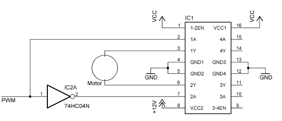
Schaltplan einer Motortreiber-Schaltung
IC1, 1-2EN, VCC1, 16, 15, 1A, 4A, 3, 1Y, 4Y, 4, GND1, GND3, 13, 12, 5, GND, GND2, GND4, 6, 2Y, GND3, 11, 3Y, 7, 2A, 10, 3A, 8, +12V, 9, VCC2, 3-4EN, IC2A, 74HC04N, 1, 2, PWM, Motor
in „Lüftersteuerung via Microcontroller“ · Mikrocontroller und Digitale Elektronik · · Schaltpläne
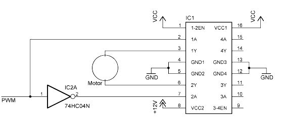
-
Datei
L293D.h
/* * L293D.h * * Created: 19.11.2016 17:26:10 * Author: Kde-PC */ #ifndef L293D_H_ #define L293D_H_ extern void MOTOR_PWM (uint16_t A, uint16_t B); #endif /* L293D_H_ */
in „Externe .c bringt nur theater“ · Mikrocontroller und Digitale Elektronik ·
-
Datei
L293D.c
/* * L293D.c * * Created: 19.11.2016 17:25:46 * Author: Kde-PC */ #include <avr/io.h> #include <avr/interrupt.h> #include "L293D.h" void MOTOR_PWM (uint16_t A, uint16_t B) { OCR1A = A; OCR1B = B; }
in „Externe .c bringt nur theater“ · Mikrocontroller und Digitale Elektronik ·
-
Datei
main.c
TEST_JUMPER PIND5 #define WATCHDOG_JUMPER PIND6 #define DOOR_OPEN PIND6 #define DOOR_CLOSED PINB0 #define L293_ENABLE PC5 #define L293_1A PC4 #define L293_2A PC3 #define LDR_VCC PC2 #define DOOR_TURNOFF_TIME 150 // * 0.1s #include <avr/io.h> #include <avr/interrupt.h> #include <util/delay.h> #include <avr/sleep.h
in „Variablen werden nach aufwachen aus Power Save nicht mehr verändert“ · Mikrocontroller und Digitale Elektronik ·
-
PDF
Relaisansteuerung.sch__1_.pdf
* 9 GND 4 GND1 GND3 13 74HC595N 5 GND2 GND4 12 GND 6 11 GND 2Y 3Y 7 2A 3A 10 8 VCC2 3-4EN 9 +12V L293D 5 IC7 + 1 16 1-2EN VCC1 C7 2 15 1A 4A 100nF 3 1Y 4Y 14 GND 4 GND1 GND3 13 5 12 GND2 GND4 GND 6 2Y 3Y 11 GND 14 SER QA 15 7 2A 3A 10 1 11 QB 2 8 9 10 SCK QC 3 VCC2 3-4EN SCL QD 4 +12V +5V QE L293D 12
-
 Bild
Bild
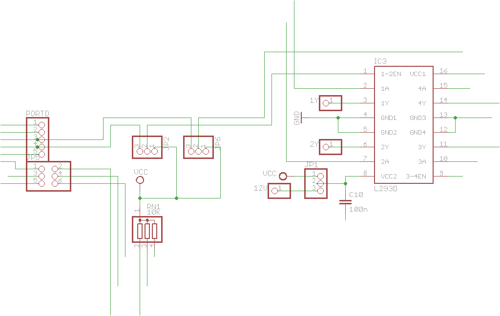
Schaltplan eines L293D Motortreibers
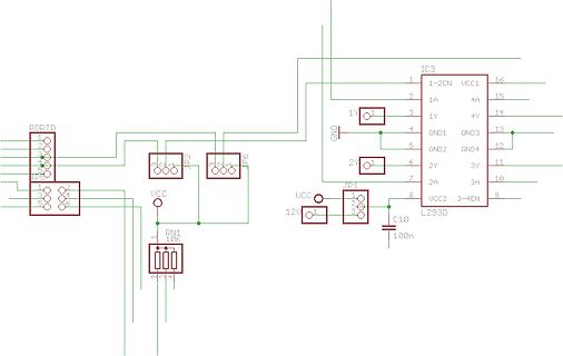
3Y, 2A, 3A, 10, 9, 3-4EN, VCC2, 8, 7, 2Y, 6, 5, GND2, 4, 3, 1Y, 2, 1A, 1, 16, 15, 14, 13, 12, 11, L293D, JP1, UCC, 12V, C10, 100n
in „Schaltplan und Board so OK?“ · Platinen · · Schaltpläne
-
PDF
L297AN.PDF
interface. 1/18 AN470/0392 APPLICATION NOTE Forbipolarmotorswithwindingcurrentsupto2Athe THE L298N AND L293E L297should be used with the L298N ; for winding Sincethe L297 is normally used with an L298Nor currents up to 1Athe L293E is recommended (the L293E bridgedriver a briefreview of these devices L293will
in „µC_Steuerung“ · Mikrocontroller und Digitale Elektronik ·
-
PDF
L297_Application_Note.pdf
interface. 1/18 AN470/0392 APPLICATION NOTE Forbipolarmotorswithwindingcurrentsupto2Athe THE L298N AND L293E L297should be used with the L298N ; for winding Sincethe L297 is normally used with an L298Nor currents up to 1Athe L293E is recommended (the L293E bridgedriver a briefreview of these devices L293will
in „L297: Stromregelung schaltet an, nicht aus“ · Mikrocontroller und Digitale Elektronik ·
-
Datei
PWM023.bas
Interrupts Motor1_w1a Alias Portb.1 'Motorwicklung 1 Ende "a" der ersten Spule. PortB.1 geht zum L293 1A Motor1_w1b Alias Portb.2 'Motorwicklung 1 Ende "b" der ersten Spule. PortB.2 geht zum L293 2A Motor1_w2a Alias Portb.3 'Motorwicklung 2 Ende "a" der zweiten Spule. PortB.3 geht zum L293 3A Motor1
in „Mikroschrittmotor mit L293 oder PBM3960 + PBL3771: Wie programmieren?“ · Mikrocontroller und Digitale Elektronik ·
-
PDF
l293_driver_board.pdf
l293_driver_board.pdf
in „L293 zieht Strom ueber USB - normal?“ · Mikrocontroller und Digitale Elektronik ·
-
PDF
IE3_5_1_Application_Notes_IC_L297.pdf
density is one of the key features of the technology so the L297 die is very compact. THE L298N AND L293E Since the L297 is normally used with an L298N or L293E bridge driver a brief review of these devices will make the rest of this note easier to follow. The L298N and L293E contain two bridge driver
in „Phase Chopping“ · Mikrocontroller und Digitale Elektronik ·
-
Datei
ATmega8515.asm
rirechts ; ja -> richtung rechts stellen sbi PORTB, dir ; Pin 2 (Bit3,PortD) = HIGH -> Linkslauf siehe L293D DS ldi wr0, 0x62 ; DS S91 T47 und DS L293 S9 Fig/Tab5 - Turnleft = LOW out TCCR0, wr0 ; COM01 = 1 COM00 = 0 ; -> OCR0 - BOTTOM - CCR0 = LOW -> OCR0 steigend -> länger LOW -> schneller rjmp richteinstend rirechts: cbi PORTB, dir ; Pin 2 = LOW -> Rechtslauf DS von L293D ldi wr0, 0x72 ; DS S91 T47 und DS L293 S9 Fig/Tab5 - Turnright = HIGH out TCCR0, wr0 ; COM01 = 1 COM00 = 1 ; -> OCR0 - Bottom - CCR0 = HIGH -> OCR0 steigend -> länger HIGH -> schneller richteinstend
in „mC arbeitet nicht“ · Mikrocontroller und Digitale Elektronik ·
-
Datei
Drehzahl-ST.asm
rirechts ; ja -> richtung rechts stellen sbi PORTD, dir ; Pin 2 (Bit3,PortD) = HIGH -> Linkslauf siehe L293D DS ldi wr0, 0x62 ; DS S91 T47 und DS L293 S9 Fig/Tab5 - Turnleft = LOW out TCCR0, wr0 ; COM01 = 1 COM00 = 0 ; -> OCR2 - BOTTOM - CCR0 = LOW -> OCR2 steigend -> länger LOW -> schneller rjmp richteinstend rirechts: cbi PORTD, dir ; Pin 2 = LOW -> Rechtslauf DS von L293D ldi wr0, 0x72 ; DS S91 T47 und DS L293 S9 Fig/Tab5 - Turnright = HIGH out TCCR0, wr0 ; COM01 = 1 COM00 = 1 ; -> OCR2 - Bottom - CCR0 = HIGH -> OCR2 steigend -> länger HIGH -> schneller richteinstend
in „Fehler im ASM-Code zur Motorsteuerung“ · Mikrocontroller und Digitale Elektronik ·
-
Datei
Drehzahl-ST.asm
rirechts ; ja -> richtung rechts stellen sbi PORTD, dir ; Pin 2 (Bit3,PortD) = HIGH -> Linkslauf siehe L293D DS ldi wr0, 0x75 ; DS S91 T47 und DS L293 S9 Fig/Tab5 - Turnleft = HIGH out TCCR2, wr0 ; COM01 = 1 COM00 = 0 ; -> OCR2 - BOTTOM - CCR0 = HIGH -> OCR2 steigend -> länger LOW -> schneller rjmp richteinstend rirechts: cbi PORTD, dir ; Pin 2 = LOW -> Rechtslauf DS von L293D ldi wr0, 0x65 ; DS S91 T47 und DS L293 S9 Fig/Tab5 - Turnright = LOW out TCCR2, wr0 ; COM01 = 1 COM00 = 1 ; -> OCR2 - Bottom - CCR0 = LOW -> OCR2 steigend -> länger HIGH -> schneller richteinstend:
in „Motorentreiber L293D“ · Analoge Elektronik und Schaltungstechnik ·
-
PDF
Thermodruck.pdf
4:2 V bis 8.5 V. 1.2.2 Der Stepper Pro Pixel sind zwei Schritte notig. Ich steuere ihn mit einem L293D an, damit scha▯t der Stepper an einer Versorgung mit 8 V ca. 500 Steps/s (2 ms Delay). Der Spulenwi- derstand liegt bei ca. 15 , deshalb sollte der L293 zwische drin uber seine Enable{Pins abgeschaltet
in „Thermodrucker mbl1314a“ · Mikrocontroller und Digitale Elektronik ·
-
PDF
rnvn2dualmotor.pdf
Steuerung ist sehr einfach, nahezu identisch mit der Ansteuerung der beliebten Motorchips L298 oder L293D. Die Geschwindigkeit ist über einem PWM-Port, der bis zu 20 Khz liefern darf, regelbar. Weitere 2 Eingänge bestimmen die Drehrichtung oder Motorbremsung. Der Anschluss erfolgt über 10 poligen Wannenstecker
in „Ansteuerung von Motor-Treiber mit PWM“ · Mikrocontroller und Digitale Elektronik ·
-
PDF
MITSUBISHI_CV-0MW7B51.pdf
TR 2SD2375OP R062,066,etc. 103L292O9 R-CHIP 2.2k Q001,004,etc. 260M061O6 TR-CHIP 2SA1037AK R506 103L293O0 R-CHIP 2.7k Q905 260L047O1 TR-CHIP 2SA1369 Q002,003,005 260M061O5 TR-CHIP 2SC2412K R006,511 103L293O1 R-CHIP 3.3k R508 103L293O2 R-CHIP 3.9k Q954 260L100O1 TR-CHIP 2SD1760 R003,013,etc. 103L293O3
in „Verstärker reparieren“ · Analoge Elektronik und Schaltungstechnik ·
-
Datei
rbook_src.txt
3 pin3: connected to vcc aka grün aka 2 pin4: connected to gnd (via pulldown) aka gelb aka 1 */ //L293B to turn the DC-motor clockwise/counter-clockwise const byte DCmotor_OutPin1 = 9; //L293B Pin2 const byte DCmotor_OutPin2 = 10; //L293B Pin7m //global variables int i=0; const unsigned long wheel_circumfence
in „mc-Roadbook: Tachosignal entstören“ · Mikrocontroller und Digitale Elektronik ·
-
PDF
user-mannual-for-esp-12e-motor-shield.pdf
NodeMCU Lua module. This shield board is driven by the special excent large power full-bridge chip L293DD from the famous Stmicroelectronics company, which can directly drive 2-channels DC motors or one-channel stepper motor. The driven current can be arrived at 1.2A. This board is generated with national
in „Motorshield 12e / ESP8266“ · Mikrocontroller und Digitale Elektronik ·
-
PDF
Schrittmotor.pdf
Drehscheibe mit den Permanentmotoren im Außenring. Der geeignete Leistungstreiber hierfür ist der L293D. Es ist ein Superchip, der für viele Anwendungen eingesetzt werden kann. Seine Ausgänge folgen dem angelegten Einganspotenzial. Liegt hier ein Lowsignal, so ist der Ausgang als Masse anzusehen, liegt
in „schrittmotor Steuerung“ · Platinen ·
-
PDF
Anleitung.pdf
K5 C5 K13 K15 1 C14 R C9 K2 6 1 2 IC5 C2 C Q Q 2 K9 P C10 K K 3 2 X I 1 90S8535-Board für K16 M C L293D Roboter 2 IC4 Version: 1.1 1 C4 C12 2 4 3 5 6 7 8 9 06.04.02 M1 M2 L DLD L DLD L L L L K10 RN3 Seite 4 von 18 Kai Sachsenheimer 27.04.02 Reihenfolge der Bestückung entsprechend der Tabelle von oben
in „AVR_Ctrl mit BasCom programmieren“ · Mikrocontroller und Digitale Elektronik ·
-
 Bild
Bild
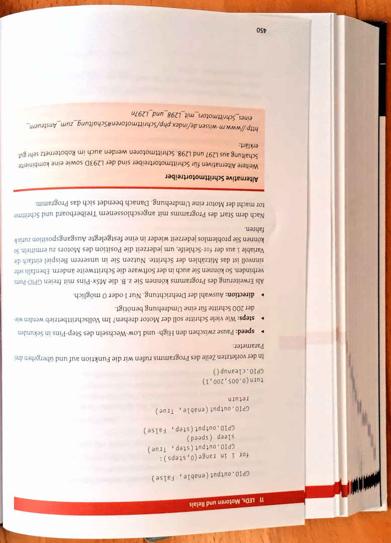
Abfotografierter Text über Schrittmotoren und Python-Code
index.php/Schrittmotoren_mit_L297_und_L297n Weitere Alternativen für Schrittmotortreiber sind der L293D sowie eine kombinierte Schaltung aus L297 und L298. Danach beendet sich das Programm. Nach dem Start des Programms mit angeschlossenem Treiberboard und Schrittmo- tor kann Sie jederzeit wieder in eine
in „Tipps zu: 600+ Schrittmotoren ansteuern“ · Mikrocontroller und Digitale Elektronik · · Fotos
-
Datei
ICs.txt
Alles DIL Bausteine / 20.08.2021 5St ST24C16 neu 1St L293E 1St. UA741 2St. SG351G 1St TC4053 1St. PALCE16V8 neu 3St. Dallas DS1307 DIL 3St. 74LS244 DIL 1St. 74LS32 3St. 74LS14N 1St. 74LS02N 1St. 74LS74N 1St. 74LS17N 2St. 74LS123 2St. 74LS122 1St. 74LS92N 2St
-
PDF
Auflistung_Bauteile.pdf
current controller L6208N 1 DMOS driver for bipolar stepper motor L297D013TR 3 STEPPER MOTOR CONTROLLER L293E 3 PUSH-PULL FOUR CHANNEL DRIVERS DRV8811PWP 5 DRV8811 Stepper Motor Controller IC 2ED020i12-Fi 5 Half Bridge Driver L297/1 3 STEPPER MOTOR CONTROLLER L298HN 3 DUAL FULL-BRIDGE DRIVER L298P013TR 3 DUAL
in „[V] diverse Bauteile (Fets, BMS-ICs, Motor-Treiber“ · Markt ·
-
PDF
Schematic_Smart_Greenhouse_20200410231436.pdf
P4 6 GND P0 25 5 P13 P2 24 4 SD2 P15 23 3 SD3 SD1 22 C RND 205-00287 Motor Driver 2 CMD SD0 21 C L293D 1 1 20 2 1 ENABLE1 VSS 16 Vin (5V) CLK 2 INPUT1 INPUT4 15 USB 3 OUTPUT1 OUTPUT4 14 RND 205-00287 4 GND GND 13 1 5 GND GND 12 2 6 OUTPUT2 OUTPUT3 11 7 INPUT2 INPUT3 10 8 9 VS ENABLE2 D D Power Supply
in „ESP 32 Schaltung“ · Mikrocontroller und Digitale Elektronik ·
-
PDF
Schematic_Smart_Greenhouse_Smart_Greenhouse_20200410163337.pdf
ESP 15 3 SD3 SD1 22 GND Sensor NC GND 2 CMD SD0 21 1 Vin (5V) CLK 20 +5V USB Motor Driver ESP 12 L293D ESP 3.3V W ESP 13 1 ENABLE1 VSS 16 4 D 2 2 2 INPUT1 INPUT4 15 ESP 27 2 D V 2 3 OUTPUT1 OUTPUT4 14 2 2 2 GND 4 GND GND 13 GND 1 1 5 GND GND 12 p TITLE: a 1 6 OUTPUT2 OUTPUT3 11 1 m Smart Greenhouse
in „ESP 32 Schaltung“ · Mikrocontroller und Digitale Elektronik ·
-
Datei
Stepper.h
can be reduced from 4 to 2. A slightly modified circuit around a Darlington transistor array or an L293 H-bridge connects to only 2 microcontroler pins, inverts the signals received, and delivers the 4 (2 plus 2 inverted ones) output signals required for driving a stepper motor. The sequence of control
in „Frage zu Arduino Library?“ · Mikrocontroller und Digitale Elektronik ·
-
Datei
main_mit_c.c
include <util/delay.h> #include <avr/interrupt.h> #include "HC_SR_04.h" #include "USART.h" #include "L293D.h" /****************************************************************************************************************************/ /***************************************************** Globale Variablen
in „Externe .c bringt nur theater“ · Mikrocontroller und Digitale Elektronik ·
-
PDF
picaxe_manual3.pdf
control two motors. A convenient and cheap approach would be to use a motor driver IC such as the L293D. This IC will allow control of two dc motors, using four data lines from the microcontroller. Naturally, if only one motor is to be controlled then only two output lines are used. V2+ 1 5V 5V 16 Pin
in „8 leds an einen prot eines mc?“ · Mikrocontroller und Digitale Elektronik ·
-
Datei
StepperMotors.h
AVR-GCC 3.3 */ /* Hardware: Bipolarer Schrittmotor */ /* Ansteuerung des Schrittmotrs über den */ /* L293D: push-pull 4 Kanal Treiber mit Dioden */ /************************************************************************/ #ifndef _SCHRITTMOTOR_H_ #define _SCHRITTMOTOR_H_ #if (__GNUC__ * 100 + __GNUC_MINOR
in „avrgcc c++ gloables objekt?“ · Mikrocontroller und Digitale Elektronik ·
-
PDF
schaltplan-final.pdf
TOSC1) 28 PC6 2 D D D D VS 8 VCC 3 CTS 16 PD2 (INT0) PC5 (TDI) 27 PC5 3 N N N N 16 RADR 17 26 PC4 L293D G G G G VSS 4 PWM1B 18 PD3 (INT1) PC4 (TDO) 25 PC3 4 5 PWM1A 19 PD4 (OC1B) PC3 (TMS) 24 PC2 5 1 1 5 4 6 KLAPPE 20 PD5 (OC1A) PC2 (TCK) 23 PC1 6 7 PWM2 PD6 (ICP1) PC1 (SDA) PC0 7 POW1 J3 VCC 8 21 PD7
in „LCD DEM20485 in gerade Zeile springen (c't-Bot)“ · Mikrocontroller und Digitale Elektronik ·
-
Datei
Stepper.cpp
can be reduced from 4 to 2. A slightly modified circuit around a Darlington transistor array or an L293 H-bridge connects to only 2 microcontroler pins, inverts the signals received, and delivers the 4 (2 plus 2 inverted ones) output signals required for driving a stepper motor. The sequence of control
in „Frage zu Arduino Library?“ · Mikrocontroller und Digitale Elektronik ·
-
PDF
L6506.pdf
tosenseand controlthe currentin steppingmotors and similar devices.Whenusedin conjunctionwith the L293, L298, L7150, L6114/L6115,the chip set forms a constantcurrent drive for an inductiveload andperformsalltheinterfacefunctionfromthecon- trollogic thru the powerstage. DIP18 SO20 Two or more devices
in „Frage zum L6506“ · Mikrocontroller und Digitale Elektronik ·
-
Datei
w48_handy_test.bas
' Bit 1 Ausgang Klingel EIN/AUS (spÀter A-Leitung) ' Bit 2 Ausgang Klingel_b Enable (Ansteuerung L293 direkt) ' Bit 3 Ausgang Handy_power ' Bit 4 Ausgang Handy_on (Einschaltkontakt) ' Bit 5 Ausgang Waehlton EIN/AUS (spÀter A-Leitung) ' Bit 6 Ausgang Waehlton_b (Ansteuerung Hörer direkt) Gabel Alias
in „Handy mit Wählscheibe“ · Mikrocontroller und Digitale Elektronik ·
-
Datei
Infrarot_am_COM_Mit_TSOP_17xx.htm
content="Hier finden sie alles zum Thema Elektronik am PC, LPT, Elektronik Forum, RS232, ULN2803, L293, Schrittmotor am PC, ComPort, QBasic, 4094, 4021, TSOP, TLC549, AD Wandler am Com, Ausganserweiterung am COM Port, Eingangserweiterung, Motorsteuerung am PC, Minimodellbau, Modellbau, serielle Schnittstelle
in „TSOP-Schaltung und programm“ · Mikrocontroller und Digitale Elektronik ·
-
PDF
L297_2.pdf
half step, normal and wawe drive modes and on-chip PWM chopper circuits permit switch- the L298N or L293E, or with discrete transistors mode control of the current in the windings. A and darlingtons. ABSOLUTE MAXIMUM RATINGS Symbol Parameter Value Unit V Supply voltage 10 V s Vi Input signals 7 V P tot
in „Schrittmotor+Schaltung“ · Mikrocontroller und Digitale Elektronik ·
-
PDF
flipdot.pdf
R547 R549 R551 R553 R555 R557 R559 R561 R563 R565 R567 R569 R571 L286 L287 L288 L289 L290 L291 L292 L293 L294 L295 L296 L297 L298 L299 L300 L301 L302 L303 L304 L305 L306 L307 L308 L309 L310 L311 L312 L313 ROW_10A R572 R574 R576 R578 R580 R582 R584 R586 R588 R590 R592 R594 R596 R598 R600 R602 R604 R606
in „Flipdot Matrix - FP2800A“ · Mikrocontroller und Digitale Elektronik ·
-
PDF
flipdot.pdf
D546 D548 D550 D552 D554 D556 D558 D560 L281 L282 L283 L284 L285 L286 L287 L288 L289 L290 L291 L292 L293 L294 L295 L296 L297 L298 L299 L300 L301 L302 L303 L304 L305 L306 L307 L308 ROW_10A D561 D563 D565 D567 D569 D571 D573 D575 D577 D579 D581 D583 D585 D587 D589 D591 D593 D595 D597 D599 D601 D603 D605
in „Flipdot Matrix - FP2800A“ · Mikrocontroller und Digitale Elektronik ·
-
PDF
app6219-1.pdf
bridge drawnfrom the power supply is very low. output, is another concern. The design of the L298N, L293 and L6202 all include circuitry spe- cifically to prevent this phenomena. The user should not mistake the reverse recovery current Avoid Destroying the Driver of the diodes or the parasitic structuresin
in „Motoransteuerung (24V, 4A) mit Mikrocontroller“ · Mikrocontroller und Digitale Elektronik ·
-
PDF
Vergleichsliste.pdf
STR3135 ECG1744 AN6291 AN6291K ECG1745 M54459P ECG1746 TD6306 ECG1747 AN5318 ECG1748 STK6962 ECG1749 L293 L293B ECG1750 L295 ECG1751 X0137CE T2508 ECG1752 TDA2546A ECG1753 MC34060P ECG1754 TDA3651 TDA3654 TDA3652 ECG1755 SL490B ECG1756 T.B.A. ECG1757 ML924 ECG1758 UPD1986C ECG1759 UPD1987C ECG1760 SAF1039
in „ECG45 was ist das?“ · Analoge Elektronik und Schaltungstechnik ·