-
PDF
LT3092fb.pdf
SOT-223 –40°C to 125°C LT3092IST#PBF LT3092IST#TRPBF 3092 3-Lead Plastic SOT-223 –40°C to 125°C LT3092MPST#PBF LT3092MPST#TRPBF 3092MP 3-Lead Plastic SOT-223 –55°C to 125°C LT3092ETS8#PBF LT3092ETS8#TRPBF LTFJW 8-Lead Plastic SOT
in „Konstantstromquelle LT3092 - Widerstandswahl“ · Analoge Elektronik und Schaltungstechnik ·
-
Bild
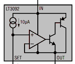
Schaltplan des LT3092 ICs
LT3092 IN 10µA SET OUT
in „Beurteilung erster PCB-Entwurf“ · Platinen · · Schaltpläne
-
Bild
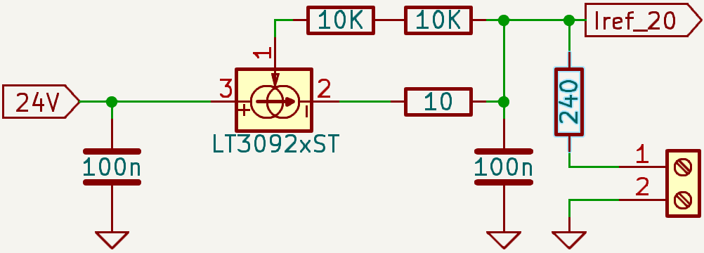
Schaltplan eines Stromquellen-Schaltkreises mit LT3092xST
24V 100n LT3092xST 1 2 3 10K 10K Iref_20 240 10 100n 1 2
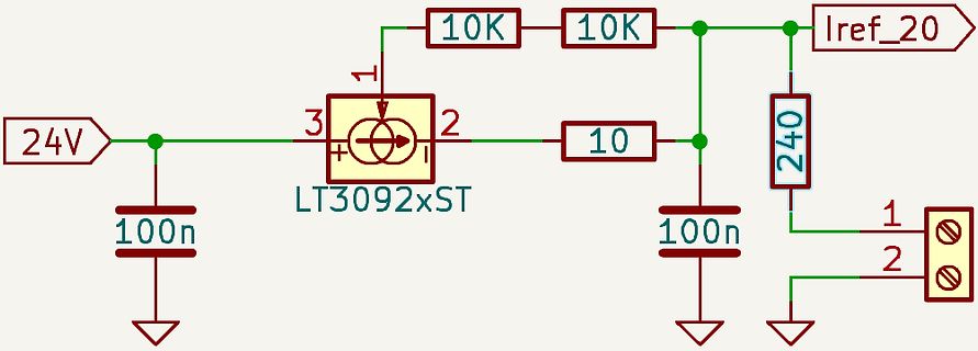
in „Präzise Referenzstromquelle 20mA 0,1%“ · Analoge Elektronik und Schaltungstechnik · · Schaltpläne
-
PDF
LTJournal-V24N2-02-df-BenchSupply-Szolusha.pdf
CURRENT PNP LT3081 ILIM LIMITED VOUT 100k ILIM 4.99k ADJUST VOUT I IN LIM SET 50µA 200Ω SET VIN + LT3092 2.4mA – 47.5k OUT 10mΩ LT3081 VOUT Figure 1. Block diagram of the mixed- CURRENT SOURCE ADJUST mode DC bench supply. The central INSERTS 2.4mA INTO SET PIN OF LT3081 TO components are the parallel
in „Dimensionierung meines Labornetzteil“ · Analoge Elektronik und Schaltungstechnik ·
-
PDF
LTJournal-V24N2-02-df-BenchSupply-Szolusha.pdf
CURRENT PNP LT3081 ILIM LIMITED VOUT 100k ILIM 4.99k ADJUST VOUT I IN LIM SET 50µA 200Ω SET VIN + LT3092 2.4mA – 47.5k OUT 10mΩ LT3081 VOUT Figure 1. Block diagram of the mixed- CURRENT SOURCE ADJUST mode DC bench supply. The central INSERTS 2.4mA INTO SET PIN OF LT3081 TO components are the parallel
in „Suche Stereo Multiturn Potentiometer“ · Analoge Elektronik und Schaltungstechnik ·
-
Bild
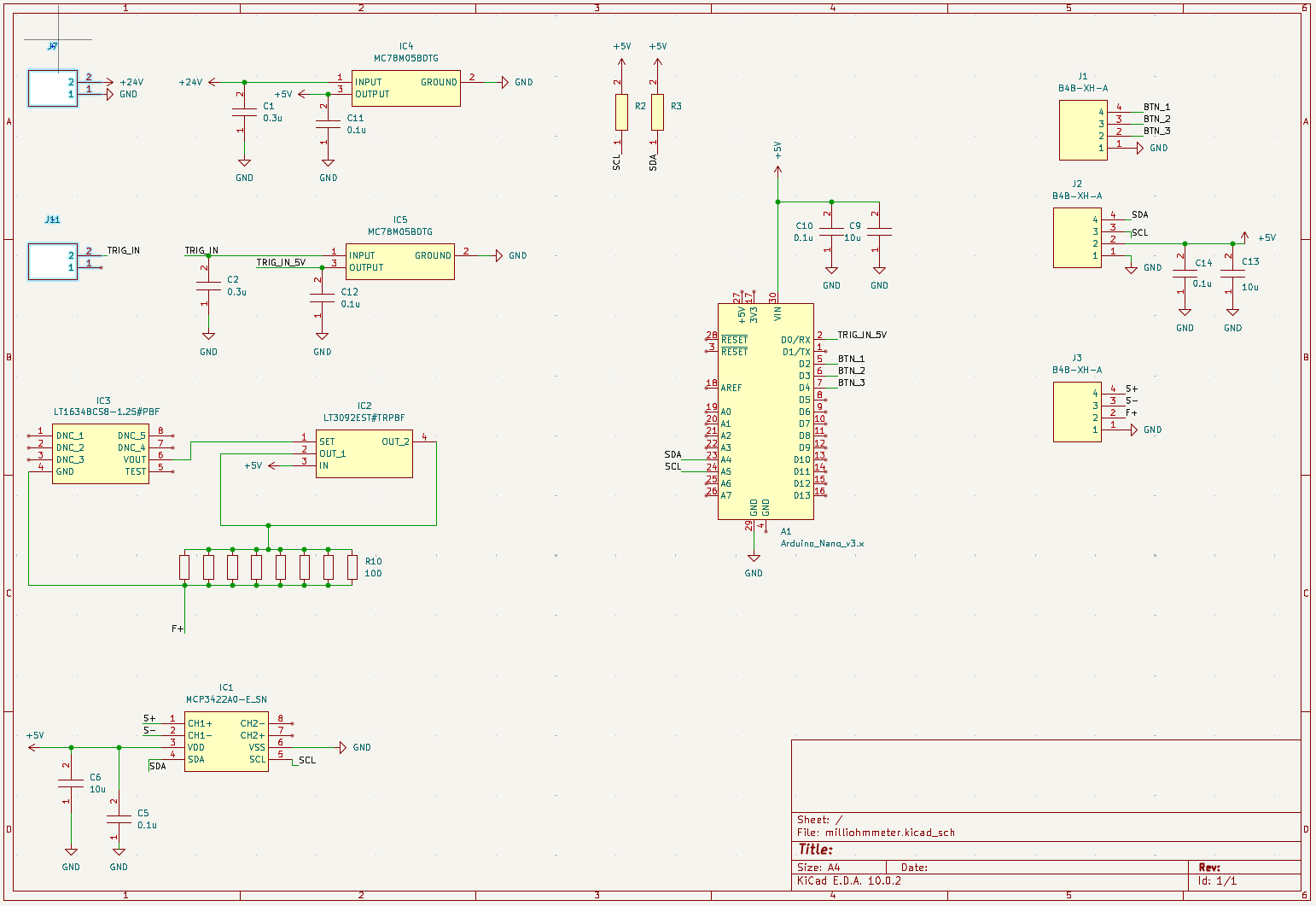
Schaltplan eines Milliohmmeter-Projekts
IC4 MC78M05BTG, IC3 LT3092EST#TRPBF, IC1 Arduino_Nano_v3.x, J1 B4B-XH-A, J2 B4B-XH-A, J3 B4B-XH-A, C1 0.3u, C2 0.3u, C5 0.1u, C6 10u, C9 10u, C10 0.1u, C12 0.1u, C13 10u, R2, R3, R10 100, Sheet: milliohmmeter.klcad_sch, Title
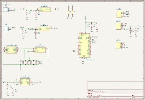
in „Beurteilung erster PCB-Entwurf“ · Platinen · · Schaltpläne
-
PDF
AoE3_chapter9.pdf
. Happily, with regulators like the LM317, rent (versus voltage across it), but the LT3092 kicks in at a this circuit (Figure 9.34B) becomes more attractive: only lower voltage. 1.25V is used to set the current; and the regulator’s op- Note that the current sources in Figures 9.34B and D
in „Labornetzgerät - Fragen zum Schaltplan“ · Analoge Elektronik und Schaltungstechnik ·