-
Datei
Adafruit_ST7735.h
#define ST7735_PTLON 0x12 #define ST7735_NORON 0x13 #define ST7735_INVOFF 0x20 #define ST7735_INVON 0x21 #define ST7735_DISPOFF 0x28 #define ST7735_DISPON 0x29 #define ST7735_CASET 0x2A #define ST7735_RASET 0x2B #define ST7735_RAMWR 0x2C #define ST7735_RAMRD 0x2E #define ST7735_PTLAR 0x30 #define ST7735_COLMOD 0x3A #define ST7735_MADCTL 0x36 #define ST7735_FRMCTR1 0xB1 #define ST7735_FRMCTR2 0xB2 #define ST7735_FRMCTR3 0xB3
in „Fehlermeldung Arduino C++“ · Mikrocontroller und Digitale Elektronik ·
-
Datei
Adafruit_ST7735.cpp
use SPI pins // specific to each board type (e.g. 11,13 for Uno, 51,52 for Mega, etc.) Adafruit_ST7735::Adafruit_ST7735(uint8_t cs, uint8_t rs, uint8_t rst) : Adafruit_GFX(ST7735_TFTWIDTH, ST7735_TFTHEIGHT) { _cs = cs; _rs = rs; _rst = rst; hwSPI = true; _sid = _sclk = 0; } inline void Adafruit_ST7735
in „Fehlermeldung Arduino C++“ · Mikrocontroller und Digitale Elektronik ·
-
Datei
lcd-routines.asm
;ST7735 TFT LCD Routines .equ ST7735_NOP = 0x00 .equ ST7735_SWRESET = 0x01 .equ ST7735_RDDID = 0x04 .equ ST7735_RDDST = 0x09 .equ ST7735_SLPIN = 0x10 .equ ST7735_SLPOUT = 0x11 .equ ST7735_PTLON = 0x12 .equ ST7735_NORON = 0x13 .equ ST7735_INVOFF = 0x20 .equ ST7735_INVON = 0x21 .equ ST7735_GAMSET = 0x26 .equ ST7735_DISPOFF = 0x28 .equ ST7735_DISPON = 0x29 .equ ST7735_CASET = 0x2A .equ ST7735_RASET = 0x2B .equ
in „Problem mit TFT (ST7735S basierent)“ · Mikrocontroller und Digitale Elektronik ·
-
Datei
Shruthi2_102.txt
20+23, 21+22 #define TFT_RST 9 // RST can use any pin #define RGB(r,g,b) (b<<11|g<<6|r) #define ST7735_BLACK 0x0000 #define ST7735_GRAY 0x8410 #define ST7735_WHITE 0xFFFF #define ST7735_RED 0xF800 #define ST7735_ORANGE 0xFA60 #define ST7735_YELLOW 0xFFE0 #define ST7735_LIME 0x07FF #define ST7735_GREEN 0x07E0 #define ST7735_CYAN 0x07FF #define ST7735_AQUA 0x04FF #define ST7735_BLUE 0x001F #define ST7735_MAGENTA 0xF81F #define ST7735_PINK 0xF8FF #define Menu_Osc 0 // Menu pages #define Menu_AmpEnv 1 #define Menu_FilterEnv
in „Teensy Synth "Shruthi 2"“ · Mikrocontroller und Digitale Elektronik ·
-
Datei
st7735_soft_spi_bluepill_02.ino
ST7735_INVOFF 0x20 #define ST7735_INVON 0x21 #define ST7735_DISPOFF 0x28 #define ST7735_DISPON 0x29 #define ST7735_CASET 0x2A #define ST7735_RASET 0x2B #define ST7735_RAMWR 0x2C #define ST7735_RAMRD 0x2E #define ST7735_PTLAR 0x30 #define ST7735_COLMOD 0x3A #define ST7735_MADCTL 0x36 #define ST7735_FRMCTR1 0xB1 #define ST7735_FRMCTR2 0xB2 #define ST7735_FRMCTR3 0xB3 #define ST7735_INVCTR 0xB4 #define ST7735_DISSET5
in „Arduino IDE mit STM32 Core Themen, BluePill, SPI 2“ · Mikrocontroller und Digitale Elektronik ·
-
Datei
st7735_hard_spi_bluepill_02.ino
ST7735_INVOFF 0x20 #define ST7735_INVON 0x21 #define ST7735_DISPOFF 0x28 #define ST7735_DISPON 0x29 #define ST7735_CASET 0x2A #define ST7735_RASET 0x2B #define ST7735_RAMWR 0x2C #define ST7735_RAMRD 0x2E #define ST7735_PTLAR 0x30 #define ST7735_COLMOD 0x3A #define ST7735_MADCTL 0x36 #define ST7735_FRMCTR1 0xB1 #define ST7735_FRMCTR2 0xB2 #define ST7735_FRMCTR3 0xB3 #define ST7735_INVCTR 0xB4 #define ST7735_DISSET5
in „Arduino IDE mit STM32 Core Themen, BluePill, SPI 2“ · Mikrocontroller und Digitale Elektronik ·
-
Datei
test_tft.c
small & Medium low 0x2A, ST7735_PWCTR5 , 2 , // 11: Power control, 2 args, no delay: 0x8A, 0xEE, ST7735_VMCTR1 , 1 , // 12: Power control, 1 arg, no delay: 0x0E, ST7735_INVOFF , 0 , // 13: Don't invert display, no args, no delay ST7735_MADCTL , 1 , // 14: Memory access control (directions), 1 arg: 0xC8, // row addr/col addr, bottom to top refresh ST7735_COLMOD , 1 , // 15: set color mode, 1 arg, no delay: 0x05, // 16-bit color ST7735
in „Problem mit TFT (ST7735S basierent)“ · Mikrocontroller und Digitale Elektronik ·
-
PDF
ST7735S.pdf
............................................................. 158 V 1.1 Page 9 of 201 2011-11-21 ST7735S 1 GENERAL DESCRIPTION The ST7735S is a single-chip controller/driver for 262K-color, graphic type TFT-LCD. It consists of 396 source line and 162 gate line driving circuits. This chip is capable of
in „[STM32/HAL] Treiber für ST7735 160 x 80 TFT“ · Projekte & Code ·
-
PDF
ST7735_128x160_SPI_Display.pdf
ST ST7735 262K Color Single-Chip TFT Controller/Driver 1 Introduction The ST7735 is a single-chip controller/driver for 262K-color, graphic type TFT-LCD. It consists of 396 source line and 162 gate line driving
in „ST7735 an MCU“ · Mikrocontroller und Digitale Elektronik ·
-
Datei
User_Setup.h
wrong, mirror images, or tray pixels at the edges. // Comment out ALL BUT ONE of these options for a ST7735 display driver, save this // this User_Setup file, then rebuild and upload the sketch to the board again: // #define ST7735_INITB // #define ST7735_GREENTAB // #define ST7735_GREENTAB2 // #define ST7735_GREENTAB3 // #define ST7735_GREENTAB128 // For 128 x 128 display // #define ST7735_GREENTAB160x80 // For 160 x 80 display (BGR, inverted, 26 offset) // #define ST7735_REDTAB // #define ST7735_BLACKTAB // #define ST7735_REDTAB160x80
in „Powerpins am ESP32-DevKitC, WDT_RTC_RESET“ · Mikrocontroller und Digitale Elektronik ·
-
Datei
_4.0_User_Setup.h
wrong, mirror images, or tray pixels at the edges. // Comment out ALL BUT ONE of these options for a ST7735 display driver, save this // this User_Setup file, then rebuild and upload the sketch to the board again: //#define ST7735_INITB //#define ST7735_GREENTAB //#define ST7735_GREENTAB2 //#define ST7735_GREENTAB3 //#define ST7735_GREENTAB128 // For 128 x 128 display //#define ST7735_REDTAB //#define ST7735_BLACKTAB // ################################################################################## // // Section 1. Define
in „Esp32 Display“ · Mikrocontroller und Digitale Elektronik ·
-
PDF
TableClonesEn-2022.pdf
ATMega328, 1.8" SPI TL431, zener diodes (<5V), diode possible +9V, 8pin, update to connector DIP, ST7735, divider resistors, assembly, 1.13к or ext. ≥10-15$ 8MHz 160x128, port PC5, capacitors, chokes, suppressor 1.48m 9-12V RGB r.encoder inductors voltmeter, (TVS) frequency 6V8A generator, frequency meter
-
PDF
Clone-Comparison-Chart.pdf
ATMega328, 1.8" SPI TL431, zener diodes (<5V), diode possible +9V, 8pin, update to connector DIP, ST7735, divider resistors, assembly, 1.13к or ext. ≥10-15$ 8MHz 160x128, port PC5, capacitors, chokes, suppressor 1.47m 9-12V RGB r.encoder inductors voltmeter, (TVS) frequency 6V8A generator, frequency meter
-
 Bild
Bild
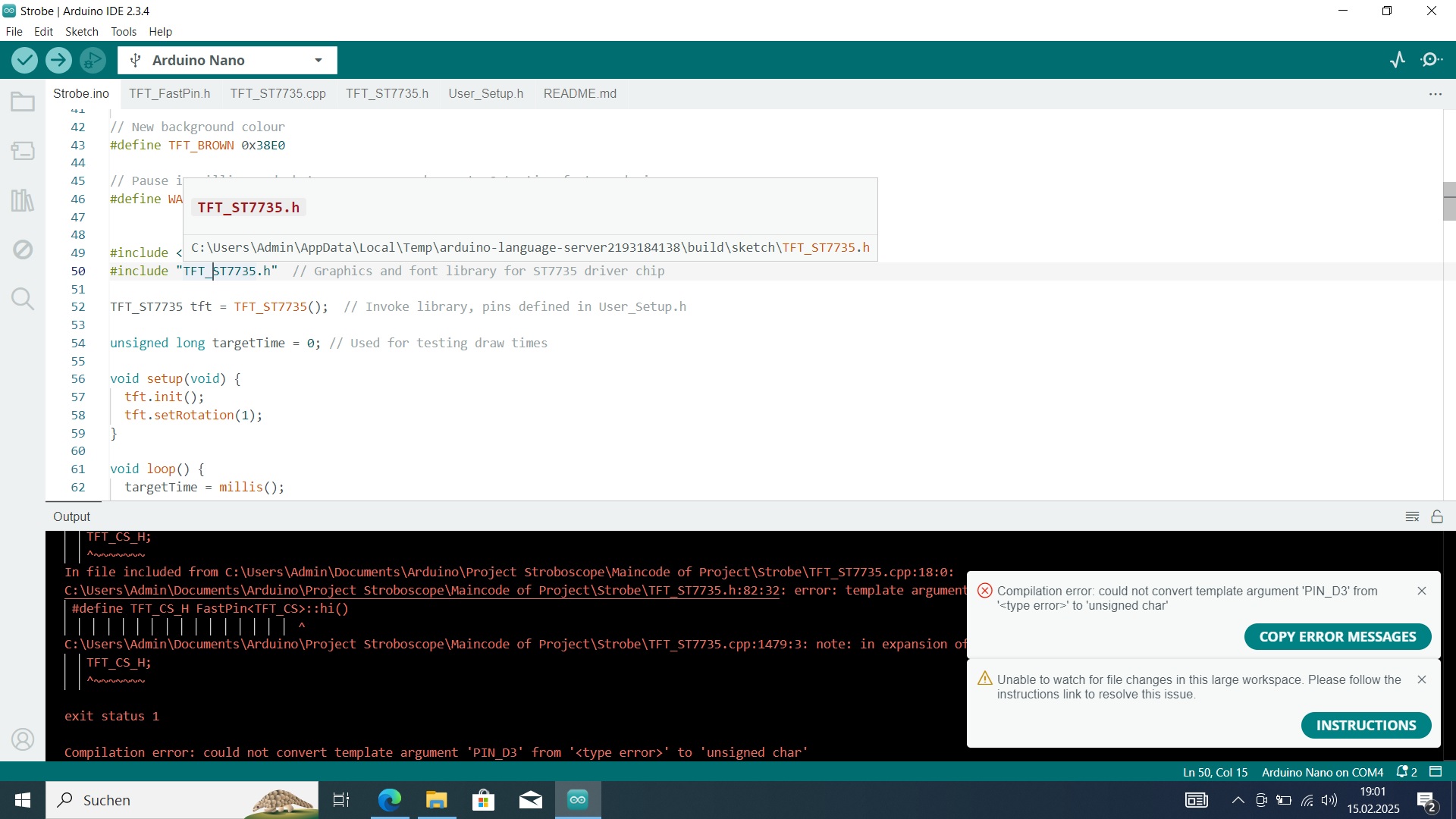
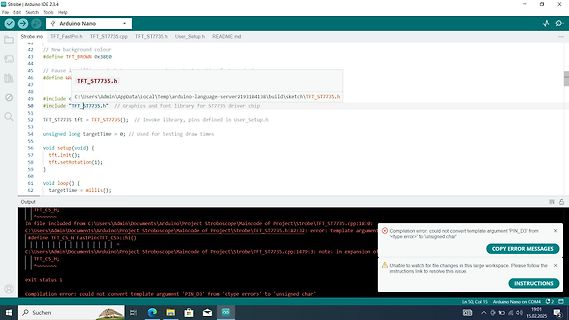
Arduino IDE Fehlermeldung beim Kompilieren
Strobe | Arduino IDE 2.3.4 Strobe.ino TFT_FastPin.cpp TFT_ST7735.cpp TFT_ST7735.h User_Setup.h README.md #include <C:\Users\Admin\AppData\Local\Temp\arduino-language-server-2193184138\build\TFT_ST7735.h> #include "TFT_ST7735.h" void setup() { tft.init(); targetTime
in „Arduino greift nicht auf Libary zu“ · Mikrocontroller und Digitale Elektronik · · Screenshots
-
PDF
picomon_v3.pdf
• 320 * 240 Pixel Hierbei werden folgende Displaycontroller unterstützt: • ILI 9163 • ILI 9340 • ST 7735 / ST 7735R • ST 7789 • S6D02A1 • ILI 9225 Für die Darstellung von Zeichen sind 4 verschiedene Schriftgrößen definiert: • 5x7 Pixel (benötigt zur Darstellung auf dem Display 6x8 Pixel) • 8x8 Pixel
in „PicoMon für CH32V003 oder STM32F0xx“ · Projekte & Code ·
-
PDF
picomon.pdf
• 320 * 240 Pixel Hierbei werden folgende Displaycontroller unterstützt: • ILI 9163 • ILI 9340 • ST 7735 / ST 7735R • ST 7789 • S6D02A1 • ILI 9225 Für die Darstellung von Zeichen sind 4 verschiedene Schriftgrößen definiert: • 5x7 Pixel (benötigt zur Darstellung auf dem Display 6x8 Pixel) • 8x8 Pixel
in „PicoMon für CH32V003 oder STM32F0xx“ · Projekte & Code ·
-
Datei
Laufschrift_04_Test_Fehler_Reset.ino
define TFT_DC 8 #define LED 5 // Kontrollled #define TFT_HGB 3 // Hintergrundbeleuchtung Adafruit_ST7735 tft = Adafruit_ST7735(TFT_CS, TFT_DC, TFT_RST); void setup() { Serial.begin(9600); Serial.setTimeout(200); //Timeout auf 100ms pinMode(VRW, INPUT); pinMode(RKW, INPUT); Serial.print("Initialisiere Display..."); tft.initR(INITR_MINI160x80_PLUGIN); // Init ST7735S mini display Serial.println(" Fertig"); Serial.print("Starte Programm..."); tft.setRotation(1); tft.invertDisplay(false); tft.setTextWrap(false); // Kein Textumbruch beim scrollen Serial.print("A"
in „ATmega328P resettet bei I/O Zugriff“ · Mikrocontroller und Digitale Elektronik ·
-
Datei
error.txt
Os -mcall-prologues -funsigned-char -funsigned-bitfields -fpack-struct -fshort-enums -MD -MP -MT ST7735.o -MF dep/ST7735.o.d -c ST7735.c avr-gcc -mmcu=atmega328 -Wall -I. -Ibitmaps -DF_CPU=8000000UL -DOSC_STARTUP=16384 -gdwarf-2 -std=gnu99 -Os -mcall-prologues -funsigned-char -funsigned-bitfields -fpack-struct -fshort-enums -MD -MP -MT Semi_ST7735.o -MF dep/Semi_ST7735.o.d -c Semi_ST7735.c avr-gcc -mmcu=atmega328 -Wall -I. -Ibitmaps -DF_CPU=8000000UL -DOSC_STARTUP=16384 -gdwarf-2 -std=gnu99 -Os -mcall-prologues -funsigned-char -funsigned-bitfields
-
Datei
error.txt
Os -mcall-prologues -funsigned-char -funsigned-bitfields -fpack-struct -fshort-enums -MD -MP -MT ST7735.o -MF dep/ST7735.o.d -c ST7735.c avr-gcc -mmcu=atmega328 -Wall -I. -Ibitmaps -DF_CPU=8000000UL -DOSC_STARTUP=16384 -gdwarf-2 -std=gnu99 -Os -mcall-prologues -funsigned-char -funsigned-bitfields -fpack-struct -fshort-enums -MD -MP -MT Semi_ST7735.o -MF dep/Semi_ST7735.o.d -c Semi_ST7735.c avr-gcc -mmcu=atmega328 -Wall -I. -Ibitmaps -DF_CPU=8000000UL -DOSC_STARTUP=16384 -gdwarf-2 -std=gnu99 -Os -mcall-prologues -funsigned-char -funsigned-bitfields
-
Datei
error.txt
Os -mcall-prologues -funsigned-char -funsigned-bitfields -fpack-struct -fshort-enums -MD -MP -MT ST7735.o -MF dep/ST7735.o.d -c ST7735.c avr-gcc -mmcu=atmega328 -Wall -I. -Ibitmaps -DF_CPU=8000000UL -DOSC_STARTUP=16384 -gdwarf-2 -std=gnu99 -Os -mcall-prologues -funsigned-char -funsigned-bitfields -fpack-struct -fshort-enums -MD -MP -MT Semi_ST7735.o -MF dep/Semi_ST7735.o.d -c Semi_ST7735.c avr-gcc -mmcu=atmega328 -Wall -I. -Ibitmaps -DF_CPU=8000000UL -DOSC_STARTUP=16384 -gdwarf-2 -std=gnu99 -Os -mcall-prologues -funsigned-char -funsigned-bitfields
-
PDF
TableClonesEn.pdf
LCD TFT 7550, +9V, ATMega328, 1.8" SPI, TL431, zener diodes (<5V), diode update to connector DIP, ST7735, divider resistors, capacitors, assembly, firmware ext. ≥10-15$ 8Mhz 160x128 port PC5 chokes, inductors suppressor 1.13к or 9-12V voltmeter, frequency (TVS) 1.41m generator, frequency 6V8A meter, encoder
-
PDF
TableClonesEn-2021.pdf
update to connector DIP, 8pin, divider resistors, capacitors, assembly, firmware ext. ≥10-15$ 8Mhz ST7735, port PC5 chokes, inductors suppressor 1.13к or 9-12V 160x128 voltmeter, frequency (TVS) 1.42m generator, frequency 6V8A meter, encoder GM328A Transistors, diodes, Firmware diode assemblies, Yes, 1.12к
-
PDF
ct.17.17.080-082.pdf
funktionieren,beikurzenKabelnsindso- Controllers finden, in unserem Fall fb_ gar 64 MHz möglich. st7735r.ko.DerControllerwirdalsoaugen- Die meisten Displays arbeiten mit 32 scheinlich unterstützt und das Kernelmo- MHz( speed=32000000)zuverlässigundaus- dulheißt fb_st7735r.FindenSieIhrenCon- reichendschnell
in „Analog-Digital-Umsetzer für Kamera?“ · Mikrocontroller und Digitale Elektronik ·
-
Datei
tastatur_dfplayer_display.ino
#include <Wire.h> #include <SPI.h> #include <Adafruit_GFX.h> #include <Adafruit_ST7735.h> // Richtig konfigurierte SPI-Pins für ESP8266 #define TFT_CS 15 // D8 #define TFT_RST 16 // D0 #define TFT_DC 2 // D4 // ST7735 Display initialisieren Adafruit_ST7735 tft = Adafruit_ST7735(TFT_CS
in „ESP8266 mit SPI Display und DF Player“ · Mikrocontroller und Digitale Elektronik ·
-
Datei
st7735_code.txt
#include <Adafruit_GFX.h> #include <Adafruit_ST7735.h> #define TFT_CS PB10 #define TFT_RST PB0 #define TFT_DC PB1 #define LED_PIN PC13 Adafruit_ST7735 tft = Adafruit_ST7735(TFT_CS, TFT_DC, TFT_RST); void setup() { delay(200); // kurz warten, bis das
in „St7735 mit STM32F401CCU6“ · Mikrocontroller und Digitale Elektronik ·
-
Datei
15erAccelTest.ino
#include <Adafruit_GFX.h> #include <Adafruit_ST7735.h> #include <SPI.h> #include <Wire.h> Adafruit_ST7735 tft = Adafruit_ST7735(7,5, 6); #define sda 13 #define scl 15 #define cs 14 #define intpin 11 #define cspin 16 float accX, accY, accZ; byte adress
in „Arduino Custom Firmware für Fitness Armband mit NRF52“ · Mikrocontroller und Digitale Elektronik ·
-
Datei
NRF52AdafruitI6HRC.ino
#include <SPI.h> #include <BLEPeripheral.h> #include <Adafruit_GFX.h> #include <Adafruit_ST7735.h> #include <nrf_nvic.h>//interrupt controller stuff #include <nrf_sdm.h> #include <nrf_soc.h> #include <WInterrupts.h> #include <Wire.h> // sd_nvic_SystemReset(); #define ana 31 Adafruit_ST7735 tft = Adafruit_ST7735(/*cs=*/ 11,/*cd=*/ 13, /*reset=*/ 12); #define BUTTON_PIN 27 #define INTERRUPT_PIN 26 #define BATTERY_PIN 28 BLEPeripheral blePeripheral = BLEPeripheral(); BLEService batteryLevelService = BLEService
in „Arduino Custom Firmware für Fitness Armband mit NRF52“ · Mikrocontroller und Digitale Elektronik ·
-
Datei
Servo_abstand_LCD.ino
#define trig 10 #define CS A3 #define DC A2 #define RES 7 #define MOSI 6 #define SCLK 2 Adafruit_ST7735 screen = Adafruit_ST7735(CS, DC, MOSI, SCLK, RES); Servo myservo; // create servo object to control a servo // a maximum of eight servo objects can be created int dis; char disC[5]; String disS; int
in „Servo Arduino“ · Mikrocontroller und Digitale Elektronik ·
-
Datei
Servo_abstand_LCD.ino
#define trig 10 #define CS A3 #define DC A2 #define RES 7 #define MOSI 6 #define SCLK 2 Adafruit_ST7735 screen = Adafruit_ST7735(CS, DC, MOSI, SCLK, RES); Servo myservo; // create servo object to control a servo // a maximum of eight servo objects can be created int dis; char disC[5]; String disS; int
in „Zuckungen Servo Arduino“ · Mikrocontroller und Digitale Elektronik ·
-
Datei
ATmega.txt
include <util/delay.h> #include <avr/interrupt.h> #include <avr/wdt.h> #include "uart.h" //#include "st7735.h" //#include "st7735.c" void (*bootloader)( void ) = 0x7000; // Zum Bootloader springen void UART_ASWT_FCSA(uint8_t); void uart_interrupt(uint8_t); char* calca(uint16_t, uint8_t); //void spi_command
in „ATmega32 ueber Software SPI programmieren scheitert“ · Mikrocontroller und Digitale Elektronik ·
-
Datei
avr_adafruit_logodraw.ino
#include <Adafruit_GFX.h> #include <Adafruit_ST7735.h> #include <SPI.h> #define TFT_CS 10 // PB2 #define TFT_RST 6 // PD6 #define TFT_DC 7 // PD7 Adafruit_ST7735 tft = Adafruit_ST7735(TFT_CS, TFT_DC, TFT_RST); // RGB565 Farbpallete der "EGA"-Farben
in „Turtlegrafik: Interpreter, Creator & Designer“ · Projekte & Code ·
-
 Bild
Bild
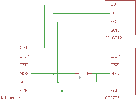
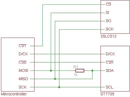
Schaltplan Mikrocontroller mit 25LC512 und ST7735
CS SI SO SCK 25LC512 CST D/CX CSU MOSI MISO SCK Mikrocontroller R1 1k D/CX CSX SDA SCL ST7735
in „SPI Eprom und Display funktionieren nicht zusammen“ · Mikrocontroller und Digitale Elektronik · · Schaltpläne
-
PDF
ch32v003_getting_started.pdf
--------- SPI- Displays ---------------------------- #define ili9163 0 #define ili9340 0 #define st7735r 1 #define s6d02a1 0 #define ili9225 0 #define st7789 0 // ----------------- ST7735R, 2. Generation Controller ------------ // die 128er Display der 2. Generation haben in Verbindung mit // ST7735 eine andere StartColum und RowColum #define st7735r_g2 1 Die oben mittels #define aufgeführten Displaycontroller sind verfügbar. Hier muß (und darf) nur ein einziger Controller ausgewählt werden. Zusätzlich, sollte ST7735R ausgewählt sein, kann st7735r_g2
in „CH32V003: Selbstbauprogrammer und "Getting started"“ · Projekte & Code ·
-
PDF
ch32v003_getting_started.pdf
--------- SPI- Displays ---------------------------- #define ili9163 0 #define ili9340 0 #define st7735r 1 #define s6d02a1 0 #define ili9225 0 #define st7789 0 // ----------------- ST7735R, 2. Generation Controller ------------ // die 128er Display der 2. Generation haben in Verbindung mit // ST7735 eine andere StartColum und RowColum #define st7735r_g2 1 Die oben mittels #define aufgeführten Displaycontroller sind verfügbar. Hier muß (und darf) nur ein einziger Controller ausgewählt werden. Zusätzlich, sollte ST7735R ausgewählt sein, kann st7735r_g2
in „CH32V003: Selbstbauprogrammer und "Getting started"“ · Projekte & Code ·
-
Datei
langemeldung.txt
Dokumente\Arduino\libraries\TimerOne" "C:\Program Files (x86)\Arduino\libraries\TFT\src\utility\Adafruit_ST7735.cpp" -o "nul" "C:\Program Files (x86)\Arduino\hardware\tools\avr/bin/avr-g++" -c -g -Os -w -std=gnu++11 -fpermissive -fno-exceptions -ffunction-sections -fdata-sections -fno-threadsafe-statics -flto
in „Probleme bei kompilieren des Maiskolben-Sketch's“ · Mikrocontroller und Digitale Elektronik ·
-
 Bild
Bild
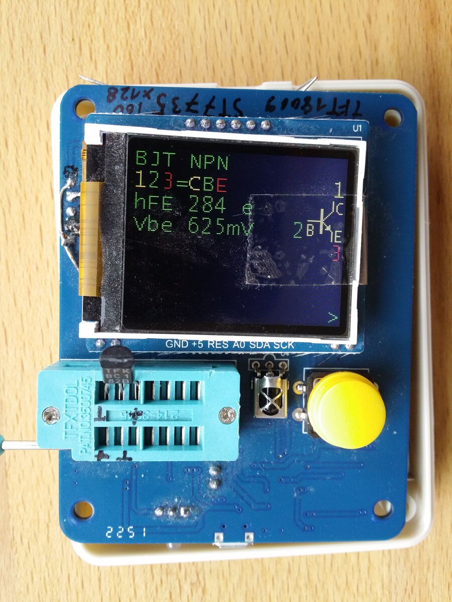
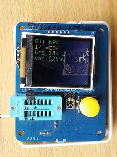
Transistor-Tester-Modul mit Display auf Holzuntergrund
TFT18009 ST7735 160 BJT NPN 123=CBE hFE 284 Vbe 625mV GND +5 RES A0 SDA SCK JFXTDOL PAT04C3500745 2251
in „Transistortester AVR“ · Projekte & Code · · Platinenfotos
-
 Bild
Bild
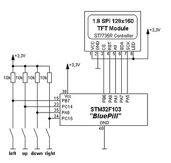
Schaltplan STM32F103 Blue Pill mit TFT-Modul
1.8 SPI 128x160 TFT Module ST7735R Controller VCC GND CS SDA SCK LED +3,3V 10k 10k 10k 38 Vcc PB7 PB6 PA8 PA1 PA7 PA5 23 PC14 25 PA0 24 PC15 GND 40 left up down right
in „Game CodedColor für die STM32F103 Bluepill“ · Projekte & Code · · Schaltpläne
-
 Bild
Bild
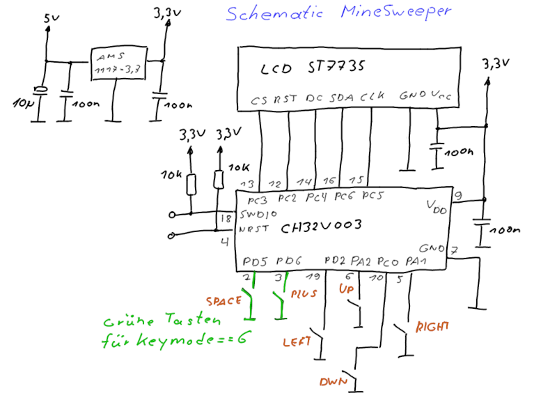
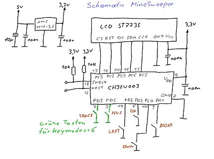
Handgezeichneter Schaltplan für Minesweeper mit LCD und CH32V003
Schematic Minesweeper 5v 3,3v AMS1117-3,3 10u 100n 100n LCD ST7735 CS RST DC SDA CLK GND Vcc 3,3V 3,3V 10k 10k 13 12 14 16 15 PC3 PC2 PC4 PC6 PC5 18 SWDIO CH32V003 4 NRST VDD 9 100n GND 7 PD5 PD6 PD2 PA2 PC0 PA1 2 3 19 5 0 1 SPACE PLUS UP RIGHT LEFT DWN grüne Tasten
in „MineSweeper für CH32V003 (Linux Makefile-Projekt)“ · Projekte & Code · · Schaltpläne
-
 Bild
Bild
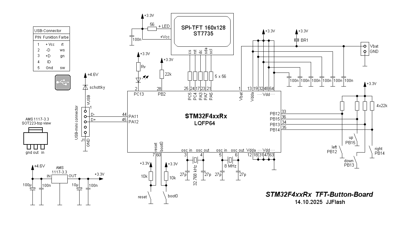
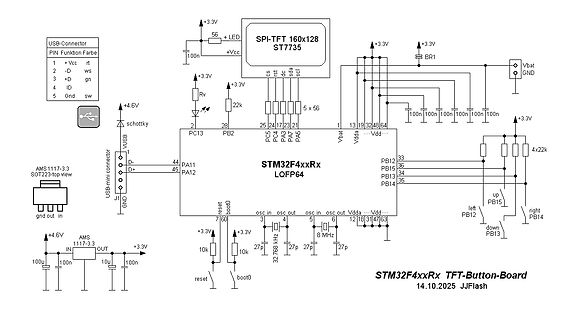
Schaltplan STM32F4xxRx TFT-Button-Board
USB-Connector PIN Funktion Farbe 1 +Vcc rt 2 -D ws 3 +D gn 4 ID 5 GND sw 56 100n +3.3V + LED SPI-TFT 160x128 ST7735 cs rs rdc scl +3.3V BR1 Vbat GND 28 PB2 25 PC5 24 PC4 23 PC3 21 PA5 PA6 1 Vbat 13 Vdda 32 Vdd 48 Vbat 100n 100n 100n 4x22k 3.3V up PB15 left PB12 right PB14 down PB13 J1 GND D+ D- PA12 PA11 AMS1117
in „STM32F4 - Spiele“ · Projekte & Code · · Schaltpläne
-
 Bild
Bild
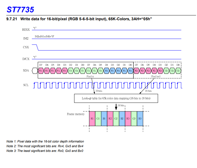
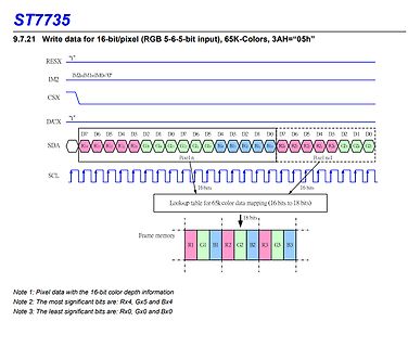
Timing-Diagramm für 16-Bit-Pixeldatenübertragung
ST7735 9.7.21 Write data for 16-bit/pixel (RGB 5-6-5-bit input), 65K-Colors, 3AH="05h" RESX "L" IM2 IM2=IM1=IM0="" CSX "L" D/CX D7 D6 D5 D4 D2 D1 D0 D7 D6 D5 D4 D3 D2 D1 D0 D7 D6 D5 D4 D3 D2 D1 D0 SDA Rx1
in „Probleme mit SPI- PIC18“ · Mikrocontroller und Digitale Elektronik · · Screenshots
-
 Bild
Bild
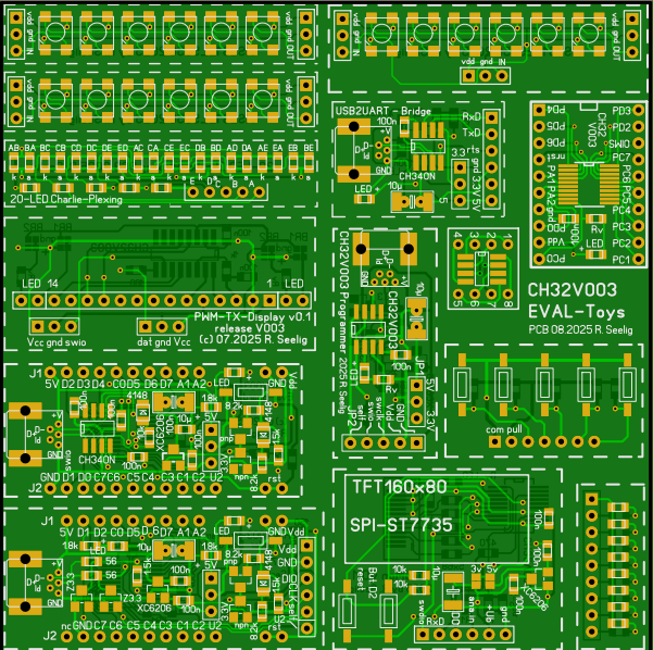
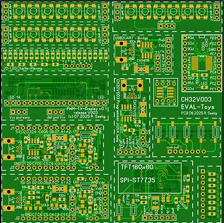
PCB-Layout einer EVAL-Toys CH32V003 Platine
PD4 PD3 PD2 PD0 LED 20-LED Charlie-Plexing CH32V003 Programer 08.2025 R Seelig EVAL-Toys PCB SPI-ST7735 TFT160x80 5V D2 D3 D4 D5 D6 D7 A1 A2 LED GND Vdd 100n 10u 47 10k 1k 47 100n 10u 47 10k 1k 47 100n 10u 47 10k 1k 47 100n 10u 47 10k 1k 47 100n 10u 47 10k 1k 47 100n 10u 47 10k 1k 47 100n 10u 47 10k
in „CH32V003-J4M6: Einfacher Rechteckgenerator 0,5 Hz 20 kHz“ · Projekte & Code · · Layouts
-
 Bild
Bild
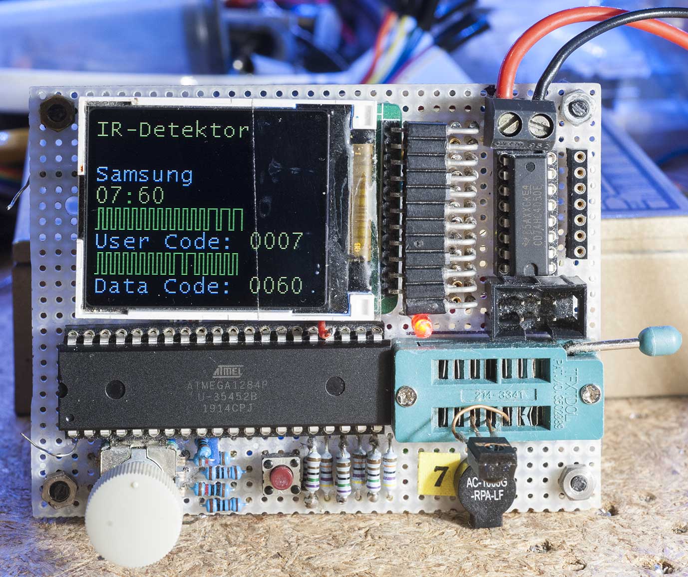
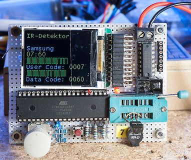
Aufbau mit LCD-Display und ATmega1284P Mikrocontroller
IR-Detektor Samsung 07:60 User Code: 0007 Data Code: 0060 ATMEL ATmega1284P U-35452B 1914CPJ 7 AC-1000G RPA-LF
in „Transistortester AVR“ · Projekte & Code · · Platinenfotos
-
Datei
config_328.h
LCD_SCL /* port pin used for SCK */ #define SPI_MOSI LCD_SI /* port pin used for MOSI */ #endif /* * ST7735 * - 4 wire SPI interface using bit-bang SPI */ #if 0 #define LCD_ST7735 /* display controller ST7735 */ #define LCD_GRAPHIC /* graphic display */ #define LCD_COLOR /* color display */ #define LCD_SPI
in „ComponentTester-1.42m problem“ · Mikrocontroller und Digitale Elektronik ·
-
Datei
config_328.h
LCD_SCL /* port pin used for SCK */ #define SPI_MOSI LCD_SI /* port pin used for MOSI */ //#endif /* * ST7735 * - 4 wire SPI interface using bit-bang SPI */ #if 0 #define LCD_ST7735 /* display controller ST7735 */ #define LCD_GRAPHIC /* graphic display */ #define LCD_COLOR /* color display */ #define LCD_SPI
-
PDF
T7-mod-obelix2007.pdf
PB0 PB1 PB0 PB1 PB2 PB3 PB2 PB4 o PB5 PB3 LCD1_{d} Z180SN009 Parts denoted with _{d}: PB4 s PB5 ST7735S based display board 128x160 On this display board. PB6 a PB7 65k colours PB6 x PB7 1.8" PD6 PD6 E PD5 PD5 5V PD7 VCC 7 PD7 GND J 9V VBOOST VCC A A In-System- VREF } +2V5 T programming. 1 k C E GND
-
PDF
Component_tester_T7-dreieck.pdf
Expansion port. PB0 PB1 PB0 PB1 PB2 PB2 PB3 PB3 PB4 i PB5 LCD1_{d} Parts denoted with _{d}: PB4 s PB5 ST7735S based display boardZ180SN009 On this display board. PB6 a PB7 128x160 PB6 PD6 x PD5 PB7 65k colours PD6 E PD5 5V PD7 1.8" VCC 7 PD7 GND J 9V VBOOST VCC A A In-System- VREF } programming. +2V5 T 1
-
PDF
T7-mod-obelix2007.pdf
Expansion port. PB0 PB1 PB0 PB1 PB2 PB3 PB2 o PB3 LCD1_{d} Parts denoted with _{d}: PB4 PB4 s PB5 PB5 ST7735S based display boardZ180SN009 On this display board. PB6 a PB7 PB6 x PB7 128x160 PD6 PD6 E PD5 PD5 65k colours 5V PD7 1.8" VCC 7 PD7 GND J 9V VBOOST VCC A A VREF In-System- +2V5 T programming. 9 2
-
PDF
T7-mod-obelix2007.pdf
PB0 PB1 PB0 PB1 PB2 PB3 PB2 PB4 o PB5 PB3 LCD1_{d} Z180SN009 Parts denoted with _{d}: PB4 s PB5 ST7735S based display board 128x160 On this display board. PB6 a PB7 65k colours PB6 x PB7 1.8" PD6 PD6 E PD5 PD5 5V PD7 VCC 7 PD7 GND J 9V VBOOST VCC A A In-System- VREF } +2V5 T programming. 1 k C E GND
-
PDF
Component_tester_T7-dreieck.pdf
OVP Expansion port. PB0 PB1 PB0 PB1 PB2 PB3 LCD1_{d} Z180SN009 Parts denoted with _{d}: PB2 o PB3 ST7735S based display board 128x160 PB4 PB4 s PB5 PB5 On this display board. PB6 a PB7 65k colours PB6 x PB7 1.8" PD6 PD6 E PD5 PD5 5V PD7 VCC 7 PD7 GND J 9V VBOOST VCC A A VREF In-System- OVP OVP OVP +2V5
-
PDF
Component_tester_T7-dreieck.pdf
OVP Expansion port. PB0 PB1 PB0 PB1 PB2 PB3 LCD1_{d} Z180SN009 Parts denoted with _{d}: PB2 o PB3 ST7735S based display board 128x160 PB4 PB4 s PB5 PB5 On this display board. PB6 a PB7 65k colours PB6 x PB7 1.8" PD6 PD6 E PD5 PD5 5V PD7 VCC 7 PD7 GND J 9V VBOOST VCC A A VREF In-System- OVP OVP OVP +2V5