-
Datei
ws2812b.c
#include <string.h> //#include "stm32f3xx_hal.h" #include "stm32f1xx_hal.h" #include "ws2812b.h" extern WS2812_Struct ws2812b; // Define source arrays for my DMAs uint32_t WS2812_IO_High[] = { WS2812B_PINS }; uint32_t WS2812_IO_Low[] = {WS2812B_PINS << 16}; // WS2812 framebuffer - buffer for
in „WS2812B mit Lib von Martin Hubáček auf F103“ · Mikrocontroller und Digitale Elektronik ·
-
PDF
Schematic_Aktor_Steuerung_2020-07-13_19-22-06.pdf
GND GND +3.3V +3.3V +5V R6 ESP32-WROOM-32DC CN1 10k XH-5A_C26521 3 5 LED4 LED3 LED2 LED1 D 4 VCC WS2812B WS2812B WS2812B WS2812B N SDA 3 SDA 1 4 1 4 1 4 1 4 C37 1 G 38 SCL 2 SCL 2VDD DIN 3 2 VDD DIN 3 2 VDD DIN 3 2VDD DIN 3 NEoPix1 0.1Fu 2 GND GND 37 IO35 1 OE DOUT VSS DOUT VSS DOUT VSS DOUT VSS 3 3V3
in „Schaltplan kontrolle“ · Mikrocontroller und Digitale Elektronik ·
-
Datei
ws2812b.h
/* WS2812B CPU and memory efficient library Date: 28.9.2016 Author: Martin Hubacek http://www.martinhubacek.cz @hubmartin Licence: MIT License */ #ifndef WS2812B_H_ #define WS2812B_H_ #include "ws2812b.h" // GPIO enable command //#define WS2812B_GPIO_CLK_ENABLE() __HAL_RCC_GPIOC_CLK_ENABLE() #define WS2812B_GPIO_CLK_ENABLE() __HAL_RCC_GPIOA_CLK_ENABLE() // LED output port //#define WS2812B_PORT GPIOC #define WS2812B_PORT GPIOA // LED output
in „WS2812B mit Lib von Martin Hubáček auf F103“ · Mikrocontroller und Digitale Elektronik ·
-
Datei
readme.txt
________________________________ Text und Software von R. Seelig Inhaltsverzeichnis: - Vorwort - WS2812b Leuchtdioden - Make - WS2812b Header - Funktionen von WS2812b . rgbfromvalue . rgbfromega . ws_reset . ws_showarray . ws_clrarray . ws_setrgbcol . ws_setegacol . ws_blendup_left . ws_blendup_right
-
PDF
WS2812B.pdf
WS2812B Intelligent control LED integrated light source Features and Benefits Intelligent reverse connect protection, the power supply reverse connection does not damage the IC. The control circuit and
in „The secret of WS2812B“ · Mikrocontroller und Digitale Elektronik ·
-
PDF
WS2812B_preliminary.pdf
WS2812B Intelligent control LED integrated light source Features and Benefits Intelligent reverse connect protection, the power supply reverse connection does not damage the IC. The control circuit and
in „[Mitbestellung] SMD5050 RGB-LED mit integriertem 8-bit PWM Controller“ · Markt ·
-
PDF
WS2812B.PDF
WS2812B Intelligent control LED integrated light source Features and Benefits Intelligent reverse connect protection, the power supply reverse connection does not damage the IC. The control circuit and
in „Bauteil identifizieren: LB1902“ · Analoge Elektronik und Schaltungstechnik ·
-
PDF
WS2812B.pdf
WS2812B Intelligent control LED integrated light source Features and Benefits Intelligent reverse connect protection, the power supply reverse connection does not damage the IC. The control circuit and
in „LEDs über IR-Sensoren zum leuchten bringen“ · Mikrocontroller und Digitale Elektronik ·
-
PDF
WS2812B.pdf
WS2812B Intelligent control LED integrated light source Features and Benefits Intelligent reverse connect protection, the power supply reverse connection does not damage the IC. The control circuit and
in „ESP32-H2 will nicht schlafen“ · Mikrocontroller und Digitale Elektronik ·
-
PDF
Schaltung_LPC.pdf
PEGELWANDLER 4 L 5 L 6 L 4 L 5 L 6 L DCPRG 23 DCPRG OUT9 17 L4_G LED_DATA_3V3 2 18D LED_DATA DIN WS2812B DOUT DIN WS2812B DOUT DIN WS2812B DOUT VPRG 6 XERR OUT10 18 L4_B 3 A1 B1 17 27 VPRG OUT11 19 L5_R 4 A2 B2 16 IREF OUT12 20 L5_G 5 A3 B3 15 S S S OUT13 21 L5_B 6 A4 B4 14 V V V 2k2 1 GND OUT15 22 L6
in „LPC1756 - WS2812B und Schaltplankontrolle“ · Mikrocontroller und Digitale Elektronik ·
-
PDF
WS2812B_VS_WS2812.pdf
/www.world-semi.com 2. Mechanical properties comparison . The mechanical size and pin drawing of WS2812B The mechanical size and pin drawing of WS2812 Through drawing comparison, it is easy to find that the,, WS2812B WS2812 consistent in size, but the PAD number of the former are reduced to 4 Pin, with
in „[Mitbestellung] SMD5050 RGB-LED mit integriertem 8-bit PWM Controller“ · Markt ·
-
PDF
WS2812B-V5.pdf
WS2812B Ver. No.: V5 Intelligent control LED integrated light source Features and Benefits The control circuit and the LED share the only power source. Control circuit and RGB chip are integrated in a
in „PWM-Signal verstärken“ · Mikrocontroller und Digitale Elektronik ·
-
PDF
WS2812B-V5.pdf
WS2812B Ver. No.: V5 Intelligent control LED integrated light source Features and Benefits The control circuit and the LED share the only power source. Control circuit and RGB chip are integrated in a
in „WS2812B mit 3.3V ansteuern“ · Mikrocontroller und Digitale Elektronik ·
-
PDF
WS2812B__Ver._No._V5__EN_19112715001349.pdf
WS2812B Ver. No.: V5 Intelligent control LED integrated light source Features and Benefits The control circuit and the LED share the only power source. Control circuit and RGB chip are integrated in a
in „Adressierbare RGB LEDs 3.3V gesucht“ · Mikrocontroller und Digitale Elektronik ·
-
PDF
WS2812B_Datasheet_2017.pdf
WS2812B Intelligent control LED integrated light source Features and Benefits The control circuit and the LED share the only power source. Control circuit and RGB chip are integrated in a package of 5050
in „WS2812 Ansteuerung“ · Mikrocontroller und Digitale Elektronik ·
-
PDF
WS2812B-MINI.pdf
WS2812B-Mini Intelligent external control LED Integrated light source Features and Benefits The IC’s control circuit and the LED share the same power supply. Control circuit and RGB chip are integrated
in „Indirekte Beleuchtung mit ca. 30m LED Streifen“ · Analoge Elektronik und Schaltungstechnik ·
-
PDF
WS2812B-V4.pdf
WS2812B-V4 Intelligent control LED integrated light source Features and Benefits The control circuit and the LED share the only power source. Control circuit and RGB chip are integrated in a package of
in „PWM-Signal verstärken“ · Mikrocontroller und Digitale Elektronik ·
-
Bild
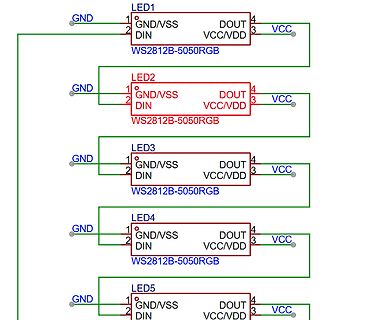
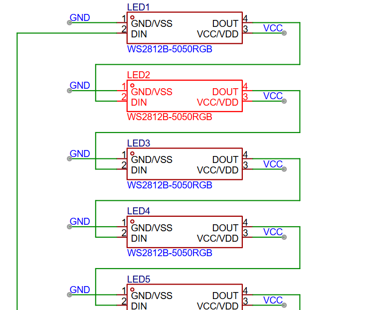
Schaltplan mit fünf WS2812B-5050RGB LEDs
LED1 WS2812B-5050RGB GND/VSS DIN DOUT VCC/VDD VCC GND LED2 WS2812B-5050RGB GND/VSS DIN DOUT VCC/VDD VCC GND LED3 WS2812B-5050RGB GND/VSS DIN DOUT VCC/VDD VCC GND LED4 WS2812B-5050RGB GND/VSS DIN DOUT VCC/VDD VCC GND LED5 WS2812B-5050RGB GND/VSS DIN DOUT VCC/VDD VCC GND
in „ESP32 und 240Stück WS2812B“ · Mikrocontroller und Digitale Elektronik · · Schaltpläne
-
Datei
ws2812b.h
#ifndef WS2812B #define WS2812B #ifdef STM32F10X_MD #include <stm32f10x.h> #include <irq_stm32f103.h> #endif #if defined(STM32F303xE) || defined(STM32F303xD) || defined(STM32F303xC) #include <stm32f3xx.h> #include
in „WS2812b Pixel mit STM32 und PWM/DMA ohne Hal“ · Mikrocontroller und Digitale Elektronik ·
-
Bild
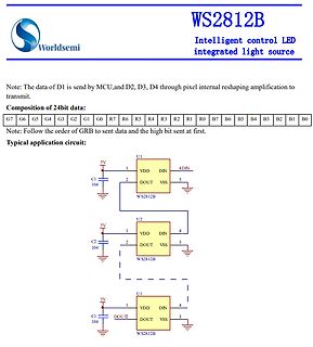
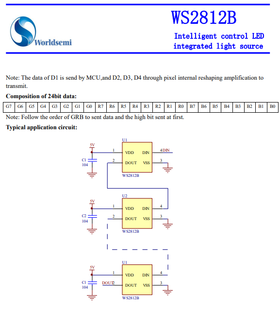
Datenblatt Ausschnitt WS2812B LED Treiber
WS2812B Intelligent control LED integrated light source Note: The data of D1 is send by MCU,and D2, D3, D4 through pixel internal reshaping amplification to transmit. Composition of 24bit data: G7 G6 G5 G4
in „Problem mit WS2812b 4-Layer Board“ · Mikrocontroller und Digitale Elektronik · · Screenshots
-
PDF
4xRGB-LED-Steuern-5V_SCH.PDF
- 2 2 2 2 + 0 3- 1 7 2 7 3 7 4 7 2 R 4 R 4 R 1 4 R 4 1+ 1 1 1 K2 RGB-LED Daten Klemme 4 3 2 1 K3 WS2812B 3 VSS Dout 2 4 Din VDD 1 D4 WS2812B VSS Dout 3 2 4 Din VDD 1 D3 WS2812B 3 VSS Dout 2 Din VDD 4 1 D2 WS2812B VSS Dout 3 2 4 Din VDD 1 D1
in „empehlung Microcontroller WS2812B Steuern“ · Mikrocontroller und Digitale Elektronik ·
-
Datei
readme.txt
________________________________________ 10.11.2018 by R. Seelig Inhaltsverzeichnis: - Vorwort - WS2812b Leuchtdioden - Make - WS2812 Header . ws2812.h . ws2812_pins.h - Funktionen von WS2812 . rgbfromega . rgbfromvalue . ws_showbuffer . ws_setrgbcol . ws_reset . ws_init . ws_clrarray . ws_blendup_left
-
Bild
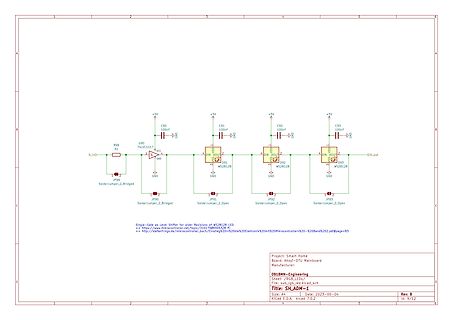
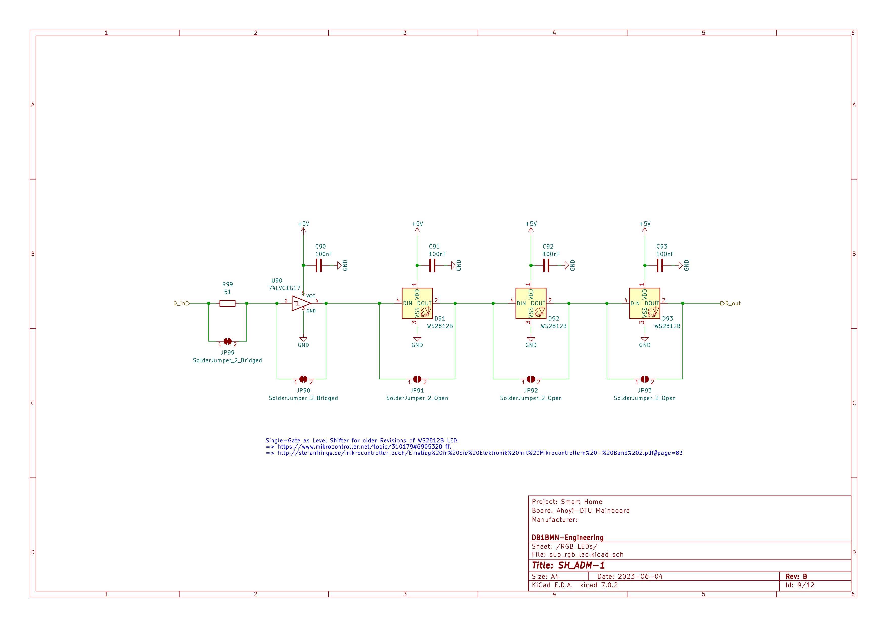
Schaltplan eines LED-Treiberschaltkreises
S1, U90 74LVC1G17, D_in, GND, +5V, C90 100nF, JP99 SolderJumper_2_Bridged, JP90, C91 100nF, D91 WS2812B, DIN, DOUT, JP91 SolderJumper_2_Open, GND, C92 100nF, D92 WS2812B, DIN, DOUT, JP92 SolderJumper_2_Open, C93 100nF, D93 WS2812B, DIN, DOUT, D_out, Project: Smart Home, Board: Anydot-DTU Mainboard,
in „Wortuhr Dioden Multiplex entstören“ · Analoge Elektronik und Schaltungstechnik · · Schaltpläne
-
Datei
Treppenbeleuchtung-WS2812B.ino
#include <Adafruit_NeoPixel.h> #include <Wire.h> #ifdef __AVR__ #include <avr/power.h> #endif /*******************************Variablendeklaration***********************************/ int Melder_unten = 22; // Input Bewegungsmelder unten int Melder_oben = 23; // Input Bewegungsmelder oben int Nanopixel = 6; // Output für NanoPixel LEDs int VZ = 15; // Verzögung Ansteuerung der Stufen int Dauer = 30000; // Leuchtdauer wenn alle Stufen angesteuert sind int Sperrzeit = 60000; // Sperrzeit bevor die Scheife beendet wird und die anderen Laufen kann bool BWU,BWO; float PIXEL; #define NUMPIXELS 394 // Anzahl
in „Dynamischer Variablenname in Scheife hochzählen“ · Mikrocontroller und Digitale Elektronik ·
-
Datei
LED_WS2812B.c
############################################################################# // Steuerung von 5 WS2812B über einen beliebigen Port //################################################################################### #include <avr/io.h> #include <util/delay.h> #include <avr/interrupt.h> #include <avr
in „WS2812 Ansteuerung per Bitbanging für AVR und ARM von 4 Mhz-60 Mhz“ · Projekte & Code ·
-
Datei
LED_WS2812B.c
############################################################################# // Steuerung von 5 WS2812B über einen beliebigen Port //################################################################################### #include <avr/io.h> #include <util/delay.h> #include <avr/pgmspace.h> #include "light_ws2812
in „WS2812 Ansteuerung per Bitbanging für AVR und ARM von 4 Mhz-60 Mhz“ · Projekte & Code ·
-
Datei
3-farben-fader.bas
'3-Farben-fader mit WS2812b $regfile = "attiny13a.dat" $crystal = 9600000 $hwstack = 16 $swstack = 16 $framesize = 7 $lib "Rainbow.lib" 'implementierung $external Ws2812b 'Driver Declare sub BOW_INIT() Declare Sub Bow_reset() Declare Sub Bow_clear(byval Set_direct As Byte) Declare sub BOW_Select(Bylabel WS2812b_Channel as Word) Declare Sub Bow_setcolor(byval Lednr As Word , Byval Color As Long , Byval Set_direct As Byte) Const Send = 1 Const Nosend = 0 Const Nosettablecolor = 1 Const Noswap = 1 Const Norotate
in „3x LED-PWM-Faden“ · Mikrocontroller und Digitale Elektronik ·
-
Bild
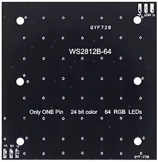
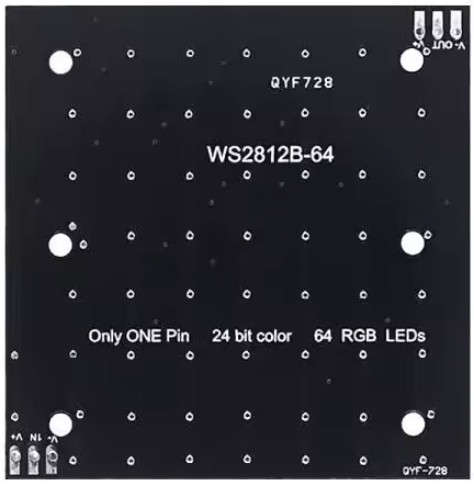
Leiterplatte mit WS2812B-64 RGB LEDs
QYF728 WS2812B-64 Only ONE Pin 24 bit color 64 RGB LEDs V+ IN V- OUT QYF-728
in „China SUPER Bauteile-Schnäppchen Thread [V4]“ · Markt · · Platinenfotos
-
Bild
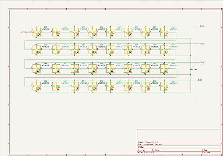
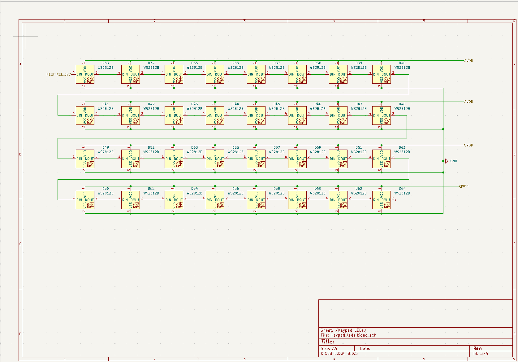
Schaltplan für WS2812B LED-Matrix
D33 bis D64 WS2812B DIN DOUT QVDO GND Sheet: /Keypad LEDs/ File: keypad_leds.klcd_sch Size: A4 Date: Rev: Id: 3/4
in „Problem mit WS2812b 4-Layer Board“ · Mikrocontroller und Digitale Elektronik · · Schaltpläne
-
PDF
Schematic_SIMInterface-Base_Schaltplan_20190313164157.pdf
Connector 17 A1 GPA4 26 12 28 1 MISO +5 2 +5V R9 A2 GPA5 27 11 27 Solder Jumper to run 1K GPA6 10 26 WS2812b with 5V USB 3 4 18 RESET GPA7 28 9 25 power (only in special cases) SCK MOSI 8 24 5 6 20 INTA 7 23 RESET GND 19 INTB GPB0 1 6 22 2 14 GPB1 3 5 21 11 NC GPB2 4 4 20 NC GPB3 3 19 DSP-NEXTION GPB4 5
in „ATMEGA32U4 Schaltplan“ · Mikrocontroller und Digitale Elektronik ·
-
Bild
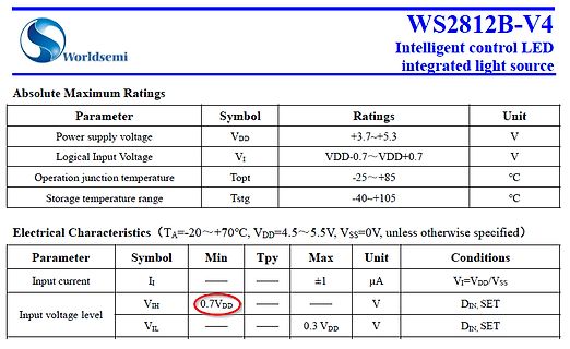
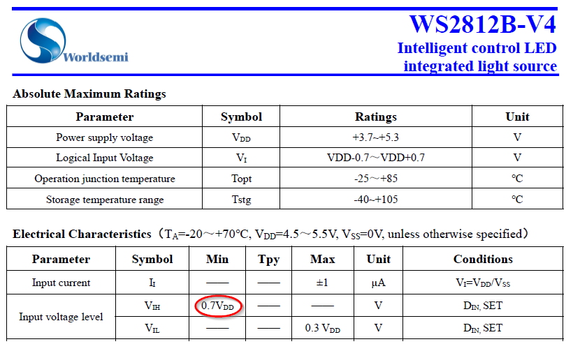
Datenblattabschnitt WS2812B-V4 LED-Lichtquelle
WS2812B-V4 Intelligent control LED integrated light source Absolute Maximum Ratings Parameter Symbol Ratings Unit Power supply voltage VDD +3.7~+5.3 V Logical Input Voltage VI VDD-0.7~VDD+0.7 V Operation
in „Max Schaltpegel DIN NeoPixel WS2812b / WS2813“ · Mikrocontroller und Digitale Elektronik · · Screenshots
-
Bild
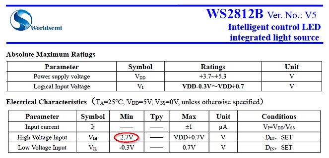
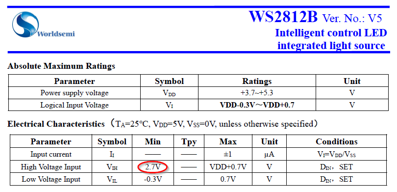
Ausschnitt eines Datenblatts für WS2812B LED-Treiber
WS2812B Ver. No.: V5 Intelligent control LED integrated light source Absolute Maximum Ratings Parameter Symbol Ratings Unit Power supply voltage VDD +3.7~+5.3 V Logical Input Voltage VI VDD-0.3V~VDD+0.7 V
in „Max Schaltpegel DIN NeoPixel WS2812b / WS2813“ · Mikrocontroller und Digitale Elektronik · · Screenshots
-
PDF
Anleitung-Wort-Uhr.pdf
UHR Version 2.2.0 Pegelanpassung Der ESP arbeitet intern mit einer Betriebsspannung von 3,3V. Die WS2812(B) Streifen arbeiten dagegen mit 5V. Dies erfordert eine Pegelanpassung, damit die digitalen Signale fehlerfrei zu den Stripes übertragen warden können. Ohne Anpassung kann es auch funktionieren, muss
in „Wortuhr Dioden Multiplex entstören“ · Analoge Elektronik und Schaltungstechnik ·
-
Bild
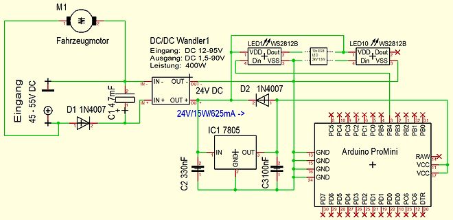
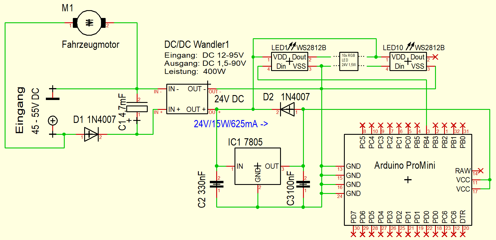
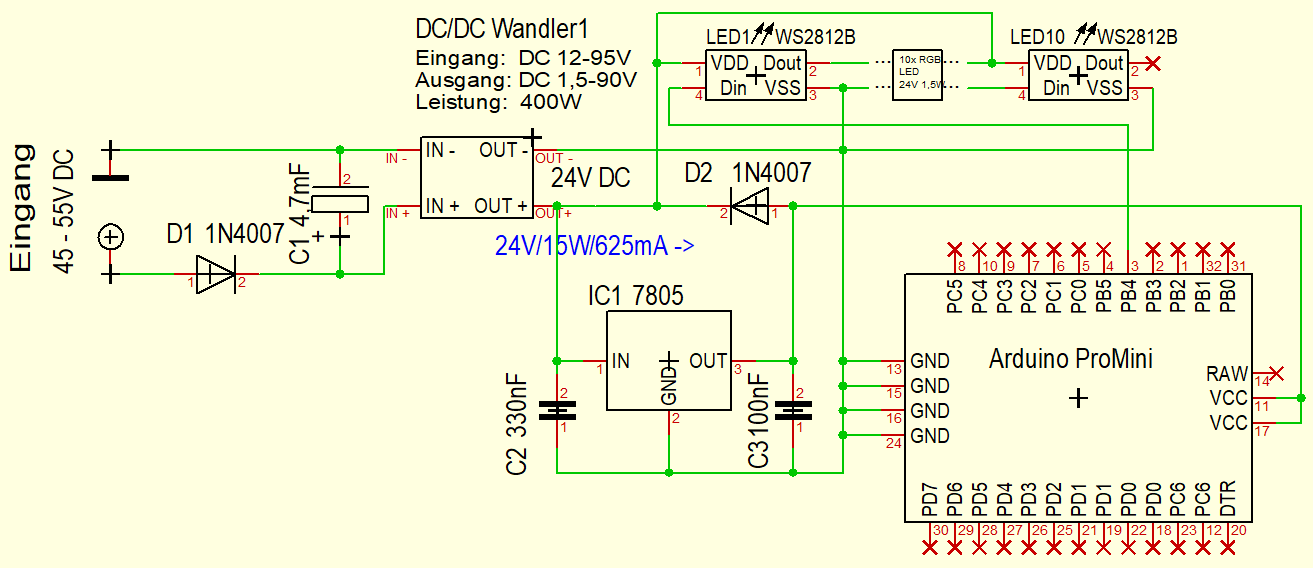
Schaltplan mit DC/DC-Wandler, Motor und Arduino ProMini
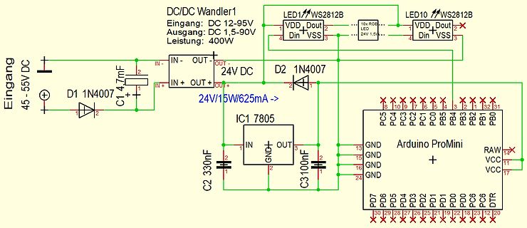
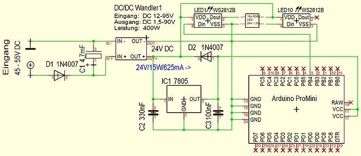
M1 Fahrzeugmotor, DC/DC Wandler1, Eingang: DC 12-95V, Ausgang: DC 1,5-90V, Leistung: 400W, LED1 WS2812B, LED10 WS2812B, 24V 1,5W, Eingang 45-55V DC, D1 1N407, C1 4,7mF, 24V/15W/625mA, D2 1N407, IC1 7805, C2 330nF, C3 100nF, Arduino ProMini, PC5 bis PC0, PB5 bis PB1, PB0, RAW, VCC, DDR, DT, PD0 bis PD7
in „DCDC Wandler sterben - Schutzmaßnahmen?“ · Analoge Elektronik und Schaltungstechnik · · Schaltpläne
-
Bild
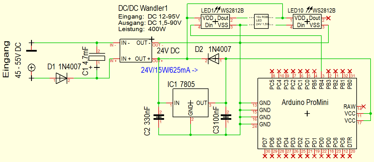
Schaltplan mit Arduino ProMini und DC/DC Wandler
DC/DC Wandler1 Eingang: DC 12-95V Ausgang: DC 1,5-90V Leistung: 400W LED1 WS2812B LED10 WS2812B VDD Dout VSS Din 24V 1,5V Eingang 45-55V DC D1 1N4007 C1 4,7mF IN- OUT- OUT+ IN+ OUT+ 24V DC D2 1N4007 IC1 7805 24V/15W/625mA -> C2 330nF C3 100nF IN GND OUT GND GND GND Arduino ProMini
in „DCDC Wandler sterben - Schutzmaßnahmen?“ · Analoge Elektronik und Schaltungstechnik · · Schaltpläne
-
Bild
Schaltplan mit DC/DC-Wandler, Arduino ProMini und LEDs
DC/DC Wandler1 Eingang: DC 12-95V Ausgang: DC 1,5-90V Leistung: 400W LED1 WS2812B LED10 WS2812B 24V 1,5W VDD Dout Din VSS Eingang 45-55V DC D1 1N4007 C1 4,7mF IN- OUT- 24V DC IN+ OUT+ D2 1N4007 24V/15W/625mA -> IC1 7805 IN GND OUT C2 330nF C3 100nF Arduino ProMini GND GND GND RAW
in „DCDC Wandler sterben - Schutzmaßnahmen?“ · Analoge Elektronik und Schaltungstechnik · · Schaltpläne
-
PDF
Beschreibung_Steuerungssoftware_und_Platinenlayout.pdf
voneinander abhängiges Bewegungsschema vorwärts-rückwärts-Drehung rechts-Drehung links - Steuern von einem WS2812B RGB LED Ring mit 24-32 LEDs - Bedienung über Balkenmenu auf SH1106-OLED-Display 128 x 64 Pixel - Menu-Steuerung über Drehgeber - Menu viersprachig (DE, EN, FR, ES) Alle Einstellungen bei Veränderung
in „Unterstützung gesucht, Micropython & Platinenlayout“ · Markt ·
-
Datei
light_ws2812.c
/* * light weight WS2812 lib V2.0b * * Controls WS2811/WS2812/WS2812B RGB-LEDs * Author: Tim (cpldcpu@gmail.com) * * Jan 18th, 2014 v2.0b Initial Version * * License: GNU GPL v2 (see License.txt) */ #include "light_ws2812.h" #include <avr/interrupt.h> #include <avr/
in „ws2812 mit atmega32“ · Mikrocontroller und Digitale Elektronik ·
-
Datei
lightws.c
/* * light weight WS2812 lib V2.0b * * Controls WS2811/WS2812/WS2812B RGB-LEDs * Author: Tim (cpldcpu@gmail.com) * * Jan 18th, 2014 v2.0b Initial Version * * License: GNU GPL v2 (see License.txt) */ #include "lightws.h" #include <avr/interrupt.h> #include <avr/io.h>
in „arrays und struct in funktionen“ · Mikrocontroller und Digitale Elektronik ·
-
Datei
light_ws2812.c
/* * light weight WS2812 lib V2.0b * * Controls WS2811/WS2812/WS2812B RGB-LEDs * Author: Tim (cpldcpu@gmail.com) * * Jan 18th, 2014 v2.0b Initial Version * Nov 29th, 2015 v2.3 Added SK6812RGBW support * * License: GNU GPL v2+ (see License.txt) */ #include "light_ws2812
in „LED-Matrix mit light_ws2812-library; Ansteuerungsgeschwindigkeit“ · Mikrocontroller und Digitale Elektronik ·
-
Datei
light_ws2812.c
/* * light weight WS2812 lib V2.0b * * Controls WS2811/WS2812/WS2812B RGB-LEDs * Author: Tim (cpldcpu@gmail.com) * * Jan 18th, 2014 v2.0b Initial Version * Nov 29th, 2015 v2.3 Added SK6812RGBW support * * License: GNU GPL v2+ (see License.txt) */ #include "light_ws2812
in „Neopixel Attiny85 Makefile Probleme“ · Mikrocontroller und Digitale Elektronik ·
-
Datei
light_ws2812.c
/* * light weight WS2812 lib V2.0b * * Controls WS2811/WS2812/WS2812B RGB-LEDs * Author: Tim (cpldcpu@gmail.com) * * Jan 18th, 2014 v2.0b Initial Version * Nov 29th, 2015 v2.3 Added SK6812RGBW support * * License: GNU GPL v2 (see License.txt) */ #include "light_ws2812
in „Kann mit Light WS2812 nicht mehr als 128 LEDs ansteuern“ · Mikrocontroller und Digitale Elektronik ·
-
Datei
Sperlings_VU_UNO.ino
AMBILIGHTBRIGHTNESS = 75; # define COLOR_ORDER GRB // Colour order of LED strip [GRB] # define LED_TYPE WS2812B // LED string type [WS2812B] # define DC_OFFSET 0 // DC offset in aux signal [0] # define NOISE 0 // Noise/hum/interference in aux signal [0] # define SAMPLES 64 // Length of buffer for dynamic level
in „Arduino Sketch mittels Kippschalter anders "loopen" lassen“ · Projekte & Code ·
-
Bild
-
Bild
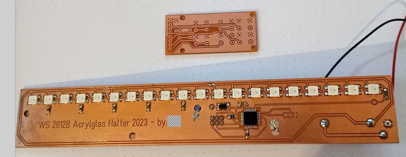
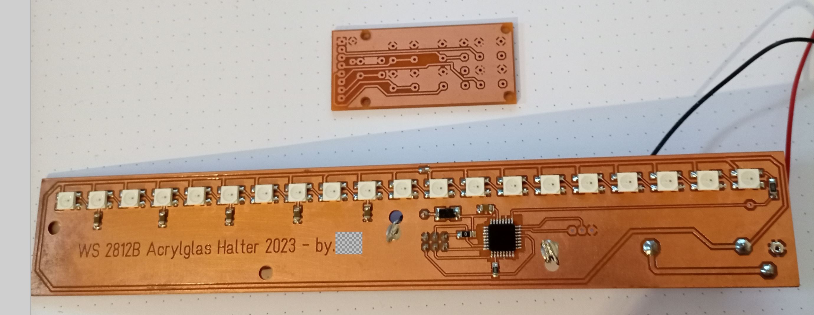
Zwei geätzte Leiterplatten mit LEDs und IC
WS 2812B Acrylglas Halter 2023 - by
in „Hilfestellung bei der Auswahl des richtigen PCB-Prototypen-Erstellungswerzeugs“ · Platinen · · Platinenfotos
-
Bild
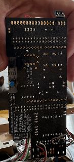
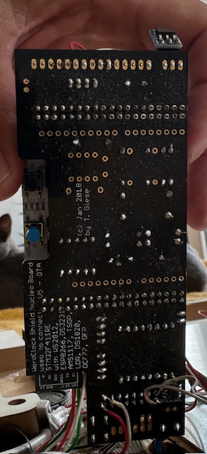
Rückseite einer Leiterplatte mit Beschriftung
(c) Jan 2018 by T. Giese used to connect: Nucleo Board U5 with WS2812B, DS3231, ESP8266, DS18B20, AMS1117, DS1820, DCF77, DFROBOT
in „WordClock mit WS2812“ · Projekte & Code · · Platinenfotos
-
Bild
Screenshot einer AliExpress Produktseite für ein BMS
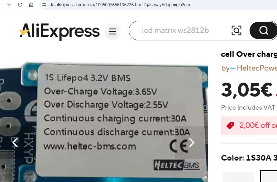
AliExpress led matrix ws2812b 1S Lifepo4 3.2V BMS Over-Charge Voltage:3.65V Over Discharge Voltage:2.55V Continuous charging current:30A Continuous discharge current:30A www.heltec-bms.com CE HELTEC BMS 3,05€ Price includes VAT
in „4s LiFePO4: Schutzschaltung (BMS) mit 3,0V/3,5V gesucht“ · Analoge Elektronik und Schaltungstechnik · · Screenshots
-
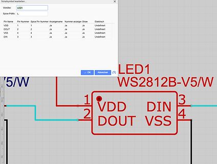
Bild
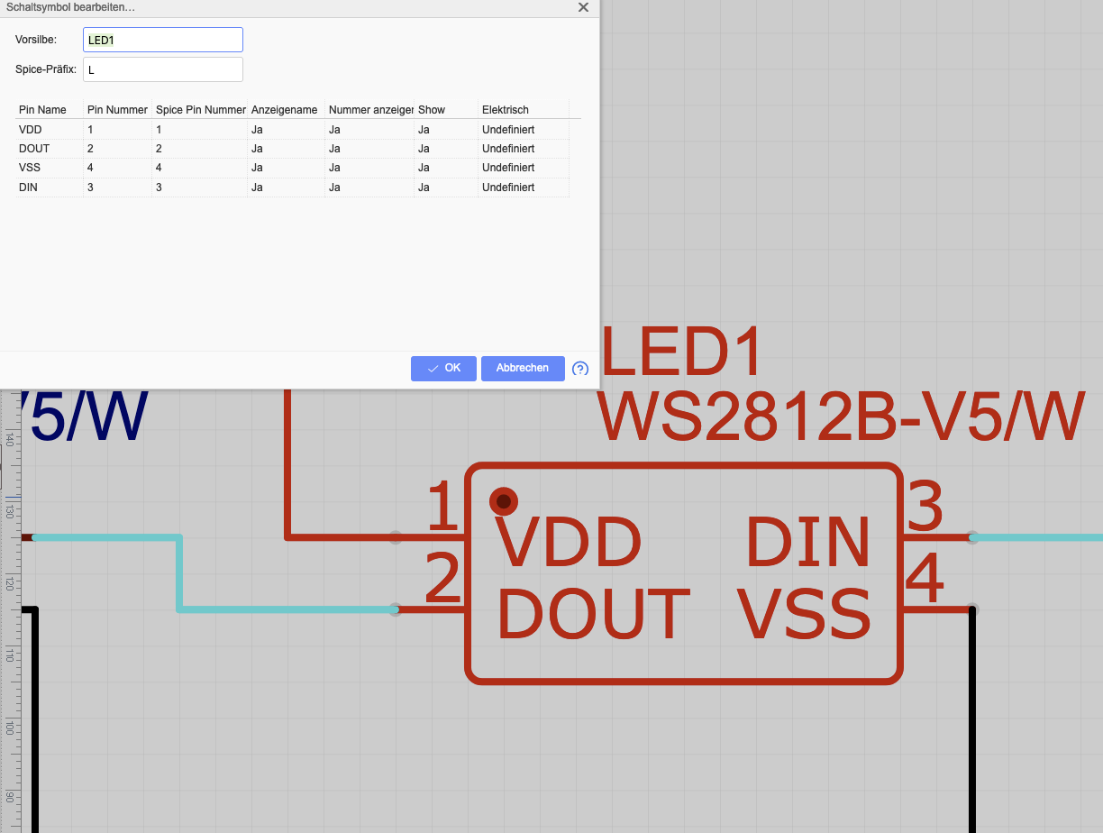
Software-Dialog zur Bearbeitung eines Schaltplansymbols
Ja Ja Ja Undefiniert VSS 4 4 Ja Ja Ja Undefiniert DIN 3 3 Ja Ja Ja Undefiniert OK Abbrechen LED1 WS2812B-V5/W 1 VDD 3 2 DOUT DIN 4 VSS
in „Platine mit LEDs (WS2812B V5) funktionert nicht“ · Platinen · · Screenshots
-
Bild
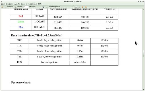
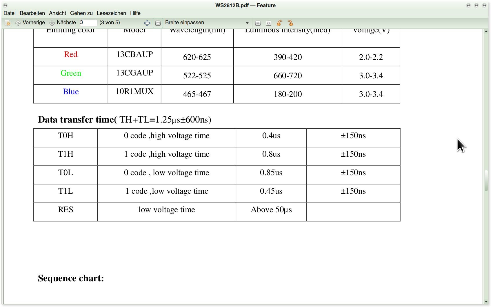
Tabelle mit technischen Daten zu Farben und Übertragungszeiten
WS2812B.pdf - Feature Red 13CBAUP 620-625 390-420 2.0-2.2 Green 13CGAUP 522-525 660-720 3.0-3.4 Blue 10R1MUX 465-467 180-200 3.0-3.4 Data transfer time( TH+TL=1.25µs±600ns) T0H 0 code, high voltage time 0.4us
in „RGB Led Band von Action“ · Mikrocontroller und Digitale Elektronik · · Screenshots
-
Datei
WS2812Ctrl.h
--------------------------------------------------------- WS2812Ctrl.h Control of LED Strip with WS2812B driver ----------------------------------------------------------------------- Last committed: $Revision: 05 $ Last changed by: $Author: Thomas.Stief@web.de$ Last changed date: $Date: 04.05.2015 $