Guten Tag, den Winkelgeber AS5600 möchte ich mit einem LPC 1768 über I2C ansteuern. Das I2C Protokoll schein auch zu funktionieren, weil das Ack vom Baustein einwandfrei kommt. Allerdings sind die Daten unplausibel und mir ist nicht
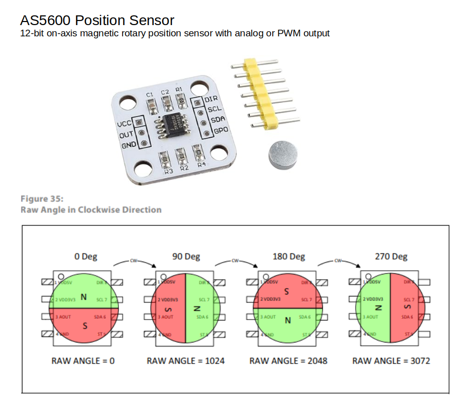
AS5600 Position Sensor
12-bit on-axis magnetic rotary position sensor with analog or PWM output
C1 C2 R1 DIR
UCC SCL
OUT SDA
GND GPO
R3 R2 R4
Figure 35:
Raw Angle in Clockwise Direction
0 Deg 90 Deg 180
Ich betreibe einen AS5600 Winkelsensor an einem Arduino am Analog-Eingang. Der Sensor liefert 0..5V je nach Winkel; der Arduino macht daraus 0..1024 (10 Bit A/D-Wandler) Ansich ganz einfach und schnell aufgebaut, aber der
The connector board permits a simple and quick assessment of the AS5600 revolving attractive position sensor in the lab or along with a current framework https://www.dqfansurvey.org/
Guten Tag, ich beschäftige mich derzeit mit i2C. Ich möchte mit dem AS5600 den Winkel eine Welle auslesen, klappt auch sowit alles über die Lib für den AS5600. Allerdings möchte ich weg von der Lib und selber alles über i2c machen. Mit dem Hintergrund, dass ich später das
return 0xFFFF; // error } error = Wire.requestFrom(AS5600adr,2); // request 2 bytes from slave if(error) { wireError(error); return 0xFFFF; // error } if(2 == Wire.available()) { // slave may send less than requested unsigned
funktionierend aber leider ist die Datei verschwunden ò_Ò. Ich möchte derzeit erstmal nur den RAW Angle ausm AS5600 auslesen mit meinen PIC18f. Code übern MCC generiert weil ich weiß, dass es mal funktioniert hat. Aber es kommt nur komsiches Zeug bei raus. Ausgeben lasse ich es aufn einen kleinen OLED Display
magnetische Drehgeber. Vermutlich immer noch. > Nun wollte ich diese ersetzen durch eventuelle wie AS5600 Du möchtest also grob gesagt nur die Mechanik erhalten, und die Platinen komplett ersetzen ? Da der AS5600 einen Analogausgang hat, musst du dich um kein Protokoll kümmern. Da du den AS5600
hier ist ein Arduino Demo Shield für deinen Sensor. https://www.mouser.at/new/ams-osram/ams-as5600-potuino-arduino-shield/ sg & gute Fahrt
>AS5600 https://www.mouser.de/new/ams-osram/ams-as5600-potuino-arduino-shield/ https://www.mouser.de/datasheet/2/588/AS5600_AB-POT_UG000378_1-00-1513605.pdf allerdings 51,32 € Es gibt auch immer noch
Christoph db1uq K. schrieb im Beitrag #7359665: >>AS5600 > https://www.mouser.de/new/ams-osram/ams-as5600-potuino-arduino-shield/ > https://www.mouser.de/datasheet/2/588/AS5600_AB-POT_UG000378_1-00-1513605.pdf > allerdings 51,32 € https://www.mouser.de
Ich habe mich bei der Bestellung der Sensoren für ein Projekt verschaut und versehentlich AS5600 anstatt AS5600L gekauft. Das bedeutet ich habe etliche Sensoren die alle mit der selben unveränderlichen Adresse am I2C Bus hängen. Klar könnte ich einen Busmultiplexer verwenden oder die richtigen
macht der AS5600 nicht und als Master kann er auch nicht agieren. Barny F. schrieb im Beitrag #7909999: > Das bedeutet ich habe etliche Sensoren die alle mit der selben > unveränderlichen Adresse am I2C Bus
den ESP32 dann für 30 Minuten in den Tiefschlaf schicken. Also sammel ich hier mal - AAT001 - AS5600 - Board billig bei Ali zu bekommen (1,70 €), läuft mit 3,3 Volt. - AS5147
Hab jetzt mal für ~10€ sechs Stück von diesen AS5600 bestellt: https://www.aliexpress.com/item/1005006144589601.html Thema erledigt.
man > die Präzision braucht. das heißt, ich bräuchte einen Präzisions-Drehwertgeber, um meinen AS5600 Sensor zu kalibrieren? Das wäre dann doch etwas viel Aufwand!
einen kleinen Schrittmotor nehmen und die Schritte zählen. So könnte ich bei jedem Step den Wert vom AS5600 lesen und die Kurve aufnehmen.
at F (nm) at F (V) at F TECHNOLOGY MIN. TYP. MAX. (mA) MIN. TYP. MAX. (mA) MIN. TYP. MAX. (mA) TLPR5600 Red 1 3.5 - 10 - 630 - 10 - 2 3 20 GaAsP on GaP TLPR5600-AS12Z Red 1 3.5 - 10 - 630 - 10 - 2 3 20 GaAsP on GaP TLPH5600 Red 0.63 3.5 - 10 612 - 625 10 - 2 3 20 GaAsP on GaP TLPY5600 Yellow 0.63 2.25 - 10 581 - 594 10 - 2.4 3 20 GaAsP on GaP TLPY5600-ASZ Yellow 0.63 2.25 - 10 581 - 594 10 - 2.4 3 20 GaAsP on GaP TLPG5600 Green 0.63 2.25 - 10 562 - 575 10 - 2.4 3 20 GaP on GaP TLPG5600-AS12Z Green 0.63 2.25 - 10 562 - 575 10 - 2.4
Christoph M. schrieb im Beitrag #7646784: > Ich verwende einen Sensor, der dem AS5600 ähnlich ist Das ist ja nichtmal Salami, das sind Blutwurstscheiben. Die fake news wirst du selber essen müssen.
Sin/Cos-Ausgang. Christoph M. schrieb im Beitrag #7646784: > Ich verwende einen Sensor, der dem AS5600 ähnlich ist. Und der wäre ...?
Pin #2 is a No Connect. For the HEDS-5540 and HEDM-5540, Pin #2 is CH. I, the index output. HEDS-5600/5640,HEDM-5600 *Note: For the HEDS-5600 and HEDM-5600, Pin #2 is a No Connect. For the HEDS-5640, Pin #2 is CH. I, the index output. 2 PackageDimensions HEDM/HEDS-5x8xandHEDM/HEDS-5x9x 3 TheoryofOperation
from 1.2VDC to within 50V of the input voltage with two external resistors, RF1 and RF2. The • HIP5600IS UL Recognized Eval1 Board is configured to provide 15VDC output from a high voltage DC input (such as rectified AC). A zener diode • Adjustable DC Output Voltage 1.2VDC to V IN- 50V can be used to replace
Ströme? Der Controller kennt nur 5V und 5600 Ohm aber weder Leitungswiderstand noch Widerstand des PT100, wobei der Leitungswiderstand schon vorher gemessen werden müsste... D.h. der Fehler wäre hier schon 0.077957 / (5 / 5600) = 87.31184 Ohm
fiber Third Edition, November 2010 model—the rear panels of the NPort 5650 have a link indicator, as Front panel of the NPort 5650-T Series described in the following table. 1. Overview LED Name LED Color LED Function Link Off Fiber disconnected. Welcome to the Moxa NPort 5600 Series. The NPort 5610
Package Color Type Technology Angle of Half Intensity 〉 ö High efficiency red TLHR52../TLHR62.. GaAsP on GaP 14° Yellow TLHY52../TLHY62.. GaAsP on GaP 14° Green TLHG52../TLHG62.. GaP on GaP 14° Description 96 11663 The TLH.52.. and 62.. series was developed for standard applications like general indicating
Was soll das "Kiosk-System" >machen? Das OS (CE oder Embedded) soll ausgesucht werden für dieses as well as für weitere Projekte. Was dieses Kiosk-System angeht, soll ein Ethernet-to-RS485 Interface gebaut werden (1Ethernet auf 16, 32 RS485 Ausgänge), mit einem TFT-Touch zur Konfiguration. Wahrscheinlich
bloß alle 16 / 32 RS485 > Ports in einem Gerät drinnen sein. http://www.moxa.com/product/NPort_5600.htm Matthias
reasonable agreement with 0.026T* T e-q 295 600 measured sensitivity. R = 0.026T e T = 1.15 e T 11350 5600 295295 x 6.4 x11350 120 T T Seri0.02 RVt0.026T eopTrtionaltote1.15atuTe.Assuming 11350 5600 6 W at room temperat-7e, 2 = T e RV=is the constant mentioned above,e6T00 R + R C R 9S V 6.4 x 10 x 120
returns a colon after executing the command. There are two types of parameters. One is fixed such as ON, OFF, or 21. Other is a step parameter such as INC, DEC or INIT. INC: increments the parameter by one. DEC: decrements the parameter by one. INIT: initializes the parameter. 2.2. Get command format
operating systems with respect to their impact on the health and safety of our employees and the public, as well as their impact on the environment. It is particular concern to control or eliminate releases of those substances into theatmospherewhichareknownas ozone depleting substances (ODSs). The Montreal
operating systems with respect to their impact on the health and safety of our employees and the public, as well as their impact on the environment. It is particular concern to control or eliminate releases of those substances into theatmospherewhichareknownas ozone depleting substances (ODSs). The Montreal
operating systems with respect to their impact on the health and safety of our employees and the public, as well as their impact on the environment. It is particular concern to control or eliminate releases of those substances into theatmospherewhichareknownas ozone depleting substances (ODSs). The Montreal
operating systems with respect to their impact on the health and safety of our employees and the public, as well as their impact on the environment. It is particular concern to control or eliminate releases of those substances into theatmospherewhichareknownas ozone depleting substances (ODSs). The Montreal
korrekt? In Tests habe ich gesehen, dass diese manchmal "frei drehen". Die Idee von Uwe mit dem as5600 hat uns gut gefallen. Die Idee von Gabi mit der Gabellichtschranke ist klasse. Bei uns aber aufgrund der Umgebung auf der Modellbauplatte nicht einsetzbar. Jobst Q. schrieb im Beitrag #6993278
operating systems with respect to their impact on the health and safety of our employees and the public, as well as their impact on the environment. It is particular concern to control or eliminate releases of those substances into theatmospherewhichareknownas ozone depleting substances (ODSs). The Montreal
operating systems with respect to their impact on the health and safety of our employees and the public, as well as their impact on the environment. It is particular concern to control or eliminate releases of those substances into theatmospherewhichareknownas ozone depleting substances (ODSs). The Montreal
Hi Forum, Folgendes Teil hat der Postbote heute ausgeworfen: HT2205 Bürstenlosen Motor mit AS5600 Encoder https://de.aliexpress.com/item/4000979603718.html?spm=a2g0s.9042311.0.0.3b704c4d7nTw37 (12V, 1A Haltestrom) und nun bräuchte ich Hilfe bei der Auslegung / Ansteuerung / Auswahl vom
ich davon aus, dass die Treiber um das zu steuern die Position brauchen. Die weiss zwar ich über den AS5600 aber die Motortreiber ICs nicht. Oder verstehe ich da etwas falsch?
13YWA Common Anode, Rt & Lt Hand Decimal SA08-21YWA Common Anode, Rt Hand Decimal SC08-11YWA YELLOW (GaAsP/GaP) 1400 5600 Common Cathode Rt. Hand Decimal SC08-12YWA Common Cathode Lt. Hand Decimal SC08-13YWA Common Cathode Rt. & Lt Hand Decimal SC08-21YWA Common Cathode Rt. Hand Decimal SA08-11SRWA Common
(GaP) 560 1400 DC04-14HWA Common Cathode DA04-11EWA DA04-14EWA Common Anode HIGH EFFICIENCY RED (GaAsP/GaP) 2200 5600 DC04-11EWA Common Cathode DC04-14EWA DA04-11GWA Common Anode DA04-14GWA GREEN (GaP) 2200 5600 DC04-11GWA Common Cathode DC04-14GWA DA04-11YWA DA04-14YWA Common Anode DC04-11YWA YELLOW (GaAsP/GaP) 2200 5600 DC04-14YWA Common Cathode DA04-11SRWA DA04-14SRWA Common Anode SUPER BRIGHT RED (GaAlAs) 3600 9000 DC04-14SRWA Common Cathode 7-D04-2 Electrical / Optical Characteristics at T =25°C A
Bastellösung? Vielleicht ist es für dich möglich einen magnetischen Sensor zu verwenden, wie z. B. AS5600 von ams, Auswertung über I²C, PWM oder Analog. Der mechanische Aufbau wird damit allerdings anspruchsvoller als mit einfachen Potentiometern. Problematisch ist natürlich die notwendige Spannungsversorgung
dass wir davon min. 40 Stück bauen müssen. Da lohnt sich doch die kleine Entwicklung bestehend aus AS5600 Sensor mit anschließendem 4 - 20 mA Ausgang. Das sollte auch direkt an eine Steuerung passen. Sag Bescheid, wenn Du es nicht selber machen möchtest ;-)
brauchst und Gehäuse. Mit 'picoPSU' sehr klein aber sehr leistungsfähig ! Hab jetzt ein Biostar A68N-5600E (€62,42) hat bench ~ 1600. DDR3? gibts nicht mehr viele - alles ausverkauft.
Hallo Habe einen Gericom Hummer FX 5600 mit einer 128mb GeForce FX und schon viel Geld investiert! Zu den Prixel Fehlern, kann ich aus Erfahrung sagen, das da die Grafikkarte defekt ist! Der Fehler kommt meist bei den GeForce FX5600 128mb-Ram
Hat hier vielleicht einer eine Idee? Das Mainboard stammt übrigens von der Firma Uniwill (N34AS1 Rev. 01 (PN: 37-U54 000 01)) und wurde noch in weiteren Notebooks verbaut. Besten Dank für eure Hilfe! meyerf34.
Max Unit Forward voltage I =200mA V 1 V F F Document Number 85608 www.vishay.de FaxBack +1-408-970-5600 Rev. 3, 01-Apr-99 1 (5) BZX85C... Vishay Telefunken Type VZnom ZT for V ZT and rzjT rzjk at ZK IR at VR TKVZ 1) BZX85C... V mA V W W mA mA V %/K 2V7 2.7 80 2.5 to 2.9 < 20 < 400 1 < 150 1 –0.08 to –
Max Unit Forward voltage I =200mA V 1 V F F Document Number 85608 www.vishay.de FaxBack +1-408-970-5600 Rev. 3, 01-Apr-99 1 (5) BZX85C... Vishay Telefunken Type VZnom ZT for V ZT and rzjT rzjk at ZK IR at VR TKVZ 1) BZX85C... V mA V W W mA mA V %/K 2V7 2.7 80 2.5 to 2.9 < 20 < 400 1 < 150 1 –0.08 to –
Hand Decimal SC23-12HWA SA23-11EWA SA23-12EWA Common Anode, Rt. Hand Decimal HIGH EFFICIENCY RED (GaAsP/GaP) 5600 14000 SC23-11EWA Common Cathode, Rt. Hand Decimal SC23-12EWA SA23-11GWA SA23-12GWA Common Anode, Rt. Hand Decimal GREEN (GaP) 3600 9000 SC23-11GWA Common Cathode, Rt. Hand Decimal SC23-12GWA
containing Sulfur. • Please do not assemble in conditions of high moisture and/or oxidizing gas such as Cl,2S,NH3,SO,NO ,etc. • Please do not make any modification on module. • Please be cautious when soldering to board so as not to create a short between different trace patterns. 13. Handling of silicone
2200 SC39-11HWA SC39-12HWA Common Cathode SA39-11EWA SA39-12EWA Common Anode HIGH EFFICIENCY RED (GaAsP/GaP) 2200 9000 SC39-11EWA Common Cathode SC39-12EWA SA39-11GWA Common Anode SA39-12GWA GREEN (GaP) 1400 5600 SC39-11GWA SC39-12GWA Common Cathode SA39-11YWA SA39-12YWA Common Anode YELLOW (GaAsP/GaP) 1400 5600 SC39-11YWA Common Cathode SC39-12YWA SA39-11SRWA Common Anode SA39-12SRWA SC39-11SRWA SUPER BRIGHT RED (GaAlAs) 9000 31000 SC39-12SRWA Common Cathode 7-S39-2 Electrical / Optical Characteristics at
2200 SC39-11HWA SC39-12HWA Common Cathode SA39-11EWA SA39-12EWA Common Anode HIGH EFFICIENCY RED (GaAsP/GaP) 2200 9000 SC39-11EWA Common Cathode SC39-12EWA SA39-11GWA Common Anode SA39-12GWA GREEN (GaP) 1400 5600 SC39-11GWA SC39-12GWA Common Cathode SA39-11YWA SA39-12YWA Common Anode YELLOW (GaAsP/GaP) 1400 5600 SC39-11YWA Common Cathode SC39-12YWA SA39-11SRWA Common Anode SA39-12SRWA SC39-11SRWA SUPER BRIGHT RED (GaAlAs) 9000 31000 SC39-12SRWA Common Cathode 7-S39-2 Electrical / Optical Characteristics at
C Rnd I applied: 2000 h 0.0 40 50 60 70 80 90 100 110 Tamb (°C) Fig. 4 - Multiplier of useful life as a function of ambient temperature and ripple current load Table 3 MULTIPLIER OF RIPPLE CURRENT (I ) AS A FUNCTION OF FREQUENCY FREQUENCY IRMULTIPLIER (Hz) 50 0.92 100 0.95 120 1.00 500 1.13 1000 1.19
is LOW. // Define input PB1 #define PB1 1 // Define output PB0 #define PB0 0 // Set PB1 as input with internal pullup pinMode(PB1, INPUT_PULLUP); // Set PB0 as output pinMode(PB0, OUTPUT); // Check if input is LOW if(digitalRead(PB1) == LOW) { // Activate buzzer on output tone
Aber es kann auch anders kommen. Zu Deiner Ausgabefrequenz: [pre] (2800µs EIN + 2800µs AUS) = 5600µs Periodendauer [/pre] Frequenz wäre demnach: [pre] 1 / 5600E-6 = 178.5 Hertz [/pre] weit weg von 3200 Hz Dauer des Tones: [pre] (2800µs EIN + 2800µs AUS) * 10 = 0.056 = 56ms [/pre] Zu
und kostet natürlich über 300€, das ist etwas zu teuer :D Vielleicht bestelle ich mir mal einen AS5200 und probier damit was zu machen, der scheint ganz passable zu sein.
Ich bin fündig geworden. Durch die Empfehlung zu einem AS5200 +µC von AMS bin ich durch Zufall auf den AS5600. Der hat einen eingebauten Analogausgang, sodass ein µC nicht mehr nötig is und man nur noch 1-2 Widerstände und 1-2 Kondensatoren für die Ein- und
Junction ambient l=4mm, T Lconstant RthJA 350 K/W Document Number 85522 www.vishay.de FaxBack +1-408-970-5600 Rev. 2, 01-Apr-99 1 (3) 1N4150 Vishay Telefunken Electrical Characteristics Tj= 25_C Parameter Test Conditions Type Symbol Min Typ Max Unit Forward voltage I =1mA V 0.54 0.62 V F F IF=10mA V F 0.66
'Interrupt 1 bei H/L-Flanke auslösen Enable Int1 Enable Interrupts Dim Presetwert As Word Dim A As Byte Dim B As Bit Presetwert = 40000 B = 0 '======================================================================= '====================== Hauptschleife ===================
90Hz Case 191 : Presetwert = 56458 '110 Hz Case Else : Presetwert = 5600 '16 2/3 End Select If Pind.5 = 0 Then If Pind.2 = 1 Then Gosub Stoptaste End If Loop '================================================================= '==
with relatively low surface • Specialising the standard temperature. The power is rapidly dissipated as heat through the aluminium housing to a specified heatsink. The resistors are made from quality materials for optimum reliability and stability. TE can Applications test resistors to conform to relevant
und den 12V Lüfter (über 5 x 1N4001 in Reihe..). ich denk auch die ganzen Elkos 10Elkos (63V / 5600µF) machen keine Sinn, 6 davon hängen direkt auf der 24V Spannung, 2 nach dem 15V Regler, die andern 3 sind so ein "Puffer" zwischen 24V Batteriespannung und der Versorgung des 15V Reglers, wischen
eine Axt nicht. Die Spannung wird unterbrochen. "The name is derived from having the same effect as throwing a crowbar over exposed power supply terminals to short the output."

 Bild
Bild