-
Datei
ATmega2560.xml
BOOTSTART> <BOOTRESET>$1F000</BOOTRESET> </BOOTSZMODE4> </BOOT_CONFIG> </MEMORY> <ADMIN> <PART_NAME>ATmega2560</PART_NAME> <SPEED>16MHZ</SPEED> <BUILD>121</BUILD> <RELEASE_STATUS>RELEASED</RELEASE_STATUS> <SIGNATURE> <ADDR000>$1E</ADDR000> <ADDR001>$98</ADDR001> <ADDR002>$01</ADDR002> </SIGNATURE> <OCD_PARAMETERS
in „Eclipse AVR win32 komplett?“ · Mikrocontroller und Digitale Elektronik ·
-
Datei
compileroutput_-2560.txt
fdata-sections' '-funsigned-char' '-funsigned-bitfields' '-fno-exceptions' '-v' '-save-temps' '-mmcu=atmega2560' '-DF_CPU=16000000UL' '-MMD' '-MP' '-MFmain2560.d' '-MTmain2560.d' '-c' '-o' 'main2560.o' c:/winavr/bin/../lib/gcc/avr/4.3.3/../../../../avr/bin/as.exe -mmcu=atmega2560 -o main2560.o main2560.s
in „eclipse: Fehler wo keine sind“ · Mikrocontroller und Digitale Elektronik ·
-
Datei
Beispiel_1_struct_Cpp17_statt_Cpp20.txt
core\CDC.cpp.d -MQ C:\Users\Worker\AppData\Local\Temp\arduino_build_224437\core\CDC.cpp.o -D__AVR_ATmega2560__ -D__AVR_DEVICE_NAME__=atmega2560 -D F_CPU=16000000L -D ARDUINO=10819 -D ARDUINO_AVR_MEGA2560 -D ARDUINO_ARCH_AVR C:\Arduino IDE Portable\Mega2560\arduino-1.8.19\portable\packages\arduino\hardware
in „Was ist mit dem avr-gcc 12.x passiert? Internal Compiler Errors“ · Mikrocontroller und Digitale Elektronik ·
-
Datei
Arduino_Compiler_error.txt
Arduino: 1.6.0 (Windows XP), Platine: "Arduino Mega or Mega 2560, ATmega2560 (Mega 2560)" C:\Programme\Arduino/hardware/tools/avr/bin/avr-gcc -c -g -Os -w -ffunction-sections -fdata-sections -MMD -mmcu=atmega2560 -DF_CPU=16000000L -DARDUINO=10600 -DARDUINO_AVR_MEGA2560
-
Datei
Ausgabefenster.txt
\Arduino IDE Portable\Mega2560\arduino-1.8.19\libraries -libraries C:\Arduino IDE Portable\Mega2560\arduino-1.8.19\portable\sketchbook\libraries -fqbn=arduino:avr:mega:cpu=atmega2560 -vid-pid=2341_0042 -ide-version=10819 -build-path
in „Was ist mit dem avr-gcc 12.x passiert? Internal Compiler Errors“ · Mikrocontroller und Digitale Elektronik ·
-
Datei
boards.txt
mega.build.variant=mega # default board may be overridden by the cpu menu mega.build.board=AVR_MEGA2560 ## Arduino/Genuino Mega w/ ATmega2560 ## ------------------------- mega.menu.cpu.atmega2560=ATmega2560 (Mega 2560) mega.menu.cpu.atmega2560.upload.protocol=wiring mega.menu.cpu.atmega2560.upload.maximum_size
in „Arudino treiber geschrottet“ · Mikrocontroller und Digitale Elektronik ·
-
 Bild
Bild
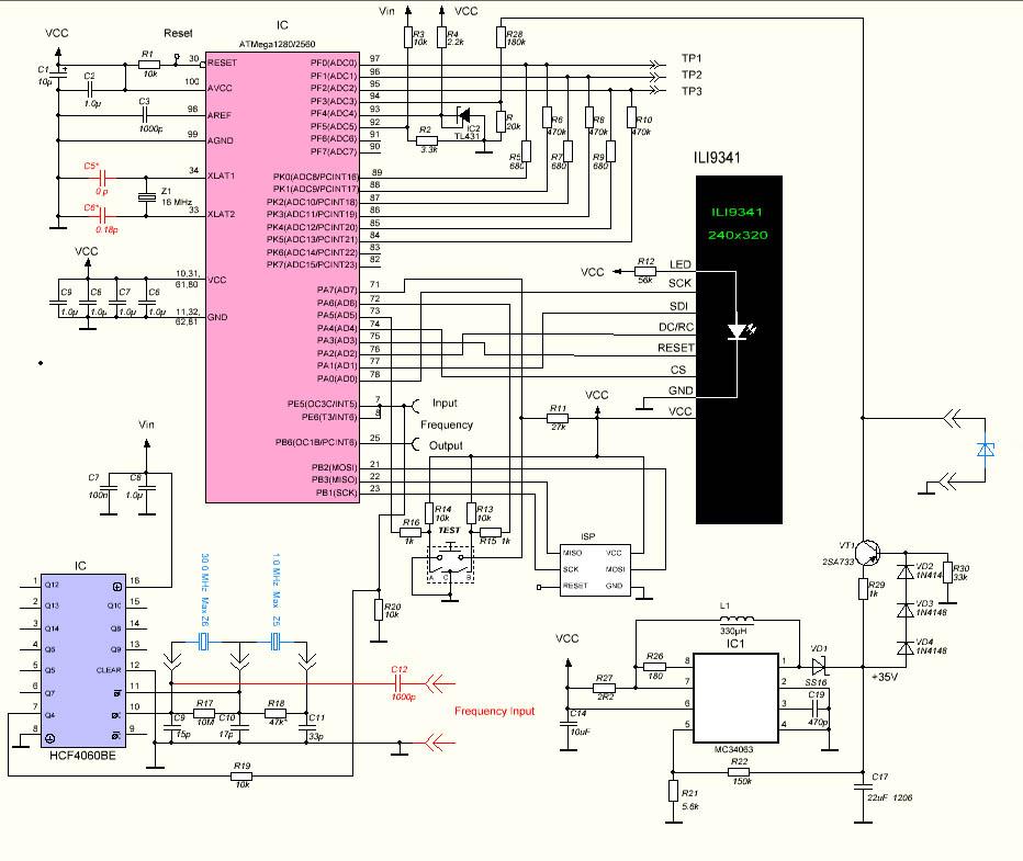
Schaltplan mit ATmega128 und ILI9341 Display
IC ATmega128GZ2560 VCC Reset R1 10k Reset PF0(ADC7) 97 PF1(ADC6) 95 PF2(ADC5) 93 PF3(ADC4) 92 PF4(ADC3) 90 PF5(ADC2) 89 PF6(ADC1) 87 PF7(ADC0) 85 PK0(ADC7/PCINT0) 83 PK1(ADC6/PCINT1) 81 PK2(ADC5/PCINT2) 79 PK3
in „AVR Transistortester MEGA2560 Shield“ · Markt · · Schaltpläne
-
PDF
atmega2560_2561.pdf
bit PWM Channels Flash – Six/Twelve PWM Channels with Programmable Resolution from 2 to 16 Bits (ATmega1281/2561, ATmega640/1280/2560) – 8/16-channel, 10-bit ADC (ATmega1281/2561, ATmega640/1280/2560) – Two/Four Programmable Serial USART (ATmega1281/2561,ATmega640/1280/2560) ATmega640/V – Master/Slave
in „Ethernet Buchse“ · Mikrocontroller und Digitale Elektronik ·
-
Datei
Atmega2560_ADC.c
#define F_CPU 16000000 // CPU clock in Hz #include <avr/io.h> #include <avr/interrupt.h> #define ANALOG_OFF ADCSRA=0 #define ANALOG_ON ADCSRA=(1<<ADEN)|(1<<ADSC)|(1<<ADATE)|(1<<ADPS2)|(1<<ADPS1)|(1<<ADPS0)|(1<<ADIE); #define ADC_CHANNELS 16UL volatile unsigned char channel = 0; volatile uint16_t adc_value[ADC_CHANNELS+1]; int main(void) { ADC_Init(); sei(); while (1) { ; } } void ADC_Init(void) { ADMUX = (1<<REFS0); //Free Running Mode, Division Factor 128, Interrupt on ADCSRA=(1<<ADEN)|(1<<ADSC)|(1<<ADATE)|(1<<ADPS2)|(1<<ADPS1)|(1<<ADPS0)|(1<<ADIE); } ISR (ADC_vect) { ANALOG_OFF; adc_value[channel+
in „Atmega2560 16 ADCs als Interrups "einsammeln"“ · Mikrocontroller und Digitale Elektronik ·
-
Datei
boards.txt
mega.build.variant=mega # default board may be overridden by the cpu menu mega.build.board=AVR_MEGA2560 ## Arduino/Genuino Mega w/ ATmega2560 ## ------------------------- mega.menu.cpu.atmega2560=ATmega2560 (Mega 2560) mega.menu.cpu.atmega2560.upload.protocol=wiring mega.menu.cpu.atmega2560.upload.maximum_size
in „Arduino 1.8.1 & ATmega168PA“ · Mikrocontroller und Digitale Elektronik ·
-
Datei
arduino_verbose_dump.txt
ffunction-sections -fdata-sections -fno-threadsafe-statics -Wno-error=narrowing -MMD -flto -mmcu=atmega2560 -DF_CPU=16000000L -DARDUINO=10819 -DARDUINO_AVR_MEGA2560 -DARDUINO_ARCH_AVR "-IC:\\Users\\xxXXxxXXxx\\AppData\\Local\\Arduino15\\packages\\arduino\\hardware\\avr\\1.8.4\\cores\\arduino" "-IC:\\
in „Arduino Mega2560 mit externem RAM: linker flag für .data section geht nicht“ · Mikrocontroller und Digitale Elektronik ·
-
Datei
Beispiel_1_struct.txt
enc.rel); } void loop (void) { } [/c] [code] Arduino: 1.8.19 (Windows 10), Board: "Arduino Mega or Mega 2560, ATmega2560 (Mega 2560)" "C:\\avrToolchain\\avr-gcc-12.2.0_binutils2.39_avrLibc2.1GitHub/bin/avr-g++" -c -g -Os -w -std=gnu++20 -fno-exceptions -fpermissive -ffunction-sections -fdata-sections -fno-threadsafe-statics -Wno-error=narrowing -flto -Wno-volatile -w -x c++ -E -CC -mmcu=atmega2560 -DF_CPU=16000000L -DARDUINO=10819 -DARDUINO_AVR_MEGA2560 -DARDUINO_ARCH_AVR -fno-sized-deallocation -Wall -Wextra "-IC:\\Arduino IDE Portable\\Mega2560\\arduino-1.8.19\\portable\\packages\\arduino
in „Was ist mit dem avr-gcc 12.x passiert? Internal Compiler Errors“ · Mikrocontroller und Digitale Elektronik ·
-
Datei
Beispiel_2.txt
(prozent); delay (1000); } [/c] [code] Arduino: 1.8.19 (Windows 10), Board: "Arduino Mega or Mega 2560, ATmega2560 (Mega 2560)" "C:\\avrToolchain\\avr-gcc-12.2.0_binutils2.39_avrLibc2.1GitHub/bin/avr-g++" -c -g -Os -w -std=gnu++20 -fno-exceptions -fpermissive -ffunction-sections -fdata-sections -fno-threadsafe-statics -Wno-error=narrowing -flto -Wno-volatile -w -x c++ -E -CC -mmcu=atmega2560 -DF_CPU=16000000L -DARDUINO=10819 -DARDUINO_AVR_MEGA2560 -DARDUINO_ARCH_AVR -fno-sized-deallocation -Wall -Wextra "-IC:\\Arduino IDE Portable\\Mega2560\\arduino-1.8.19\\portable\\packages\\arduino
in „Was ist mit dem avr-gcc 12.x passiert? Internal Compiler Errors“ · Mikrocontroller und Digitale Elektronik ·
-
PDF
Datasheet_ATmega1281_doc2549.pdf
bit PWM Channels Flash – Six/Twelve PWM Channels with Programmable Resolution from 2 to 16 Bits (ATmega1281/2561, ATmega640/1280/2560) – Output Compare Modulator – 8/16-channel, 10-bit ADC (ATmega1281/2561, ATmega640/1280/2560) – Two/Four Programmable Serial USART (ATmega1281/2561,ATmega640/1280/2560
in „LM73 über TWI/I2C mit Atmega1281 auslesen“ · Mikrocontroller und Digitale Elektronik ·
-
Datei
hooks_Error.txt
IDE Portable\Mega2560\arduino-1.8.19\portable\packages\arduino\hardware\avr\1.8.6\variants\mega' '-o' 'C:\avrToolchain\BugTestReportOrdner\Klassen\hooks.c.o' '-mdouble=32' '-mlong-double=64' '-specs=device-specs/specs-atmega2560
in „Was ist mit dem avr-gcc 12.x passiert? Internal Compiler Errors“ · Mikrocontroller und Digitale Elektronik ·
-
Datei
ld8kdemo_build_output.txt
-I"D:\riedl\mikrocontroller_demo\trunk\include" -I"D:\riedl\mikrocontroller_demo\trunk\." -mmcu=atmega2560 -mmcu=atmega2560 -Wall -std=gnu99 -gdwarf-2 -DF_CPU=16 000000UL -O0 -funsigned-char -funsigned-bitfields -fpack-struct -fshort-enums -MD -MP -MT xram.o -MF dep/xram.o.d -x assembler-with-cpp -Wa
in „.data-Segment größer als 8KB möglich“ · Mikrocontroller und Digitale Elektronik ·
-
Datei
AFMotorcpp.txt
defined(__AVR_ATmega1280__) || defined(__AVR_ATmega2560__) // on arduino mega, pin 11 is now PB5 (OC1A) OCR1A = s; #else #error "This chip is not supported!" #endif } inline void initPWM2(uint8_t freq) { #if defined(__
in „Arduino 2560 PWM Frequenz ändern auf 100Hz“ · Mikrocontroller und Digitale Elektronik ·
-
Datei
TimerPrescalersSorted.txt
: <TIMER0> ATmega2560.xml:14808: <TIMER1> ATmega2560.xml:14828: <Prescaler>1:8:64:256:1024</Prescaler> ATmega2560.xml:14832: <TIMER2> ATmega2560.xml:14841: <Prescaler>1:8:64:256:1024</Prescaler> ATmega2560.xml:14863: <Prescaler>1:8:64:256:1024</Prescaler> ATmega2560.xml:14887: <Prescaler>1:8:64:256:1024</Prescaler> ATmega2560.xml:14911: <Prescaler>1:8:64:256:1024</Prescaler> ATmega2560.xml:5: <CORE_VERSION>V3</CORE_VERSION> ATmega2561.xml:13197: <TIMER0> ATmega2561
in „Timer Vorteiler Werte Definition“ · Mikrocontroller und Digitale Elektronik ·
-
Datei
IRremoteInt.h
#if defined(CORE_OC2B_PIN) #define TIMER_PWM_PIN CORE_OC2B_PIN /* Teensy */ #elif defined(__AVR_ATmega1280__) || defined(__AVR_ATmega2560__) #define TIMER_PWM_PIN 9 /* Arduino Mega */ #elif defined(__AVR_ATmega644P__) || defined(__AVR_ATmega644__) #define TIMER_PWM_PIN 14 /* Sanguino */ #else #define
in „IR library auf Atmega328 8Mhz“ · Mikrocontroller und Digitale Elektronik ·
-
Datei
Bemerkungen.txt
>>: avrdude -C "D:\Dude\avrdude.conf" -u -c usbasp-clone -P usb -b 19200 -p m8 Detected 1e9801 = ATmega2560 -----------------------------------------Ende--------------------------- Danach ----------------------- Flash auslesen (1. Lauf als BIN)----------------- >>>: avrdude -C "D:\Dude\avrdude.conf"
in „Arduino Mega 2560 Pro Mini - Arduino des Grauens!“ · Mikrocontroller und Digitale Elektronik ·
-
PDF
Arduino_-_PinMapping2560.pdf
ATmega2560-Arduino Pin Mapping Below is the pin mapping for the Atmega2560. The chip used in Arduino 2560. There are pin mappings to Atmega8 (//www.arduino.cc/en/Hacking/PinMapping) and Atmega 168/328 (//
in „3D Drucker zum Laserengraver umbauen?“ · Mechanik, Gehäuse, Werkzeug ·
-
Datei
Timer1_25kHz.ino
OCR1B 0 */ void loop(void) { } void initPwmPin (const uint8_t pin) { switch(pin) { #if defined(__AVR_ATmega328P__) case 9: TCCR1A |= _BV(COM1A1); pinMode(pin, OUTPUT); break; // UNO Pin 9 case 10: TCCR1A |= _BV(COM1B1); pinMode(pin, OUTPUT); break; // UNO Pin 10 #endif #if defined(__AVR_ATmega2560__) case
in „AVR Timer1 Capture und Overflow gleichzeitig“ · Mikrocontroller und Digitale Elektronik ·
-
PDF
RN-Mega_Board.pdf
Wir denken die Leistungsdaten und Features werden jeden überzeugen! Anleitung vom 5.2.2007 RN-Mega2560Modul von robotikhardware.de Seite 2 von 40 Als hier die Leistungsmerkmale des Controllers und Moduls auf einen Blick: • Leistungsstarker Controller ATMega2560 (eine rder wohl leistungsfähigsten AVR-Controller
in „ATmega2560 spinnt“ · Mikrocontroller und Digitale Elektronik ·
-
Datei
cpu_map.h
--------------------------------------------------------------------------------- #ifdef CPU_MAP_ATMEGA2560 // (Arduino Mega 2560) Working @EliteEng // Serial port pins #define SERIAL_RX USART0_RX_vect #define SERIAL_UDRE USART0_UDRE_vect // Increase Buffers to make use of extra SRAM //#define RX_BUFFER_SIZE
in „Projekt: SerialComCNC Serielles Frontend für CNC GRBL mit ATMega“ · Projekte & Code ·
-
 Bild
Bild
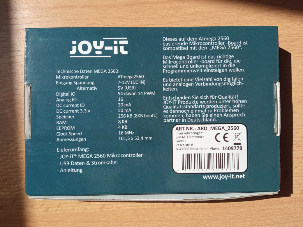
Rückseite einer JOY-IT Mega 2560 Verpackung
JOY-IT Dieses auf dem ATmega 2560 basierende Mikrocontroller-Board ist kompatibel mit den „MEGA 2560". Das Mega Board ist das richtige Mikrocontroller-board für die, die schnell und unkompliziert in die Programmierwelt einsteigen
in „[V] Joy-it ARD Mega2560R3, neu in OVP“ · Markt · · Fotos
-
PDF
ATMEGA2560_PRO_EMBED_SCHEMATIC.pdf
1 2 3 4 5 6 7 8 GND +5V M8RXD R2 D1 J1 U1 R3 D48 MOSI 1 16 RESET D49 1 4 SCK A F1 M8TXD 2 GND VCC 15 MISO 2 5 SS A +5V TXD RS232 C1 3 6 USB1 M8RXD 3 RXD RTS 14 R4 GND 4 V3 DTR 13 DTR M8TXD D0 C2 RD+ 5 12 R5 RD- RD- 6 UD+ DCD 11 1 C3 7 UD- RI 10 2 8 XI DSR 9 3 XO CTS 4 RD+ D43 R7 +5V SCL 5 R6 R8 J2 GND Y1 C5 AREF GND RESET 2 D44 R9 1 +5V SDA C4 GND VIN +5V R10 J3 U2 +5V U3 3.3V +5V +5V +5V M8RXD VIN D1 +5V 1 2 3 12 3 12 3 4 C10 C15 C9 C6 C7 C8 LED1 5 6 7 8 C11 3.3V GND B GND GND GND R11 M8TXD B GND +5V LED2 J4 +5V 1 4 MISO MOSI SCK GND 2 5 RESET R12 3 6 +5V GND LED3 GND GND +5V +5V +5V E 0 1 2 3
in „RC Modellbau: Mikrocontroller und Motorstörungen“ · Analoge Elektronik und Schaltungstechnik ·
-
Datei
out.c
******************************************************** // File........: out.c // Target(s)...: Atmega328p, Atmega2560, Atmega32u2, Atmega32u4 // Compiler....: AVR-GCC // Description.: routines for output USART/LCD/SRAM/USB // outc -> Zeichen ausgeben // outs -> String ausgeben // out_u16bin -> binaere
in „Atmega32U4-Board: USB-Ausgabe in Betrieb nehmen“ · Mikrocontroller und Digitale Elektronik ·
-
Datei
out.c
******************************************************** // File........: out.c // Target(s)...: Atmega328p, Atmega2560, Atmega32u2, Atmega32u4 // Compiler....: AVR-GCC // Description.: routines for output USART/LCD/SRAM/USB // outc -> Zeichen ausgeben // outs -> String aus SRAM ausgeben // outs_p ->
in „Atmega32U4-Board: USB-Ausgabe in Betrieb nehmen“ · Mikrocontroller und Digitale Elektronik ·
-
Datei
main.h
Flämig on 22.08.10. * Copyright 2010 __MyCompanyName__. All rights reserved. * */ #ifndef __AVR_ATmega2560__ #define __AVR_ATmega2560__ #include <avr/io.h> #include <util/delay.h> #include <avr/interrupt.h> #define bitand & #define bitor | #define toggle ^ #define and && #define or || #define BIT0 1
in „[AVR] (ext) Interrupt aktivieren?“ · Mikrocontroller und Digitale Elektronik ·
-
Datei
ePaper-Test2.ino
BUSY -> 7, RST -> 9, DC -> 8, CS-> 10, CLK -> 13, DIN -> 11 // Board: "Arduino Nano" // Processor: "ATmega328P (Old Bootloader)" // Programmer: "AVRISP mkII" // Anschluss und Einstellungen für Arduino MEGA 2560: // BUSY -> 7, RST -> 9, DC -> 8, CS-> 53, CLK -> 52, DIN -> 51 // Board: "Arduino/Genuino Mega or Mega 2560" // Processor: "ATmega2560 (Mega 2560)" // Programmer: "AVRISP mkII" // include library, include base class, make path known #include <GxEPD.h> #include <GxGDEH029A1/GxGDEH029A1.h> // 2.9" b/w #include
in „Arduino-Library auf GitHub: Keine Dokumentation?“ · Mikrocontroller und Digitale Elektronik ·
-
Datei
log2.txt
http://www.bdmicro.com/ Copyright (c) 2007-2009 Joerg Wunsch System wide configuration file is "C:\2560\avrdude.conf" Using Port : COM4 Using Programmer : stk500v2 Overriding Baud Rate : 19200 AVR Part : ATMEGA2560 Chip Erase delay : 9000 us PAGEL : PD7 BS2 : PA0 RESET disposition : dedicated RETRY pulse
in „Bootloader mega2560“ · Mikrocontroller und Digitale Elektronik ·
-
Datei
Bosch_Athlet_DIY_v0_1.ino
(lena_s) this piece of code to awaken this vaccuumclears again. */ // SET your Board to MiniCore ATmega328PB @ 8Mhz Internal, BOD=2.7V, no Bootloader #include <Arduino.h> #include <Wire.h> //settings for 25.2V-Gerät BCH6L2560 by lena_s (brush on only on Switch pos turbo; higer Vac but less runtime) String TYPE = "BCH6L2560"; #define VAC_PWM_LOW 100 // for BCH6L2560: PWM vac-motor for switch-level LOW #define VAC_PWM_MID 200 // for BCH6L2560: PWM vac-motor for switch-level MID #define VAC_PWM_HIGH 200 // for BCH6L2560:
in „Bosch Athlet 25,2 V Akku 7 Stück Tauschen“ · Analoge Elektronik und Schaltungstechnik ·
-
Datei
log1.txt
http://www.bdmicro.com/ Copyright (c) 2007-2009 Joerg Wunsch System wide configuration file is "C:\2560\avrdude.conf" Using Port : COM4 Using Programmer : stk500v2 Overriding Baud Rate : 115200 AVR Part : ATMEGA2560 Chip Erase delay : 9000 us PAGEL : PD7 BS2 : PA0 RESET disposition : dedicated RETRY pulse
in „Bootloader mega2560“ · Mikrocontroller und Digitale Elektronik ·
-
Datei
Bosch_Athlet_DIY_240619.ino
(lena_s) this piece of code to awaken this vaccuumclears again. */ // SET your Board to MiniCore ATmega328PB @ 8Mhz Internal, BOD=2.7V, no Bootloader // https://github.com/MCUdude/MiniCore#how-to-install #include <Wire.h> #define SWVERSION 240619 /* //values for 25.2V-model BCH6L2560: #define TYPE "BCH6L2560
in „Bosch Athlet 25,2 V Akku 7 Stück Tauschen“ · Analoge Elektronik und Schaltungstechnik ·
-
Datei
Athlet_V1_4_32_4.ino
(lena_s) this piece of code to awaken this vaccuumclears again. */ // SET your Board to MiniCore ATmega328PB @ 8Mhz Internal, BOD=2.7V, no Bootloader // https://github.com/MCUdude/MiniCore#how-to-install #include <Wire.h> #define SWVERSION 240619 /* //values for 25.2V-model BCH6L2560: #define TYPE "BCH6L2560
in „Bosch Athlet 25,2 V Akku 7 Stück Tauschen“ · Analoge Elektronik und Schaltungstechnik ·
-
PDF
ATT5FCA9.pdf
STK502 AT90USB646 STK525 ATtiny45 ATmega8 ATmega165 STK502 ATmega2560 STK503 AT90USB647 STK525 ATtiny84 ATmega16 ATmega165P STK502 ATmega2561 STK501 AT90USB1286 STK525 ATtiny85 ATmega32 ATmega168 ATmega3250 STK504 AT90USB1287 STK525 STK501
in „Angebot STK500+STK501+JTAGICE“ · Mikrocontroller und Digitale Elektronik ·
-
Datei
wiring.c
sbi(TCCR4C, PWM4D); // enable PWM mode for comparator OCR4D #else /* beginning of timer4 block for ATMEGA1280 and ATMEGA2560 */ #if defined(TCCR4B) && defined(CS41) && defined(WGM40) sbi(TCCR4B, CS41); // set timer 4 prescale factor to 64 sbi(TCCR4B, CS40); sbi(TCCR4A, WGM40); // put timer 4 in 8-bit phase correct pwm mode #endif #endif /* end timer4 block for ATMEGA1280/2560 and similar */ #if defined(TCCR5B) && defined(CS51) && defined(WGM50) sbi(TCCR5B, CS51); // set timer 5 prescale factor to 64 sbi(TCCR5B, CS50); sbi(TCCR5A, WGM50); // put timer 5 in 8-bit
in „IRMP - Infrared Multi Protocol Decoder“ · Projekte & Code ·
-
PDF
avr-libc-user-manual-1.8.0.pdf
, ATmega1280, ATmega1281, - T_vect CAPTURE4 Capture Event ATmega2560, ATmega2561 TIMER4_CO- SIG_OUTPU- Timer/Counter4 - ATmega640, ATmega1280, ATmega1281, - MPA_vect T_COMPAR- Compare Match - ATmega2560, ATmega2561
in „Interrupt Probleme beim Arduino“ · Mikrocontroller und Digitale Elektronik ·
-
Datei
out_of_range_build_output.txt
avr-gcc -mmcu=atmega2560 -Wl,-section-start=.data=0x802200,--defsym=__heap_end=0x80ffff -v -Wl,--script=morepgmavr6.x -Wl,-Map=eclcpu.map [....] -L"C:\avrgcc\lib" -L"D:\riedl\eclcpu\trunk" -o eclcpu.elf Using built-in
in „.data-Segment größer als 8KB möglich“ · Mikrocontroller und Digitale Elektronik ·
-
Datei
mit_-lm.txt
avr-gcc -Wl,-Map,TRENDvent_Bedien.map -T c:/programme/winavr/avr/lib/ldscripts/TRENDvent.x -lm -mmcu=atmega2560 -o"TRENDvent_Bedien.elf" ./Code/boot.o ./Code/dateisystem.o ./Code/doxygen.o ./Code/key.o ./Code/lcd_graph.o ./Code/lcd_text.o ./Code/main.o ./Code/memory.o ./Code/menue.o ./Code/spi.o ./Code/sprache.o
in „warning: internal error: out of range error“ · Mikrocontroller und Digitale Elektronik ·
-
Datei
ohne_-lm.txt
avr-gcc -Wl,-Map,TRENDvent_Bedien.map -T c:/programme/winavr/avr/lib/ldscripts/TRENDvent.x -mmcu=atmega2560 -o"TRENDvent_Bedien.elf" ./Code/boot.o ./Code/dateisystem.o ./Code/doxygen.o ./Code/key.o ./Code/lcd_graph.o ./Code/lcd_text.o ./Code/main.o ./Code/memory.o ./Code/menue.o ./Code/spi.o ./Code/sprache.o
in „warning: internal error: out of range error“ · Mikrocontroller und Digitale Elektronik ·
-
Datei
platformio.ini
common_avr8] board_build.f_cpu = 16000000L src_filter = ${common.default_src_filter} +<src/HAL/AVR> # # ATmega2560 # [env:mega2560] platform = atmelavr extends = common_avr8 board = megaatmega2560 # # ATmega2560 with extended pins 70-85 defined # BOARD_BQ_ZUM_MEGA_3D # BOARD_ULTIMAIN_2 # BOARD_MIGHTYBOARD_REVE
in „Ender3 Z-Achse fährt mit Marlin nur nach oben“ · Mechanik, Gehäuse, Werkzeug ·
-
Datei
Bosch_Athlet_DIY_240416.ino
(lena_s) this piece of code to awaken this vaccuumclears again. */ // SET your Board to MiniCore ATmega328PB @ 8Mhz Internal, BOD=2.7V, no Bootloader // https://github.com/MCUdude/MiniCore#how-to-install #include <Wire.h> #define SWVERSION 240416 //values for 25.2V-model BCH6L2560: #define TYPE "BCH6L2560
in „Bosch Athlet 25,2 V Akku 7 Stück Tauschen“ · Analoge Elektronik und Schaltungstechnik ·
-
Datei
wiring.c
sbi(TCCR4C, PWM4D); // enable PWM mode for comparator OCR4D #else /* beginning of timer4 block for ATMEGA1280 and ATMEGA2560 */ #if defined(TCCR4B) && defined(CS41) && defined(WGM40) sbi(TCCR4B, CS41); // set timer 4 prescale factor to 64 sbi(TCCR4B, CS40); sbi(TCCR4A, WGM40); // put timer 4 in 8-bit phase correct pwm mode #endif #endif /* end timer4 block for ATMEGA1280/2560 and similar */ #if defined(TCCR5B) && defined(CS51) && defined(WGM50) sbi(TCCR5B, CS51); // set timer 5 prescale factor to 64 sbi(TCCR5B, CS50); sbi(TCCR5A, WGM50); // put timer 5 in 8-bit
in „Sekunden,Minuten zählen mit der Funktion Millis()“ · Mikrocontroller und Digitale Elektronik ·
-
Datei
x.txt
atmega168 atmega168a atmega168p atmega168pa atmega169 atmega169a atmega169p atmega169pa atmega16a atmega16hva atmega16hva2 atmega16hvb atmega16hvbrevb atmega16m1 atmega16u2 atmega16u4 atmega2560 atmega2561
in „Eclipse (mars) und AVR -- Fehlermeldungen“ · Mikrocontroller und Digitale Elektronik ·
-
Datei
HardwareSerial.h
----chanced------------------------------------- extern HardwareSerial Serial; #if defined(__AVR_ATmega1280__) || defined(__AVR_ATmega2560__) extern HardwareSerial Serial1; extern HardwareSerial Serial2; extern HardwareSerial Serial3; #endif */ //#endif extern HardwareSerial HWSerial; #if defined(__AVR_ATmega1280__) || defined(__AVR_ATmega2560__) extern HardwareSerial HWSerial1; extern HardwareSerial HWSerial2; extern HardwareSerial HWSerial3; #endif
in „Arduino + GSM-GPRS-GPS-Shield“ · Mikrocontroller und Digitale Elektronik ·
-
Datei
test9_readme.txt
0x2E000 verlegt) Code wie 02 Terminal-Modus von avrdude zeigt auch den Code bei 0x2e000 avrdude -p atmega2560 -c stk500v2 -P /dev/ttyUSB0 -t dump flash 0x2e000 32 --- 04: funktioniert (vor der Schleife ein rjmp) 0003e000 <__ctors_end>: 3e000: 27 9a sbi 0x04, 7 ; 4 3e002: 00 00 nop 3e004: 00 00 nop 3e006
in „Programmierfehler bei 0x3E000 im ATmega2560, wenn mySmartUSBlight per ISP verwendet“ · Mikrocontroller und Digitale Elektronik ·
-
PDF
Arduino.pdf
// set the reference to Vcc and the measurement to the internal 1.1V reference #if defined(__AVR_ATmega32U4__) || defined(__AVR_ATmega1280__) || defined(__AVR_ATmega2560__) ADMUX = _BV(REFS0) | _BV(MUX4) | _BV(MUX3) | _BV(MUX2) | _BV(MUX1); #elif defined (__AVR_ATtiny24__) || defined(__AVR_ATtiny44__
in „Aref Spannung, was ist besser?“ · Mikrocontroller und Digitale Elektronik ·
-
Datei
Sd2PinMap.h
------------------------------------------------------------------------------ #if defined(__AVR_ATmega1280__) || defined(__AVR_ATmega2560__) // Mega // Two Wire (aka I2C) ports uint8_t const SDA_PIN = 20; uint8_t const SCL_PIN = 21; // SPI port uint8_t const SS_PIN = 53; uint8_t const MOSI_PIN = 51;
in „SD Karte an AVR 328 Arduino UNO welche Pins ?“ · Mikrocontroller und Digitale Elektronik ·
-
Datei
Label.inc
Vertikal 2-Bit-Abwaertszaehler Bit1 .DEF tfl = r6 ;Taster FLaggen .EQU tap = $0C ;TApin => PIN E des ATmega 2560 .EQU KEY_PORT = $0E ; PORT E des ATmega 2560 .EQU alltast = $03 ;Tastereingaenge Maske
in „Universelle Tastenabfrage nach PeDa in AVR Assembler“ · Mikrocontroller und Digitale Elektronik ·