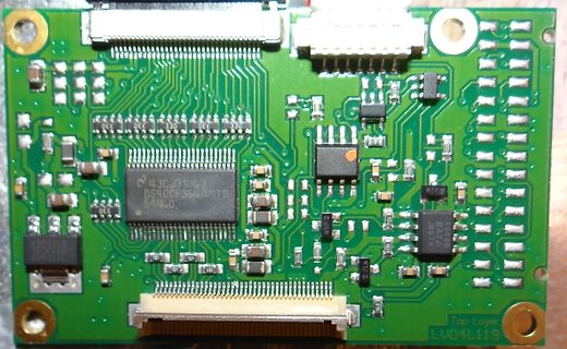
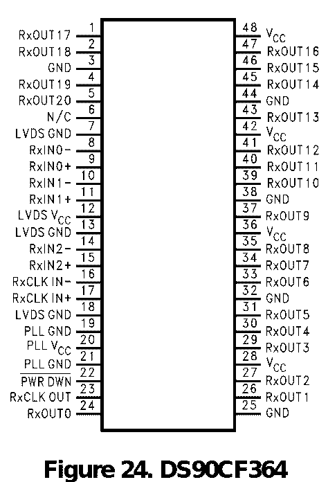
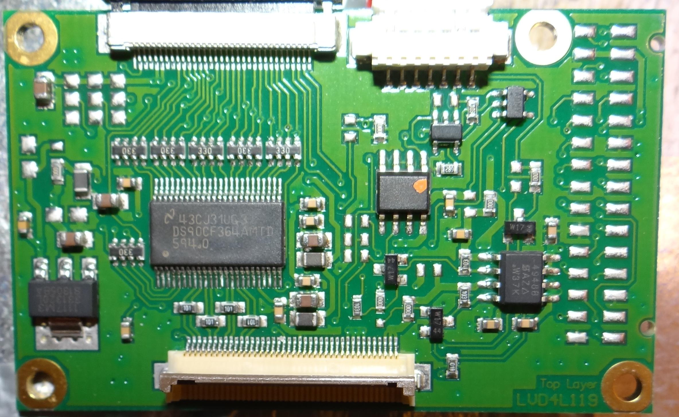
muss ein 32-poliges Flexkabel sein. > Dieses geht in ein Interfaceboard, was auf 40-Pin (mit einem DS90CF364) > konvertiert. Über eine 2 x 20 Pin Steckverbindung wird dann das > Messgerät angeschlossen, was mit einem 40-Pin Flachbandkabel verbunden > wird. Hier ist schon mal das DB des DS90Cf364 https://www.ti.com/lit/ds/symlink/ds90cf364.pdf
beispielsweise von TI oder National oder Thine hergestellt. Ein Beispiel ist http://www.national.com/pf/DS/DS90CF366.html Bist Du Dir sicher damit, daß Dein PC-Board eine LVDS-Schnittstelle hat? Die beliebten VIA EPIA-Boards haben zwar einen Stecker, von dem behauptet wird, daß das eine LVDS-Schnittstelle
Den DS90CF364 gibts von RS-Components und Farnell http://www.national.com/ds/DS/DS90CF364.pdf DS90C363/DS90CF364 +3.3V Programmable LVDS Transmitter 18-Bit Flat Panel Display (FPD) Link 65 MHz, +3.3V
mit dem genannten Tranceiver wird das denke wunderbar. Als Receiver brauche ich dann demnach einen DS90CF364A. Oder ehr nicht, weil der mit der Datenrate nicht fertig wird. Es sei denn, die angegebenen 65MHz sind nicht äußerstes Limit. DS90CF366 geht bis 85MHz, auch noch nicht ausreichend. DS90CF388A
Soweit ich deine geforderten Datenraten verstehe, müsste es mit dem DS90CF288A als Receiver klappen. Er erreicht 112MHz pixel clock. Du benutzt seine Eingänge A0, A1 und A2. Die Ausgänge verteilst du passend auf die Eingänge des DS90C387A und hast einen Konverter wie oben
aufgrund ihrer Industrietauglichkeit bei uns gesetzt... MIPI DSI auf LVDS habe ich gefunden (TI SN65DS185) aber primitives parallel RGB ist mir nicht untergekommen... Ich wäre für eine Lösung dankbar. (Und ja, FPGA mit passender IP geht auch... ich hätte aber gerne einen Chip...)
nicht sonderlich teuer. Als "Bridge" würde ich das auch nicht bezeichnen. http://www.ti.com/product/DS90CF364 http://www.ti.com/product/DS90CF364 für 18- und 24-Bit-Displays.
kann, aber wie kommt man von TTL wieder auf USB oder ähnliches? https://www.ti.com/product/de-de/DS90CF364 Pinbelegung vom BMW LVDS-Stecker 1 -> LVDS Channel 2+ 2 -> LVDS Channel 2- 3 -> -- 4 -> LVDS Channel 1+ 5 -> LVDS Channel 1- 6 -> LVDS clock + 7 -> LCDS clock - 8 -
restlichen 6 dann die jeweilige Farbe. Aber der minimale Takt ist ein Problem, der vom TO vorgeschlagene DS90CF364 geht bissl weiter runter, vielleicht koennte der das grad' ab - muesste man halt mal den Takt messen - aber selbst wenn: das hilft ja nicht so wirklich weiter. Denn dann haste 'nen breiten
also ich hab jetzt versucht den zweiten knoten auf meinem dsPICDem 28 zu realisieren, scheitere aber da noch an der mangelnden Beschreibung zu dem Board. Die Register für den Can bleiben bei einem dsPIC30F4012 gleich wie beim 6014, aber die portinitialisierung
EIA-364-65 connector unmated 3.3.1 CF/CF+ Card Connector The socket-connector shall be located in the CF/CF+ Card as shown in Figure 3 and Figure 4. The CF/CF+ Card socket-connector interface layout shall match
with EIA-364-65 connector unmated 3.3.1 CF/CF+ Card Connector The socket-connector shall be located in the CF/CF+ Card as shown in Figure 3 and Figure 4. The CF/CF+ Card socket-connector interface layout shall match
...nein, Du brauchst bloss z.B. einen DS90CF364A von National (und die Abschlusswiderstände für die LVDS-Paare nicht vergessen!), dann hast Du wieder TTL Signale. Dem Kontron-Board musst Du dann noch beibiegen (BIOS Einstellung oder JILI),
; ΔLED-PP 50mA The chosen components from step 1 are: Δv = 1V IN-PP VTURN-ON= 10V; HYS= 1.1V η = 0.90 1. NOMINAL SWITCHING FREQUENCY Assume COFF= 470pF and η = 0.90. Solve OFF R 2. INDUCTOR RIPPLE CURRENT Solve for L1: The closest standard inductor value is 22 µH therefore the actual L-PPis: The chosen
Refer to the MPASM User's Guide for additional information on * ; features of the assembler (Document DS33014). * ; * ; Refer to the respective PIC data sheet for additional * ; information on the instruction set. * ; * ;********************************************************************** ; * ; Filename
Refer to the MPASM User's Guide for additional information on * ; features of the assembler (Document DS33014). * ; * ; Refer to the respective PIC data sheet for additional * ; information on the instruction set. * ; * ;********************************************************************** ; * ; Filename
Refer to the MPASM User's Guide for additional information on * ; features of the assembler (Document DS33014). * ; * ; Refer to the respective PIC data sheet for additional * ; information on the instruction set. * ; * ;********************************************************************** ; * ; Filename
components from step 1 are: ΔiL-PP= 450mA; Δi LED-PP= 50mA Δv = 1V IN-PP VTURN-ON = 10V; VHYS = 1.1V η = 0.90 1. NOMINAL SWITCHING FREQUENCY 2. INDUCTOR RIPPLE CURRENT Assume C OFF= 470pF and η = 0.90. Solve for OFF: Solve for L1: The closest standard inductor value is 22 µH therefore the actual ΔL-PPis: The
und da Musik aus dem Radio.. sixteen horsepower sinnerman https://www.youtube.com/watch?v=GlFP2CBOhDs&list=RD2e3vLaHt7yY&index=8 Mari Boine - Vuoi Vuoi Mu (Vuoi Vuoi Me) https://www.youtube.com/watch?v=NyB90aNkURU Blackmore’s Night—Temple of the King (dedicated to Ronnie James Dio)—Phoenixville
Y Y NC 14 F F F 0.01 SW C C R CF88 12 12 15 GND CF99 4 3 2 110/50V D D load(0) V C 6 V C 6 GND D B RF73 0 D B RF73 0 5 E - 9 8 7 6 5 4 3 2 1 8 8 - F D T T 9 CF60 Dummy CF60 Dummy S J V U - J D D D S S S CF59 Dummy +24V CF59 Dummy +24V
SD Karte mit ext2 zu Mounten klapt so weit > was für ein USB Module brauche ich noch um auch eine CF Karte mounten zu > können ? Bei mir funzt CF mit einem CF2USB Adapter genauso wie ein USB Stick. Evtl stimmt was mit der PArtitionierung oder Formatierung der CF nicht.
IDAPython an. Ich weiß aber nicht, ob die Freeware auch IDAPython macht. http://www.hexblog.com/?p=90
temperature range: -40°C to +105°C ranging from 2.3V to 6.0V in increments of 0.1V. ●Package SSOP5: 2.90mm x 2.80mm x 1.25mm ●Features ▯ High accuracy detection SSOP3: 2.92mm x 2.80mm x 1.25mm ▯ Ultra-low current consumption ▯ Two output types (Nch open drain and CMOS output) VSOF5: 1.60 mm x 1.60mm x 0.60mm
und das Wissen das dahinter steckt ... Schon sehr beeindruckend. Leider leider entwickeln sich 90% eines Programms in 10% der Zeit ... Die anderen 10% benötigen dann 90% Zeit. Die zeitaufwändigen Sachen kommen vermutlich erst ... Bug-fixing und Usability ... Das ist dann immer das Stadium, in
Braucht noch Jemand Lochraster-Platinen. Habe hier xxl-Teile ca. 450mm x 120mm und 450mm x 90mm und 310mm x 100mm solange Vorat vorhanden alles weitere per mail dirk
from the battery. But when the test is finished and the Tester just show the result current jumps to 90mA and stay stable for about 15 seconds. After this the Tester turns itself OFF. Any suggestion why this happening?
Controlled Erase and Program Operations–S29GL256N Only Parameter Speed Options JEDEC Std. Description 80 90 90 100 Unit AVAV tWC Write Cycle Time (Note 1) Min 80 90 90 100 ns AVWL AS Address Setup Time Min 0 ns ELAX tAH Address Hold Time Min 45 ns DVEH tDS Data Setup Time Min 45 ns EHDX tDH Data Hold Time
Read as ‘0’ Note: Bit PEIE of the INTCON register must be set to enable any peripheral interrupt. DS40001574D-page 90 2011-2017 Microchip Technology Inc. PIC16(L)F1938/9 REGISTER 7-5: PIR1: PERIPHERAL INTERRUPT REQUEST REGISTER 1 R/W-0/0 R/W-0/0 R-0/0 R-0/0 R/W-0/0 R/W-0/0 R/W-0/0 R/W-0/0 TMR1GIF
a” coeffiient The infinitesimal length of the fluid trajectory can be assessed through (3.69). 2 2 ds = √ dθ + dr (3.69) Wheredθ = w dtθs tangentialcomponentanddr = w dtis therradialcomponent, as shown in Fig. 3.9. When ∑NR ds islowerthantheentranceregionlength,thecoefficientfornotfully i=0 NR developed

 Bild
Bild
 Bild
Bild