-
PDF
Infineon_20176A.pdf
PG-TO220-3 IRFZ46NPBF SP001571842 IRFZ46NPBF PG-TO220-3 IRFZ48NPBF SP001552474 IRFZ48NPBF PG-TO220-3 IRL1004PBF SP001567104 IRL1004PBF PG-TO220-3 IRL1404ZPBF SP001576516 IRL1404ZPBF PG-TO220-3 IRL2505PBF SP001567114 IRL2505PBF PG-TO220-3 IRL2910PBF SP001576496 IRL2910PBF PG-TO220-3 IRL3705NPBF SP001578520 IRL3705NPBF PG-TO220-3 IRL3705ZPBF SP001557992 IRL3705ZPBF PG-TO220-3 IRL3803PBF SP001557982 IRL3803PBF PG-TO220-3 IRL520NPBF SP001558080 IRL520NPBF PG-TO220-3 IRL530NPBF SP001578734 IRL530NPBF PG-TO220
in „Unstimmigkeit bei IRLB4030 Bestellung“ · Analoge Elektronik und Schaltungstechnik ·
-
PDF
IRL3713.pdf
PD-94184D IRL3713 SMPS MOSFET IRL3713S IRL3713L Applications l High Frequency Isolated DC-DC HEXFET Power MOSFET Converters with Synchronous Rectification for Telecom and Industrial Use V DSS R DS(on) max (mW) ID
in „Logic Level Mosfet - Welcher "kann mehr"“ · Analoge Elektronik und Schaltungstechnik ·
-
PDF
Schematic_Sheets.PDF
Q8 1 G D IRL4905 1 G DQ9 R14 4.7k S IRL4905 PIN_30 R13 4.7k S R15 4.7k SIRL4905 PIN_23 Q11 Q10 PIN_37 Q12 3.9k BC547 R17 3 +24V_L3 3.9k BC547 R16 3 3.9k BC547 R18 3 +24V_L17 +24V_L10 4.7k 4.7k 4.7k GND 2 GND GND
in „LED Strips an Treppe mit PWM der Reihe nach Ein/Aus“ · Analoge Elektronik und Schaltungstechnik ·
-
PDF
irl2203ns.pdf
PD - 94394A IRL2203NS IRL2203NL HEXFET Power MOSFET l Advanced Process Technology l Ultra Low On-Resistance D l Dynamic dv/dt Rating V DSS = 30V l 175°C Operating Temperature l Fast Switching R DS(on) = 7.0mΩ l FullyAvalancheRated
in „FETs - 5V steuerspannung - selbstleitend selbstsperrend“ · Analoge Elektronik und Schaltungstechnik ·
-
PDF
irl7833.pdf
PD-94668B IRL7833 IRL7833S IRL7833L ® Applications HEXFET Power MOSFET l High Frequency Synchronous Buck V R max Qg Converters for Computer Processor Power DSS DS(on) l High Frequency Isolated DC-DC 30V 3.8m : 32nC
in „Beschaltung Mosfet für Brushless-Regler“ · Analoge Elektronik und Schaltungstechnik ·
-
PDF
irl540npbf.pdf
PD - 94997 IRL540NPbF HEXFET Power MOSFET Lead-Free www.irf.com 1 2/10/04 IRL540NPbF 2 www.irf.com IRL540NPbF www.irf.com 3 IRL540NPbF 4 www.irf.com IRL540NPbF www.irf.com 5 IRL540NPbF 6 www.irf.com IRL540NPbF www.irf.com 7 IRL540NPbF TO-220AB Package Outline Dimensions are shown in millimeters (inches) 10.54 (.415) 3.78 (.149) - B - 2.87 (.113) 10.29 (.405) 3.54 (.139) 4.69 (.185) 2.62 (.103) - A - 4.20 (.165) 1.32 (.052)
in „N-Channel Mosfet max. Spannung Gate zu Drain“ · Mechanik, Gehäuse, Werkzeug ·
-
PDF
IRL540N.pdf
PD - 94997 IRL540NPbF HEXFET Power MOSFET Lead-Free www.irf.com 1 2/10/04 IRL540NPbF 2 www.irf.com IRL540NPbF www.irf.com 3 IRL540NPbF 4 www.irf.com IRL540NPbF www.irf.com 5 IRL540NPbF 6 www.irf.com IRL540NPbF www.irf.com 7 IRL540NPbF TO-220AB Package Outline Dimensions are shown in millimeters (inches) 10.54 (.415) 3.78 (.149) - B - 2.87 (.113) 10.29 (.405) 3.54 (.139) 4.69 (.185) 2.62 (.103) - A - 4.20 (.165) 1.32 (.052)
in „Umsetzung eines 5V Output mit ESP32 und AQY Halbleiterrelais“ · Mikrocontroller und Digitale Elektronik ·
-
PDF
INFINEON_IRL520NPBF_DB-EN.pdf
PD-95668 IRL520NPbF Lead-Free www.irf.com 1 8/2/04 IRL520NPbF 2 www.irf.com IRL520NPbF www.irf.com 3 IRL520NPbF 4 www.irf.com IRL520NPbF www.irf.com 5 IRL520NPbF 6 www.irf.com IRL520NPbF www.irf.com 7 IRL520NPbF
in „Schaltung mit Arduino Nano RP2040 Connect funktioniert auf Steckbrett, aber nicht gelötet“ · Platinen ·
-
PDF
IRL540N-UMW.pdf
R UMW IRL540N N-Channel Enhancement Mode Power MOSFET Description The UMW IRL540N uses advanced trench technology and design to provide excellenDS(ON)ith low gate charge. It can be used in a wide variety of applications
in „Problem mit Mosfet IRL540 an 52V, öffnet nicht mehr“ · Analoge Elektronik und Schaltungstechnik ·
-
PDF
irl7486mpbf-936689.pdf
DirectFET ISOMETRIC ME Standard Pack Base part number Package Type Orderable Part Number Form Quantity ® IRL7486MPbF DirectFET ME Tape and Reel 4800 IRL7486MTRPbF ) 4.0 220 ( I = 123A 200 c 3.5 D t 180 i e 3.0 A 160 R t 140 O 2.5 r e u 120 u C o 2.0 a 100 - D - TJ= 125°C , 80 a 1.5 ID 60 D ,) TJ= 25°C 40
in „Reparatur Makita XWT08Z (DTW1002Z)“ · Analoge Elektronik und Schaltungstechnik ·
-
Datei
jlink.txt
Hardware: V8.00 S/N: xxxxxxxxxxx OEM: SEGGER-EDU Feature(s): FlashBP, GDB VTarget = 3.261V Info: TotalIRLen = 9, IRPrint = 0x0011 Info: Found Cortex-M4 r0p1, Little endian. Info: TPIU fitted. Info: ETM fitted. Info: FPUnit: 6 code (BP) slots and 2 literal slots Found 2 JTAG devices, Total IRLen = 9: #0 Id: 0x4BA00477, IRLen: 04, IRPrint: 0x1, CoreSight JTAG-DP (ARM) #1 Id: 0x06413041, IRLen: 05, IRPrint: 0x1, STM32 Boundary Scan Cortex-M4 identified. JTAG speed: 100 kHz J-Link>h WARNING: CPU could not be halted J-Link
in „[STM32/Cortex-M4] JTag nur beim Systemflash möglich. Fehler beim Mainflash“ · Mikrocontroller und Digitale Elektronik ·
-
PDF
SH7709.pdf
–IRL0 = 0010 H'240 IRL3–IRL0 = 0011 H'260 IRL3–IRL0 = 0100 H'280 IRL3–IRL0 = 0101 H'2A0 IRL3–IRL0 = 0110 H'2C0 IRL3–IRL0 = 0111 H'2E0 IRL3–IRL0 = 1000 H'300 IRL3–IRL0 = 1001 H'320 IRL3–IRL0 = 1010 H'340
in „HD6417709A F133B“ · Mikrocontroller und Digitale Elektronik ·
-
PDF
IRL540.pdf
IRL540, SiHL540 Vishay Siliconix Power MOSFET FEATURES PRODUCT SUMMARY • Dynamic dV/dt Rating VDS (V) 100 Available • Repetitive Avalanche Rated RDS(on)Ω) V GS= 5.0 V 0.077 RoHS* Q (Max.) (nC) 64 • Logic-Level
in „MOSFET mit Treiber Verständnisproblem“ · Analoge Elektronik und Schaltungstechnik ·
-
PDF
IRL540.pdf
IRL540, SiHL540 Vishay Siliconix Power MOSFET FEATURES PRODUCT SUMMARY • Dynamic dV/dt Rating VDS (V) 100 Available • Repetitive Avalanche Rated RDS(on)Ω) V GS= 5.0 V 0.077 RoHS* Q (Max.) (nC) 64 • Logic-Level
in „Problem mit Mosfet IRL540 an 52V, öffnet nicht mehr“ · Analoge Elektronik und Schaltungstechnik ·
-
PDF
irl630.pdf
PD -9.1255 IRL630 HEXFET Power MOSFET Dynamic dv/dt Rating RepetitiveAvalancheRated Logic-Level Gate Drive V DSS = 200V RDS(ON) Specified at V GS = 4V & 5V 150°C Operating Temperature R DS(on) = 0.40 FastSwitching
in „Kontrolle der Kühlkörperberechnung“ · Mikrocontroller und Digitale Elektronik ·
-
PDF
IRLN540.pdf
PD - 9.1495 IRL540N PRELIMINARY HEXFET Power MOSFET l Logic-Level Gate Drive D l Advanced Process Technology V DSS = 100V l Isolated Package l High Voltage Isolation = 2.5KVRMS R DS(on) = 0.044 l Sink to Lead Creepage
in „HEXFET als Widerstand?“ · Analoge Elektronik und Schaltungstechnik ·
-
PDF
IRL1004.pdf
PD - 91702B IRL1004 HEXFET Power MOSFET l Logic-Level Gate Drive D l Advanced Process Technology VDSS = 40V l Ultra Low On-Resistance l Dynamic dv/dt Rating R DS(on) = 0.0065 l 175°C Operating Temperature G l Fast
in „Mosfet als Schalter 100W“ · Analoge Elektronik und Schaltungstechnik ·
-
PDF
irl3705n.pdf
PD-9.1370C IRL3705N HEXFET Power MOSFET l Logic-Level Gate Drive D l Advanced Process Technology V = 55V DSS l Dynamic dv/dt Rating l 175°C Operating Temperature R DS(on) = 0.01 l Fast Switching G l Fully Avalanche
in „Anschluss MOSFET IRL3705N“ · Analoge Elektronik und Schaltungstechnik ·
-
PDF
IRL540N.pdf
PD - 9.1495 IRL540N PRELIMINARY HEXFET Power MOSFET l Logic-Level Gate Drive D l Advanced Process Technology V DSS = 100V l Isolated Package l High Voltage Isolation = 2.5KVRMS R DS(on) = 0.044 l Sink to Lead Creepage
in „Welcher R_DS(on) stimmt?“ · Analoge Elektronik und Schaltungstechnik ·
-
PDF
IRL1004_IR.pdf
PD - 95403 IRL1004PbF HEXFET Power MOSFET l Logic-Level Gate Drive l Advanced Process Technology D l Ultra Low On-Resistance VDSS = 40V l Dynamic dv/dt Rating l 175°C Operating Temperature R DS(on) = 0.0065Ω l Fast
in „Schon wieder: Verpolungsschutz-MOSFET und LogicLevel-FET gesucht“ · Analoge Elektronik und Schaltungstechnik ·
-
PDF
IRL1004_IR.pdf
PD - 95403 IRL1004PbF HEXFET Power MOSFET l Logic-Level Gate Drive l Advanced Process Technology D l Ultra Low On-Resistance VDSS = 40V l Dynamic dv/dt Rating l 175°C Operating Temperature R DS(on) = 0.0065Ω l Fast
in „Schon wieder: Verpolungsschutz-MOSFET und LogicLevel-FET gesucht“ · Analoge Elektronik und Schaltungstechnik ·
-
PDF
irl3705n.pdf
PD-9.1370C IRL3705N HEXFET Power MOSFET l Logic-Level Gate Drive D l Advanced Process Technology V = 55V DSS l Dynamic dv/dt Rating l 175°C Operating Temperature R DS(on) = 0.01 l Fast Switching G l Fully Avalanche
in „Ventilansteuerung mit Mosfet - Temperatur?“ · Analoge Elektronik und Schaltungstechnik ·
-
PDF
irl2203n.pdf
PD - 91366 IRL2203N HEXFET Power MOSFET l Advanced Process Technology D l Ultra Low On-Resistance V DSS = 30V l Dynamic dv/dt Rating l 175°C Operating Temperature R = 7.0m DS(on) l Fast Switching G l Fully Avalanche
in „Saito Pro Charger Batterieladegerät - Mikrocontroller ATmel ATTINY26L defekt?“ · Mikrocontroller und Digitale Elektronik ·
-
PDF
irl2203npbf.pdf
PD - 94953 IRL2203NPbF HEXFET Power MOSFET l Advanced Process Technology D l Ultra Low On-Resistance V DSS = 30V l Dynamic dv/dt Rating l 175°C Operating Temperature R = 7.0mΩ DS(on) l Fast Switching G l Fully Avalanche
in „IRL2203N defekt?“ · Analoge Elektronik und Schaltungstechnik ·
-
PDF
RequiresAcrobat6-5.pdf
www.datasheetarchive.com This datasheet has been downloaded from http://www.datasheetarchive.com. PD - 9.1495 IRL540N PRELIMINARY HEXFET Power MOSFET l Logic-Level Gate Drive D l Advanced Process Technology V DSS = 100V l Isolated Package l High Voltage Isolation = 2.5KVRMS R DS(on) = 0.044 l Sink to Lead Creepage
in „Power Mosfet Hexfet wie ansteuern ?“ · Analoge Elektronik und Schaltungstechnik ·
-
PDF
irl1404.pdf
PD - 93854B IRL1404 ® HEXFET Power MOSFET l Advanced Process Technology D l Ultra Low On-Resistance V DSS = 40V l Dynamic dv/dt Rating l 175°C Operating Temperature R DS(on) = 4.0mΩ l Fast Switching G l Fully Avalanche
in „Geiger Counter Sparkfun“ · Mikrocontroller und Digitale Elektronik ·
-
Bild
IRL408215 MOSFET Bauteil
IRL408215 IOR J328P B9P0
in „MOSFET IRL40B215 - Fake?“ · Analoge Elektronik und Schaltungstechnik · · Fotos
-
PDF
Transistoren_cht.pdf
IRL3303 30 0.026 34 56 TO-220AB 2SK2844 A IR IRL3303L 30 0.026 38 68 TO-262 2SK3089 A IR IRL3303S 30 0.026 38 68 D2PAK 2SK3089 A IR IRL3402 20 0.01 85 110 TO-220AB IR IRL3402S 20 0.01 85 110 D2PAK IR IRL3502
in „Frage Mosfet“ · Analoge Elektronik und Schaltungstechnik ·
-
PDF
Power_MOSET_Cross_reference.pdf
IRL3303 30 0.026 34 56 TO-220AB 2SK2844 A IR IRL3303L 30 0.026 38 68 TO-262 2SK3089 A IR IRL3303S 30 0.026 38 68 D2PAK 2SK3089 A IR IRL3402 20 0.01 85 110 TO-220AB IR IRL3402S 20 0.01 85 110 D2PAK IR IRL3502
in „Schaltregler Fragen“ · Analoge Elektronik und Schaltungstechnik ·
-
PDF
3d_drucker_print_v16.pdf
EN-Y 8 1 +12V J37 330 1 V K R45 2 1 0 J + 1 V 10K V 1 R GND 2 2 Q2 2 + + MOS1 R23 5 1 GND GND NMOSFET_IRL540-TO220 + R 5 820 + 1 R22 2 MAG4 R47 10K R26 R49 820 330 E-0 E-1 330 1 GND J 5 5 E-2 R48 1 + + 5 E-3 2 + 5 E-4 10K MOS2 R25 Q3 DIR-E0 1 8 GND DIR-E1 1 8 GND + V 2 NMOSFET_IRL540-TO220 STEP-E0 2 7 +
in „Eigenes 3D-Drucker Board - Viele Fragen“ · Mikrocontroller und Digitale Elektronik ·
-
Bild
Schaltplan und Aufbau eines Laser-PWM-Systems
IRL510 G D S 47 Ω Laserdiode 120 mW ca. 160 mA D ca. 9 V 100 Ω G IRL510 S 1 kΩ PWM-Modul 1.0 kHz 50% f % Laser ohne Linse I, f, z.B. 1 kHz 50% duty cycle t strichlierte Bahn Schußapparat Ventil
in „Physikprojekte“ · Offtopic · · Diagramme
-
Datei
12_IR-Rx_Schalter_tn13.asm
def rI1H = R9 ; dto., MSB .def rI0L = R10 ; letzter Bitburst, LSB .def rI0H = R11 ; dto., MSB .def rIRL = R12 ; aktueller Bitburst, LSB .def rIRH = R13 ; dto., MSB .def rCntH= R14 ; MSB TC0-Zaehler .def rSreg= R15 ; SREG Status .def rmp = R16 ; Vielzweckregister .def rimp = R17 ; dto., Interrupts .def
in „IR-Schalter mit tiny 13“ · Mikrocontroller und Digitale Elektronik ·
-
Bild
Schaltplan einer SPICE-Simulation
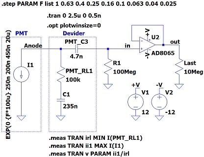
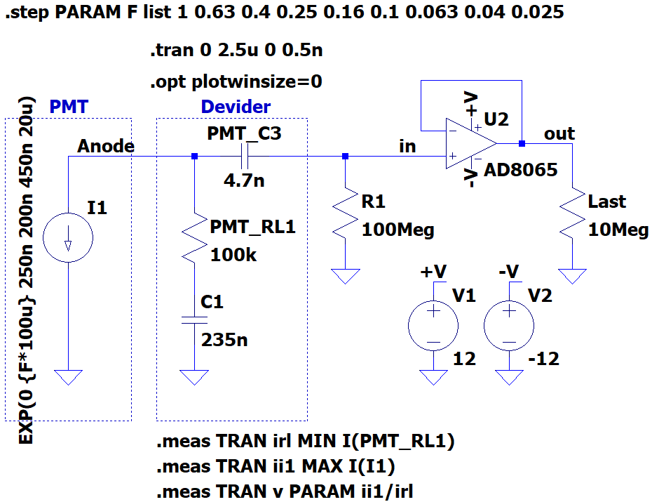
100k R1 100Meg C1 235n Last 10Meg V1 +V 12 V2 -V -12 EXP(0 {F*100u} 250n 200n 450n 20u .meas TRAN irl MIN I(PMT_RL1) .meas TRAN ii1 MAX I(I1) .meas TRAN v PARAM ii1/irl
in „Suche nach geeignetem OpAmp als Impedanzwandler“ · Analoge Elektronik und Schaltungstechnik · · Screenshots
-
Bild
Transistor IRL40B215
IRL40B215 Infineon IRJ328P B9P0
in „MOSFET IRL40B215 - Fake?“ · Analoge Elektronik und Schaltungstechnik · · Fotos
-
Bild
Tabellarische Messwerte von Strom und Spannung
Measurement: irl step 1 2 3 4 5 6 7 8 9 MIN(I(PMT_RL1)) -2.35818788497e-06 -3.77310061594e-06 -5.9426337916e-06 -9.43275153986e-06 -1.50924024638e-05 -2.35818788497e-05 -3.77310061594e-05 -5.94263328821e-05 -9.43275153986e
in „Suche nach geeignetem OpAmp als Impedanzwandler“ · Analoge Elektronik und Schaltungstechnik · · Screenshots
-
Datei
log.txt
command.c:145 script_debug(): command - ocd_command ocd_command type ocd_jtag newtap at91sam7a2 cpu -irlen 4 -ircapture 0x1 -irmask 0xf -expected-id 0x1f0f0f0f Debug: 59 312 command.c:145 script_debug(): command - ocd_jtag ocd_jtag newtap at91sam7a2 cpu -irlen 4 -ircapture 0x1 -i rmask 0xf -expected-id
in „USBProg zum Laufen bringen“ · Mikrocontroller und Digitale Elektronik ·
-
PDF
Bauteile.pdf
Treiber UCC3801 RS485Treiber 69 26 Treiber DS8921AM 9 27 EEPROM 93LC46A 1KSerielEEPROM 50 28 Mos-Fet IRL2910PBF 20V 61A 132mΩ TO-220AB NKanalMosFET 186 29 FlashSpeicher M28F512-12C1 SMD FlashSpeicher 6 30 Mos-Fet BUZ20 100V 12A 49 31 IGBT STGW45HF60WD 600V 45A TO-247 6 32 Mos-Fet IXKR40N60C 600V 38A NKanalMosFET
in „Elektronik Bauteile Neuwertig , meist Leistungselektronik“ · Markt ·
-
Bild
Ausschnitt eines technischen Datenblatts für einen MOSFET
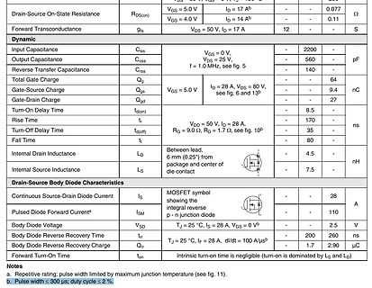
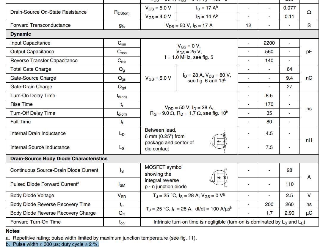
Drain-Source On-State Resistance RDS(on) VGS = 5.0 V ID = 17 A 0.077 Ω VGS = 4.0 V ID = 14 A 0.11 Forward Transconductance gfs VDS = 50 V, ID = 17 A 12 S Dynamic Input Capacitance Ciss VGS = 0 V, VDS = 25 V 2200 pF Output Capacitance Coss 560 Reverse Transfer Capacitance Crss f = 1.0 MHz, see fig. 5 140 Total Gate Charge Qg VGS = 5.0 V ID = 28 A, VDS = 80 V 64 nC Gate-Source Charge Qgs 9.4 Gate-Drain Charge Qgd 27 Turn-On Delay Time tD(on) 8.5 Rise Time tr 170 Turn-Off Delay Time tD(off) 35 Fall Time tf 80 Internal Drain Inductance LD 4.5 nH Internal Source Inductance LS 7.5 Drain-Source Body
in „Problem mit Mosfet IRL540 an 52V, öffnet nicht mehr“ · Analoge Elektronik und Schaltungstechnik · · Screenshots
-
Bild
Kennlinie Drain-Source-Strom gegen Drain-Source-Spannung
10000 VGS TOP 15V 1000 12V 10V 8.0V 6.0V 4.0V 3.0V 100 ID, Drain-to-Source Current (A) BOTTOM 2.0V 10 2.0V 1 0.1 0.01 20µs PULSE WIDTH TJ = 25°C 0.1 1 10 100 VDS, Drain-to-Source Voltage (V)
in „Austauschtyp für IRL 3803“ · Analoge Elektronik und Schaltungstechnik · · Screenshots
-
Bild
Kennlinie Drain-Source-Strom gegen Drain-Source-Spannung
10000 TOP VGS 10V 9.0V 7.0V 5.5V 4.5V 4.0V 3.5V 3.0V BOTTOM 1000 ID, Drain-to-Source Current (A) 100 ≤60µs PULSE WIDTH Tj = 25°C 10 3.0V 0.1 1 10 100 VDS, Drain-to-Source Voltage (V)
in „Austauschtyp für IRL 3803“ · Analoge Elektronik und Schaltungstechnik · · Diagramme
-
Bild
Tabelle der thermischen Widerstände
Thermal Resistance Parameter Min. Typ. Max. Units RθJC Junction-to-Case — — 3.3 °C/W RθCS Case-to-Sink, Flat, Greased Surface — 0.50 — °C/W RθJA Junction-to-Ambient — — 62 °C/W
in „Lineares Netzteil“ · Analoge Elektronik und Schaltungstechnik · · Screenshots
-
PDF
an-937_gateDrive.pdf
10 28 15 72 40 50 4.5 5 28 15 72 44 56 Table 4: Typical Resistive Switching Times for IRL540 and IRF540 TTL families do not actually deliver 5V in thOHcondition, even into an open circuit. The 5V level can, however, be reached by the addition of a pull-up resistor from the output pin to
in „Gatekapazität (FET)“ · Analoge Elektronik und Schaltungstechnik ·
-
PDF
Bauteile.pdf
W5NB90 900V 9,7S 1Ω 282 36 Bauteil Mos-Fet STW13NB60 600V 13A 0,54mΩ NKanal 112 37 Bauteil Mos-Fet IRL 2910PBF 20V 61A 132mΩ TO-220AB NKanalMosFET 186 38 Bauteil Mos-Fet BUZ20 100V 12A 49 39 Bauteil Mos-Fet IXKR40N60C 600V 38A NKanalMosFET 11 40 Bauteil Mos-Fet IRFP054 60V 70A TO-247 Powermosfet 78 41
-
PDF
MOSFET_Switched_Mode_Amplifiers_Part_2_-_Handimans_Guide.pdf
with good success, loadingeffectofQ2.Drainvoltagerises recommendation is sometimes given to IRF510vs.IRL520 and surprisingly, the high efficiency above 12v Vdd as the current stored in raisethemosfetdrainvoltageforhigher The IRL520 is a logic family mosfet, causes little heating of these very L1 now dumps
-
Bild
Schaltplan mit MOSFET und Heizdraht
+52V, 40Ohm (Heizdraht), Taster, IRL540 (n-Kanal-MOSFET), D, G, S, GND, +7,5V, 56kOhm
in „Problem mit Mosfet IRL540 an 52V, öffnet nicht mehr“ · Analoge Elektronik und Schaltungstechnik · · Schaltpläne
-
PDF
Zigbee_Lightstrip-Controller.pdf
Sehr preiswert (0,49€/Stk bei Reichelt Elektronik, 4,40€/10Stk bei eBay zzgl. 2,50€ Versand) sind IRL540N. Diese sind von den Leistungsdaten für den Einsatz in einem Lightstrip-Controller natürlich erheblich überdimensioniert (100V, 35A), von der Bauform (TO220) jedoch sehr handlich bei Selbstbauprojekten
in „Dimmbare 12V~ LED-Strahler mit PWM dimmen - welche Gleichspannung?“ · Analoge Elektronik und Schaltungstechnik ·
-
Bild
Kennlinien von MOSFETs IRF3708, IRL3803 und IRLB4030
IRF3708, IRL3803, IRLB4030, ID, Drain-to-Source Current (A), VGS, Gate-to-Source Voltage (V), VDS, TJ = 25°C, TJ = 175°C, VGS = 10V, ID = 15A, VGS = 4.5V, ID = 12A, VGS = 2.8V, ID = 7.5A, VDS = 15V, 20us PULSE WIDTH
in „Austauschtyp für IRL 3803“ · Analoge Elektronik und Schaltungstechnik · · Diagramme
-
Bild
Ausschnitt aus einem Datenblatt mit elektrischen Kennwerten
RL540NPbF International IOR Rectifier Electrical Characteristics @ TJ = 25°C (unless otherwise specified) Parameter Min. Typ. Max. Units Conditions V(BR)DSS Drain-to-Source Breakdown Voltage 100 — — V VGS = 0V, ID = 250µA ΔV(BR)DSS/ΔTJ Breakdown Voltage Temp. Coefficient — 0.11 — V/°C Reference to 25°C, ID = 1mA RDS(on) Static Drain-to-Source On-Resistance — — 0.044 Ω VGS = 10V, ID = 18A @ — — 0.053 Ω VGS = 5.0V, ID = 18A @ — — 0.063 Ω VGS = 4.0V, ID = 15A @ VGS(th) Gate Threshold Voltage 1.0 — 2.0 V VDS = VGS, ID = 250µA gfs Forward Transconductance 14 — — S VDS = 25V, ID = 18A IDSS Drain-to-Source
in „Umsetzung eines 5V Output mit ESP32 und AQY Halbleiterrelais“ · Mikrocontroller und Digitale Elektronik · · Screenshots
-
PDF
IS25LP128.pdf
6.5 and Table 6.6 Table 6.5 Function Register Format Bit 7 Bit 6 Bit 5 Bit 4 Bit 3 Bit 2 Bit 1 Bit 0 IRL3 IRL2 IRL1 IRL0 ESUS PSUS TBS Reserved Default 0 0 0 0 0 0 0 0 Table 6.6 Function Register Bit Definition Bit Name Definition Read- Type /Write Bit 0 Reserved Reserved R Reserved Top/Bottom Top/Bottom
-
PDF
FLASH_IS25LP128.pdf
6.5 and Table 6.6 Table 6.5 Function Register Format Bit 7 Bit 6 Bit 5 Bit 4 Bit 3 Bit 2 Bit 1 Bit 0 IRL3 IRL2 IRL1 IRL0 ESUS PSUS TBS Reserved Default 0 0 0 0 0 0 0 0 Table 6.6 Function Register Bit Definition Bit Name Definition Read- Type /Write Bit 0 Reserved Reserved R Reserved Top/Bottom Top/Bottom
in „STM32L4 memory-mapped QSPI Lesegeschwindigkeit maximieren“ · Mikrocontroller und Digitale Elektronik ·