Figure 5. VFversus IFfor Different Temperatures (VDD = 15 V) 1,400 1,400 VPN = 300 V VPN = 300 V )1,200 V = 15 V ) 1,200 V = 15 V m DD m DD ( s s1,000 s 1,000 L L g 800 g 800 i TJ= 100°C i c 600 c 600 i i S S TJ= 100°C , 400 ,F 400 O TJ= 25°C O TJ= 25°C E 200 E 200 0 0 0 5 10 15 20 25 30 0 5 10 15 20
und geeignetem FET-Typ im Bereich um net s'cb aus: Bild5: Vergleich der eingangsignalabhän 100...200 Q. gigen Signal/Rauschspannungsabstände F RM m einer AM-Mischstufe ohne (1) und mit (2) Der Sourcewiderstand Rs bestimmt den 1 + - ] / - (4) FET-Vorstufe Drainstrom /D. Er wird so gewählt, daß der ^
2.5 V [ e 2.0 e 2.0 a 6.81 kΩ 12 Ω a 27 kΩ 47 kΩ 68.1 Ω l 1.5 o 1.5 V V 1.0 1.0 0.5 0.5 0.0 0.0 0 200 400 600 800 1000 0 1000 2000 3000 4000 5000 6000 Time [h] Time [h] Temperature performance Load 12k Ω Cell capacity at various loads 3.5 300 23°C 3.0 250 ] 70°C ] 2.5 A [ m 200 70°C e 2.0 y t -20°C 0°C 70°C c 150 23°C o 1.5 p 0°C V a 100 -20°C 1.0 C 50 0.5 0.0 0 0 200 400 600 800 1000 1 10 100 Time [h] Load [kΩ] *In applications where the battery is exposed to temperatures above 70 °C, please contact Renata for consultancy. Information and contents in this data sheet
erledigen kann. 16 oder 32 Samples sollten dicke ausreichen. Der ADC benötigt eine Clock zw 50 .. 200kHz! Er hat dafür einen eigenen Prescaler den du passend zur Haupt-Clock einstellen musst. Was für einen Quarz hast du? Mit ADMUX = (ADMUX & 0xF8) setzt du: - die Reference Voltage auf die interne
ganze ran soll. [c]void adc_init() { // Set the ADC reference to AVcc ADMUX = (1 << REFS0); // Enable ADC and set prescaler to 128 (16 MHz / 128 = 125 kHz) ADCSRA = (1 << ADEN) | (1 << ADPS2) | (1 << ADPS1) | (1 << ADPS0); } [/c]
man die gebräuchlichsten Balkenanzeigen auch auf Punkt umstellen kann, hatte ich auch schon vor fast 200 Beiträgen mal gepostet. EOT
Matthias S. schrieb im Beitrag #8106548: > Thorsten P. schrieb: >> Ob zB die Spannung mit 3m oder 200m abstand wäre ist mir sonnenklar. >> Vieles einfach nur Spekulationen. ahh unglücklich formuliert . stimmt. Sollte heißen : 200m Kabel verschlechtern das Signal,ist mir schon klar! Ich schreibe
https://www.amazon.de/WABECO-Magnet-Messstativ-Messuhr-Zentralklemmmung-Messuhrhalter/dp/B00GISNB2W/ref=asc_df_B00GISNB2W Damit solltest du das ausreichend genau messen können. Es muss für deine Belange wohl keine Mitutoyo sein.
Grumpy schrieb im Beitrag #8104314: > Was ich tatsächlich, mea culpa, bei einer 200 EUR Maschine nicht > unbedingt so erwartet habe. Na ja, 200€ ist halt nicht viel. Alleine ein Albrecht Bohrfutter kostet mindestens so viel. Und eine TBM ist halt kein Massenprodukt wie eine Waschmaschine
version of the specification. The version of the product specification will be updated in time.Please refer to the latest information on the official website; *The copyright and the final interpretation right of the product belong to Dongguan opsco Optoelectronic Technology Co., Ltd. if you have special
Tischkreissäge-Modellbau,Tischkreissäge-Klein,7-Gang-Netzteil-Hönverstellbarer-Holzbearbeitung/dp/B0G8X83875/ref=asc_df_B0G8X83875 . Mit dem mitgelieferten Hartmetallblatt läßt sich Leiterplattenmatererial problemlos schneiden. Auch dünne Alubleche und Aluprofile aus dem Baumarkt lassen sich damit hervorragend
Tischkreissäge-Modellbau,Tischkreissäge-Klein,7-Gang-Netzteil-Hönverstellbarer-Holzbearbeitung/dp/B0G8X83875/ref=asc_df_B0G8X83875) gekauft. Die tut jetzt seit 5 Jahren und hat damit ihr Geld mehr als verdient
operating area RBSOA O = 20A, VCE = 450V Full Square Short circuit safe operating area SCSOA VCE = 200V 4 μs Allowable offset voltage slew rate dv/dt U (V, W) - U - (V -, W -) terminal -50 50 V/ns In the case without the instruction, the voltage standard is V SS terminal voltage. No.A1723-2/7 STK625-
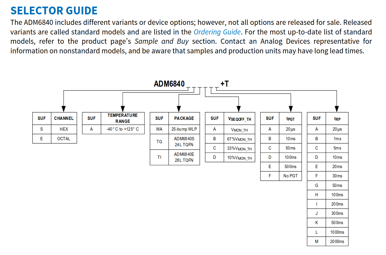
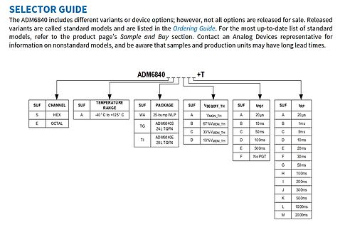
standard models and are listed in the Ordering Guide. For the most up-to-date list of standard models, refer to the product page's Sample and Buy section. Contact an Analog Devices representative for information on nonstandard models, and be aware that samples and production units may have long lead times
warming up. − Flashing light indicates that the preselected temperature has been C reached. Note Please refer to the accessories section on page 18 for a list of tools P that can be connected to the WD 1 (M) / WD 1000 (M). U H K S L S E E V L L 8-18 WD 1 (M) / WD 1000 (M) 6 Operating the device 6.1 Setting
commutation (4Q) or very high commutation (3Q, Snubberless™) capability • BTA series UL1557 certified (file ref: 81734) G G • Packages are RoHS (2002/95/EC) compliant A12 A1A2 • Insulated tab (BTA series, rated at 2500 V ) RMS TO-220AB TO-220AB Ins. A2 Applications • Snubberless versions (BTA/BTB...W and T1635
Current |OUT| 5 15 A VOL0.2 V DDV OH >0.8 VDD DCF77 Output Pulses T 100ms 1 Vrms V IN 95 ms T 200ms 20 mVrms, see note below! 195 MSF Output Pulses T 100ms 1 Vrms V 120 ms IN T 200ms 20 mVrms, see note below! 220 T 300ms 320 T 500ms 520 WWVB Output Pulses T 200 ms 200ms 1 Vrms V IN T 500ms
komplett, absolut https://www.amazon.de/Hailege-Magnetic-Measurement-Encoder-precision/dp/B0B778L7T3/ref=asc_df_B0B778L7T3 Du musst halt an einem Ende der Achse Platz haben.
Erfahrung. Das Drehmoment muß nicht groß sein, so eine voll belegte Filterscheibe wiegt vielleicht 200g bei ca. 140mm Durchmesser. Versorgung über USB wäre Ideal.
Input common 2 V V+ 7 mode range from V to V – 1.3V. Input current typically + 10pA at 25°C. 3 IN+ – REF 6 HYST (Pin 5): Hysteresis Input. Connect to REF if not 4 IN– 5 used. Input voltage range is fromV REF to REF – 50mV. HYST REF (Pin 6): Reference Output. 1.182V with respect 1540 • PD – toV .Cansourceupto1mAandsink10µAat25
proprietary CC/CV control, system needs to be designed in DCM in Figure.3. mode for flyback system (Refer to Typical Application Diagram in page1). In the DCM flyback converter, the output voltage can be sensed via the auxiliary winding. During MOSFET turn-on time, the load current is supplied from the
[139/1714] Building C object esp-idf/esp_netif/CMakeFiles/__idf_esp_netif.dir/lwip/netif/esp_pbuf_ref.c.obj [140/1714] Building C object esp-idf/lwip/CMakeFiles/__idf_lwip.dir/apps/sntp/sntp.c.obj [141/1714] Building C object esp-idf/esp_netif/CMakeFiles/__idf_esp_netif.dir/lwip/netif/wlanif.c.obj [
1. Refer to the taping drawing. Seiko Instruments Inc. 3 BATTERY PROTECTION IC FOR 2-SERIAL-CELL PACK S-8242A Series Rev.3.0 _00 2. Product Name List (1) SOT-23-6W Table 1 Overcharge Overcharge Overdischarge
Längstransistoren die Ausgangsspannung über R19 ins Negative rutscht. D6 begrenzt die Spannung zwar, aber ca. -200mV bleiben am Ausgang stehen. Während das beim Ausschalten des Netzteils notwendig ist, sollten der Basisstrom der Transistoren bei der ON/OFF-Funktion nicht abgeschaltet werden. Der zusätzliche P-MOS
Soll-Eingang kann per potentialtrennenden Optokoppler erfolgen. - Längsregler mit Darlington MJH 11020G (200V/15A/150W). hfe könnte auch bei Minustemperaturen passen: 5mA*600=3A. Damit Verzicht auf BD139 möglich. In LTSpice ist derzeit nur ein langsamer TIP122. - Netzteilschutz mit Si-Diode D3 (Schutz vor
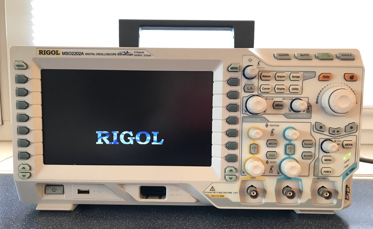
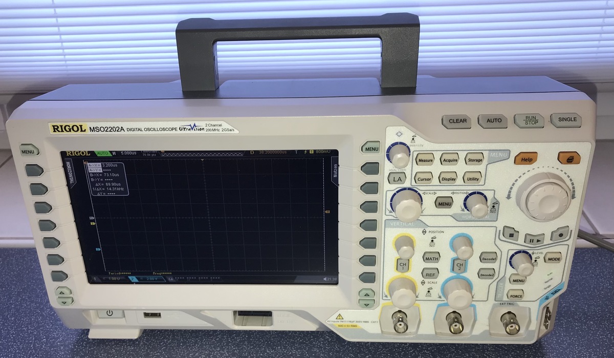
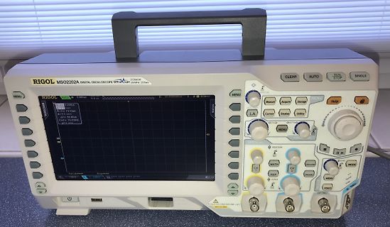
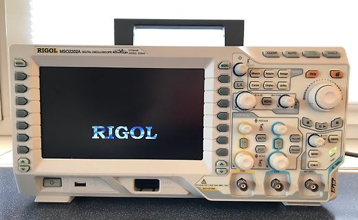
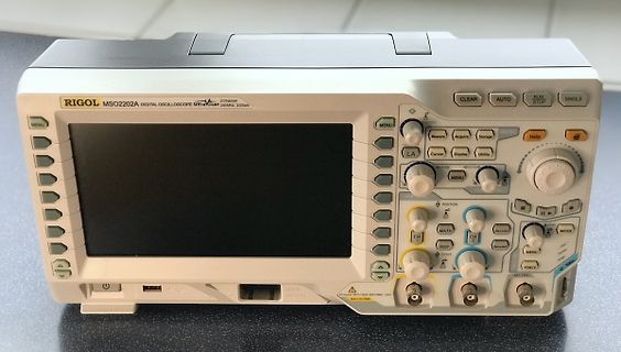
RIGOL MSO2202A DIGITAL OSCILLOSCOPE 2 Channel UltraVision 200MHz 2GSa/s MENU Acquire Storage MENU Help LA Cursor Display Utility MENU VERTICAL POSITION MATH Decode1 MENU HORIZONTAL LEVEL MODE REF FORCE SCALE CH1 CH2 LOGIC D0-D15
Electrical characteristics MC34063AB, MC34063AC, MC34063EB, MC34063EC 4 Electrical characteristics Refer to the test circuitsCCV = 5 V, A = TLOW to THIGH , unless otherwise specified.(a) Table 5. Oscillator Symbol Parameter Test conditions Min. Typ. Max. Unit OSC Frequency V PIN5= 0V, CT= 1 nF, A = 25
VCCUVLO UVLO Detect Threshold Voltage V UV 2.9 3.1 3.3 V VCC sweep down UVLO Hysteresis VUVHYS 30 100 200 mV VREF Output Voltage VREF - 3.0 - V VREG Output Voltage VREG 4.8 5.0 5.2 V OVLO Threshold Voltage VREGOV 5.2 5.4 5.6 V V REGsweep up OVLO Hysteresis V REGOVHYS 30 100 200 mV Oscillator Oscillating
) Pressure relief vent 4.0±0.5 Rated voltage (200V) 25 A 30 B Series name 35 C +0.2 Type 0.-0.1 +01 1 0.8-. 0±01 5 0 0 4 2 2-2φ0.1 +0.2 1.5-0.1 (PC board hole dimensions) (Terminal dimensions) The other terminal is also available upon request. Please refer page 328 for schematic of dimensions. Frequency coefficient of rated ripple current Frequency (Hz) 50 60 120 300 1k 10k 50k or more 16 to 100V 0.88 0.90 1.00 1.07 1.15 1.15 1.15 Coeff. 160 to 250V
% SPEICHER_INTERVALL_IMPULSE == 0) { eventMicros = micros(); eventPpsRef = ppsMicrosRef; // GPS-Zeitstempel für diesen Moment sichern logStunde = gpsStunde; logMinute = gpsMinute; logSekunde = gpsSekunde; logTag = gpsTag; logMonat
if (gesamtImpulsZaehler % SPEICHER_INTERVALL_IMPULSE == 0) { eventMicros = micros(); eventPpsRef = ppsMicrosRef; [/code] und micros() ist eine Systemzeit, die überlaufen kann. https://docs.arduino.cc/language-reference/de/en/functions/time/micros/
between sending of each datum. Auto Reset should be performed after checking STA3 = 1 (STA2 = 1). Refer to the following flowchart. a) Auto Read mode b) Auto Write mode 22 2002-01-07 T6963C ● Data Read / Write Code Hex. Function Operand 11000000 C0H Data Write and Increment ADP Data 11000001 C1H Data
sie be Bild1: 20-MHz-Zwelkanaioszil- inden USA wird mit 700 Dollar loskopeder Low-cost-Klasse von 200mV-1000V; 2 mA- angegeben. trägtfür die Abstimmoptimie (Siemens-Pressebild) 10A und 0,1Q-20 M-Q sowie rung bei Inbetriebnahme typ. Halbleiterteskönnen mitdem Antennen genau 2 s,danach für den Betriebnur
Mini-Digital-DC-Voltmeter, Dreileiter 0V-100V Mini-DC-Voltmeter. https://www.amazon.de/dp/B0C3HC3XJB?ref=ppx_yo2ov_dt_b_fed_asin_title VG Markus
Ja, das geht. Die haben vor dem AD-Eingang einen recht niederohmigen Spannungsteiler (so etwa 200k bei meinen Exemplaren) auf dem Board. Den musst du finden und ausbauen/umdimensionieren; das ist einfach, sind ja nur ein paar Teile drauf. Ich habe das vor ein paar Jahren mit 2 Geräten gemacht. Der
was developed for flexible deployment in the field. It combines a robust portable receiver (R&S®PR200) inside an impact-resistant transport case with a high-performance DF antenna (R&S®ADD507). The complete system can be assembled entirely without tools and has a total weight of around 27 kg. Specific
backhaul, all without adding cost or complexity to the network. [/c] ### WCH CH32V407/467 – 200 MHz und Fast-Ethernet-MAC und optionales PSRAM. Im Hause WCH arbeitet man permanent an der „Leistungssteigerung“ der hauseigenen MCUs. Auf Basis eines RISC-V-Kerns steht nun eine neue Kern-Familie
Trafos: mit einem 230-230-Trenntrafo und einem 230-115-Trenntrafo[code] L2 S S S (230V, 200V reichen aus) S S 115V 230V |~~~~~~ N ~~~~~~~~~~~~ L1 S S S (230V, 200V reichen aus) S S L3[/code]
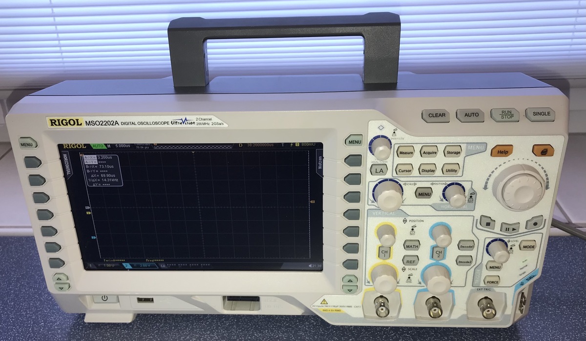
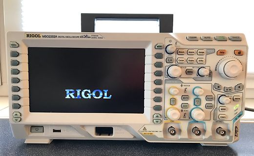
RIGOL MSO2202A DIGITAL OSCILLOSCOPE UltraVision 200MHz 2GSa/s
MENU AUTO RUN STOP
MENU Measure Acquire Storage
LA Cursor Display Utility
VERT
POSITION
MATH
REF
SCALE
DECODE
MENU
EXT
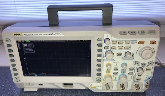
A: 2.00us
B: 73.10us
AX: 69.80us
BX: 14.31us
500mV
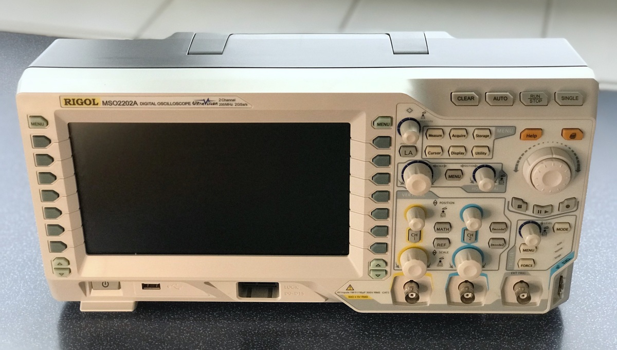
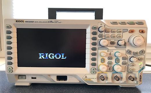
RIGOL MSO2202A DIGITAL OSCILLOSCOPE 2 Channel UltraVision 200MHz 2GSa/s MENU Acquire Storage MENU Help LA Cursor Display Utility MENU VERTICAL POSITION MATH Decode1 MENU HORIZONTAL LEVEL MODE REF FORCE SCALE CH1 CH2 LOGIC D0-D15
Wdg ist dessen Wickelschema. Die beiden 5er parallel und die 86 als Ausgang. Von 3,6V rauf auf ca. 200V oder mehr. ich habe zum einen 200V Schottkys und zum anderen schnelle 400V Dioden. So kann ich testen, ob das von den Verlusten her einen relevanten Unterschied macht. Wenn nicht, kann ich auch die
RIGOL MSO2202A DIGITAL OSCILLOSCOPE UltraVision 200MHz 2GSa/s
MENU AUTO RUN STOP
MENU Measure Acquire Storage
LA Cursor Display Utility
VERT
POSITION
MATH
REF
SCALE
DECODE
MENU
EXT
A: 2.00us
B: 73.10us
AX: 69.80us
MAX: 14.91MHz
RIGOL MSO2202A DIGITAL OSCILLOSCOPE UltraVision 200MHz 2GSa/s MENU Acquire Storage CLEAR AUTO RUN STOP SINGLE LA Cursor Display Utility MATH VERTICAL POSITION MENU CH REF DECODE MODE FORCE EXT TRIG LOGIC
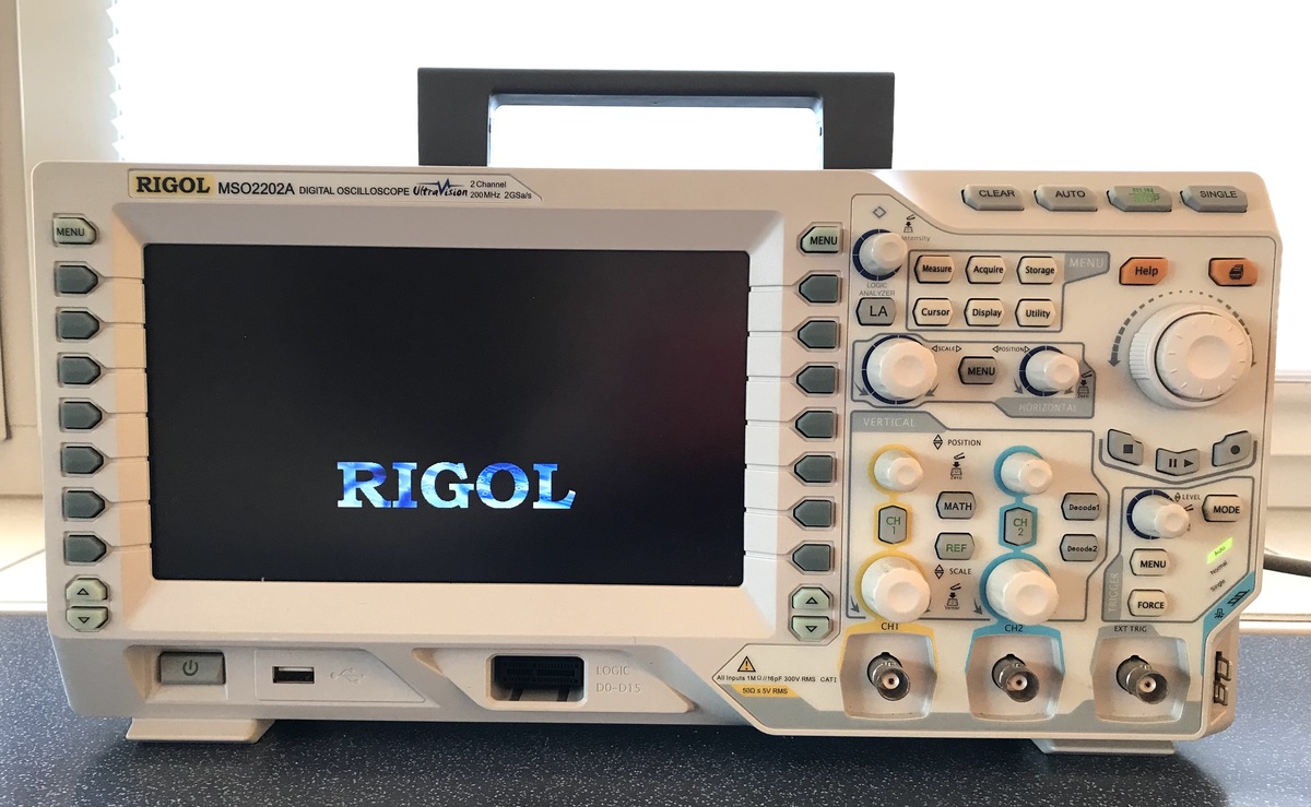
RIGOL MSO2202A DIGITAL OSCILLOSCOPE 2 Channel UltraVision 200MHz 2GSa/s MENU Acquire Storage MENU Help LA Cursor Display Utility MENU VERTICAL POSITION MATH Decode1 MENU HORIZONTAL LEVEL MODE REF FORCE SCALE CH1 CH2 LOGIC D0-D15
w, activate the counting application + 20pcs The current piece count and current reference weight nRef + 20 pcs are output wRef + 0.8750 g Fill-in required quantity + 200pcs Press the g/W key + 200pcs Press the z/T key, activate checkweighing + 200pcs The tolerance limit symbol flashes; the user guide
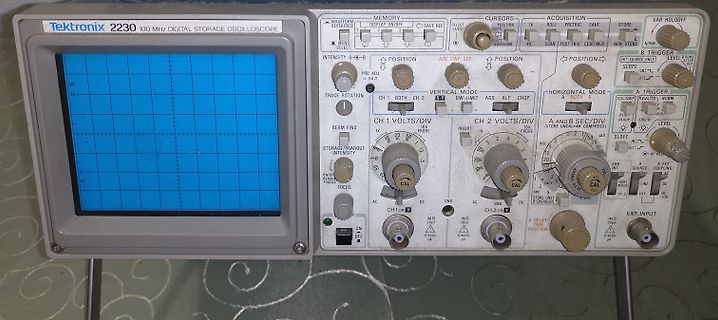
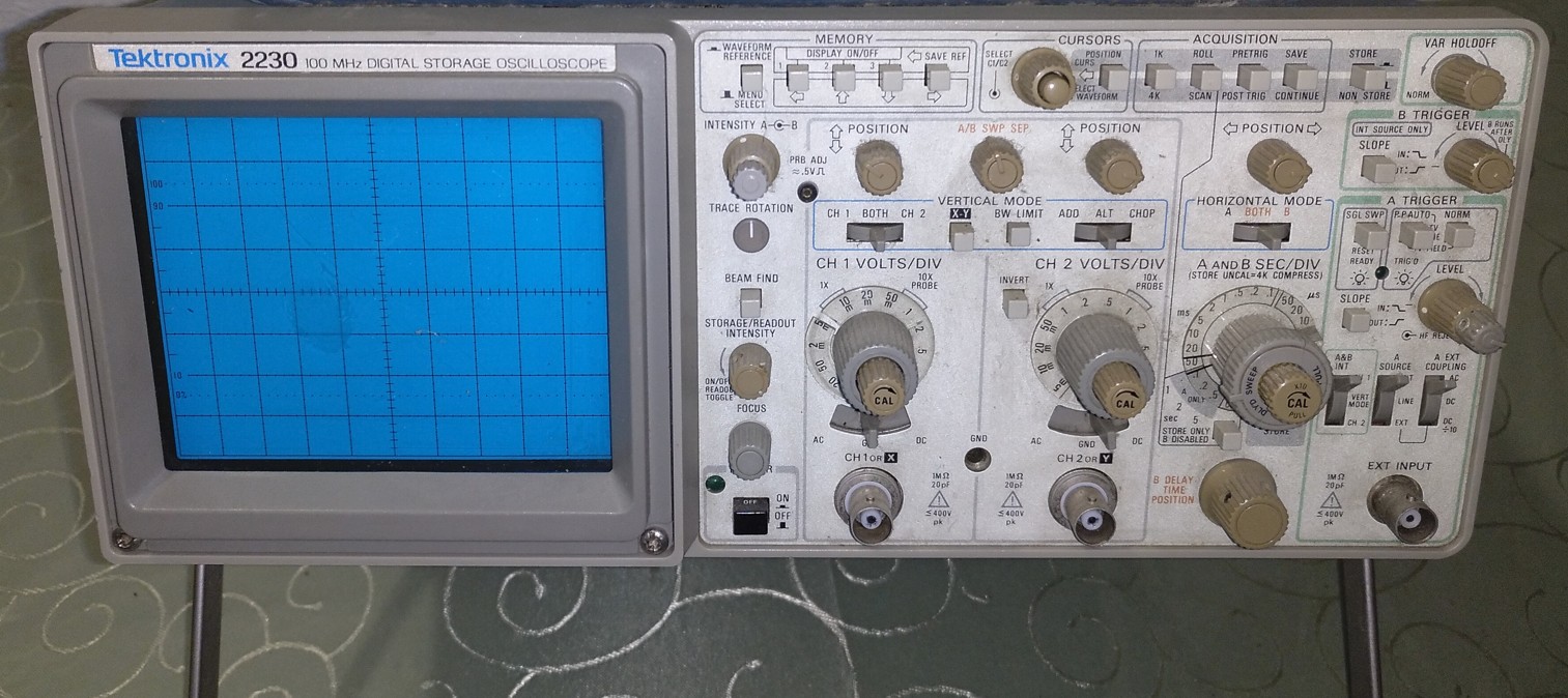
Tektronix 2230 100 MHz DIGITAL STORAGE OSCILLOSCOPE
WAVEFORM REFERENCE
MEMORY DISPLAY ON/OFF
SAVE REF
SELECT CURSOR
ACQUISITION
ROLL
PRETRIG
SAVE
STORE
VAR HOLD OFF
INTENSITY A-B
POSITION
TRACE ROTATION
A/B SWP SEP.
POSITION
B TRIGGER
INT SOURCE ONLY
LEVEL AFTER
SLOPE
VERTICAL MODE
CH 1 VOLTS/DIV
CH
tent DMA Acknowledge assertion during memory refresh periods. If DACK is asserted when REF is ac RCVCCO Receive Collision Count Overflow JAB Jabber tive, DACK assertion is ignored. REF is monitored to eliminate a bus arbitration problem observed on some MISS Missed Frame ISA platforms. MERR

 Bild
 Bild
 Bild
 Bild
 Bild
 Bild
 Bild
 Bild
 Bild
 Bild
 Bild