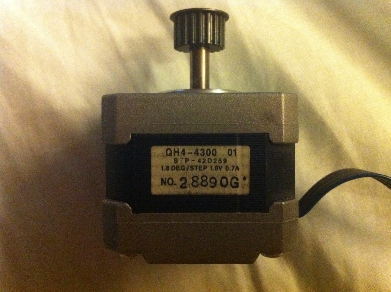
ein Gruß zur ganzen Forumsdiskussion...

ihr könnt mir helfen, um den datasheet und die Fabrik von diesem Motor
wiederzuerkennen, was seht ihr in Foto Anlage?
ich würde gern nur diesen Motor QH4-4300-01 mit einem driver Controller
für Funktion arbeiten lassen von weiter und rückwärts und Regelung von
Schnelligkeit.
aber welche link wire cable nicht muß ernähren.
eventuell welch Controller driver muß acquistared für jene einfachen
Funktionen.
inzwischen Gruß und ich danke, da vertraue ich in einer Hilfe an
Could you please rewrite your post in english?

I think you want to build a stepper controller.
Maybe you check out the old workhorses like L297 and L298 to do that
job. Theyre quite cheap, too.

The motor looks like salvaged from a scanner or printer or so.
With a multimeter you can easily measure the inner circuit and whether a
bipolar or unipolar driver is needed.

regards, mf
Instead of using a malformed automatic translation into german you'd be
better off asking in english.
I can't answer your question in italian, sorry 'bout that.

Non parlo italiano
regard to the whole forum...

I am had to make to work it with a controller simple driver.
you can help to recognize me the datasheet and the factory of this motor
in photo the enclosure?
I have to make to work this motor QH4-4300-01 with three simple
movements, before - back and adjustable speed with a controller driver.
however I need the factory, datasheet voltage.
it has 4 cables, 3 grey and one blue. which is the scheme link wire to
feed it?

possible it owes what controller driver acquistared for those functions
simple.
in the meantime regard and I thank, confiding in one help of yours
Uhh, what? This is a stepper motor. All the data you need is printed
right on the label! Since it has 4 wires it's bipolar and you need two
H-bridges to drive it.

What is this, some kind of homework assignment?
If you would have taken a closer look on the sticker on the motor, you
should have seen hat the maximum average current per coil is 700mA. The
voltage of a DC source is 1.8V then. The resistance of one coil should
be near 2.5Ω.

Four wires...seems like a bipolar motor to me.
As I said before, a multimeter or continuity buzzer can easily point out
which wire goes where.
hallo Malignes Melanom.
Yes.. the homework assignment, has to turn to walk before and back and
to regulate the speed. you can give me you the datasheet volt power of
this motor, capico alone angle deg 1.8 of steep, 1,8v and 0.7A. which
driver controller do I have to purchase or to build?
hi STK500-Besitzer..
respectively 1 = grey, 2 = grey, 3 = grey, 4 = blue.
now, cable 4 with cable 3 are open. cable 4 with cable 2 are close.
cable 4 with cable 1 are open. cable 1 with cable 2 are open. cable 2
with cable 3 are open. cable 1 with cable 3 are close. the ohmeter not
to give any measurement of impedance, but only open or closed.
A typical driving pattern for a stepper motor looks like this:

Forward:
Voltage Coil1: 0 + + + 0 - - -
Voltage Coil2: + + 0 - - - 0 +
         Time: 1 2 3 4 5 6 7 8 1 2 3 ...

Backward:
Voltage Coil1: 0 + + + 0 - - -
Voltage Coil2: - - 0 + + + 0 -
         Time: 1 2 3 4 5 6 7 8 1 2 3 ...

This can easily be achieved with a decimal counter and some glue logic
or a decoder made with a diode/resistor matrix.
The output of your logic circuit should be four signals, two for each
H-bridge. One H-bridge is made with four bipolar transistors(so you need
eight, four PNP and four NPN, maybe like
http://talkingelectronics.com/projects/200TrCcts/101-200TrCcts.html#29).
I recommend to put a resistor in series with the coils, because of their
low resistance.

regards, mf

PS: Forward/reverse can also be achieved by switching one coil's
polarity with a relay or inverting the control signals for this coil.
marco seri schrieb:> cable 4 with cable 2 are close.
Found one coil!
marco seri schrieb:> cable 1 with cable 3 are close.
Congrats, you found the other one!
thanks minifloat for your technical answer, but I don't have your
preparation of study school,
but I have a knowledge of base... can you recommend me you a small
circuit
electronic pcb to be made to work with my motor?
to try the motor to now turn with that volt power I have to act, and
above all which wire link I have to connect?
thanks, you are all very available ones.
you can give me all the datasheets imput wire-link gnd, positive, egg..
correct imput operation of this motor?
it has only to work with homework you work:  before - back, adjustable
speed, interrupter stop and go. PC control is not important with
parallel port.
what can you recommend me?
The "mshield" only works with an arduino or other microprocessor boards,
there's no control logic on it. Everithing has to be done in software.


You wanted a more standalone solution, why don't give the "Big Easy" a
go.
Switches for direction et cetera are still missing.
Just wire them like in my post above.
I don't believe that it can do 2A, but since you only need 700mA...

mf

PS: manually clocking 3200 steps/revolution for microstepping seems a
bit boring to me. just google how an additional 555 clock generator can
be made.
Rufus Τ. Firefly schrieb:> Instead of using a malformed automatic translation into german you'd> be better off asking in english.
All we got is malformed english translation... ;-)
work-it schrieb:> it has only to work with homework you work: before - back, adjustable> speed, interrupter stop and go.
With your level of knowledge this is a demanding task... :-o
Why don't you just write, WHAT you want to do with this motor?
Do you want to run a robot? Or what else?
Do you have any knowledge in electronics?
Lothar Miller schrieb:> All we got is malformed english translation... ;-)
Ja, ich hatte ja gehofft, daß er statt einer automatischen Übersetzung
it-de selbst in en schreiben würde, aber das sieht irgendwie immer noch
nach einer automatischen Übersetzung it-en aus.
Die aber ist immerhin verständlicher als die it-de-Variante.
Also schlimmer gehts echt nicht, da werden unzählige Lösungsvorschläge
gebracht und der kommt jetzt wieder angesch***en mit basic knowledge.
Wenn er das hätte, hätte er nicht hier gefragt.

dear "work-it"
1. please stop translating with google
2. write directly in english please

mf
Ich brauche allein einen einfachen Fahrerkontrolleur der zu machen,
abgewechselten Sinn den Motor abzugeben und beherrscht die
Geschwindigkeit.. aber, ohne vom Computer mit parallelem Hafen überprüft
zu werden, nur Handbuch..

 IMG_0046.JPG
(360 KB)
IMG_0046.JPG
(360 KB)