LCD an ATTiny2313

OP #2992655
Lesenswert?

Hallo,
ich habe bisher nur Arduinos benutzt und wollte nun mal einen ATtyin2313 
direkt mit Atmel Studio nutzen.
Ich wollte als erstes mal mein Display testen und habe mir die Fleur Lib 
besorgt und in den Projektordner gelegt.
In der lcd.h habe ich folgendes angepasst, bzw. gelassen:

XTAL auf 8000000 geändert
1
#define XTAL 8000000
2

3

4
#define LCD_PORT         PORTA        /**< port for the LCD lines   */
5
#define LCD_DATA0_PORT   LCD_PORT     /**< port for 4bit data bit 0 */
6
#define LCD_DATA1_PORT   LCD_PORT     /**< port for 4bit data bit 1 */
7
#define LCD_DATA2_PORT   LCD_PORT     /**< port for 4bit data bit 2 */
8
#define LCD_DATA3_PORT   LCD_PORT     /**< port for 4bit data bit 3 */
9
#define LCD_DATA0_PIN    PB0            /**< pin for 4bit data bit 0  */
10
#define LCD_DATA1_PIN    PB1            /**< pin for 4bit data bit 1  */
11
#define LCD_DATA2_PIN    PB2            /**< pin for 4bit data bit 2  */
12
#define LCD_DATA3_PIN    PB3            /**< pin for 4bit data bit 3  */
13
#define LCD_RS_PORT      LCD_PORT     /**< port for RS line         */
14
#define LCD_RS_PIN       PB4            /**< pin  for RS line         */
15
#define LCD_RW_PORT      LCD_PORT     /**< port for RW line         */
16
#define LCD_RW_PIN       PB5            /**< pin  for RW line         */
17
#define LCD_E_PORT       LCD_PORT     /**< port for Enable line     */
18
#define LCD_E_PIN        PB6            /**< pin  for Enable line     */

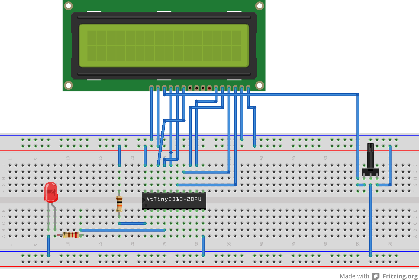
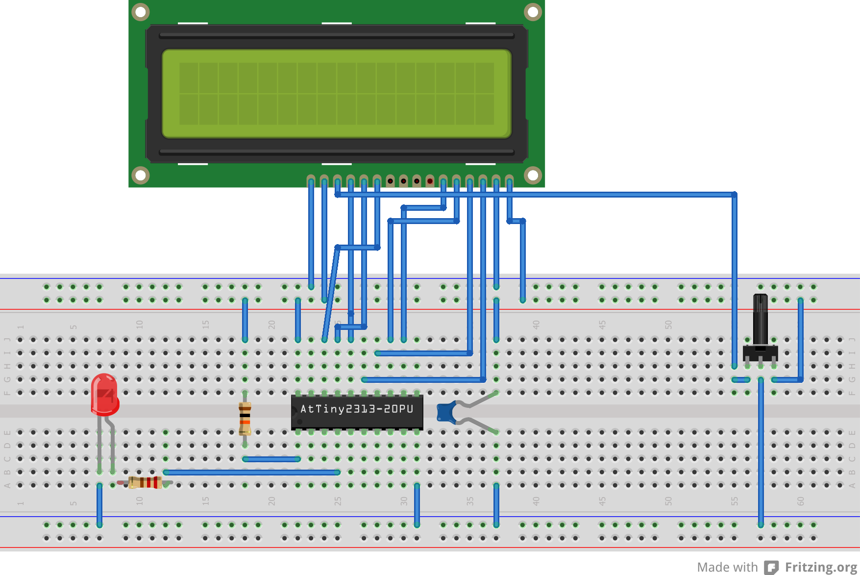
Nun habe ich die Anschlüsse des HD44780 kompatilen Displays wie folgt an 
den Attiny angeschlossen (4bit Modus)
1
LCD_DATA0_PIN(DB4)    -> PB0
2
LCD_DATA1_PIN(DB5)    -> PB1
3
LCD_DATA2_PIN(DB6)    -> PB2
4
LCD_DATA3_PIN(DB7)    -> PB3
5
LCD_RS_PIN(RS)       -> PB4
6
LCD_RW_PIN(R/W)       -> PB5
7
LCD_E_PIN(E)        -> PB6

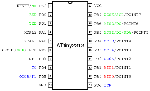
Nun verstehe ich noch nicht so ganz wie ich die PIN's PB0-PB6 oben bei 
definde korrekt nutze.. also welche nummern diese dann haben!?

Weil so funktioniert es leider noch nicht ;(

Vielen Dank


P.S:
So wollte ich das dann testen:
1
/*
2
 * Attiny2313_LCD_Test.c
3
 *
4
 * Created: 10.01.2013 19:18:53
5
 *  Author: dehein
6
 */ 
7

8

9
#include <avr/io.h>
10
#include "lcd.h"
11
#include "lcd.c"
12

13

14
int main(void)
15
{
16
  lcd_init (LCD_DISP_ON);
17
  lcd_puts ("Hello World :)");
18

19

20
for (;;){};
21
}
OP #2992788
Lesenswert?

den Programmer habe ich ab. Ich habe noch einen 10K an Reset zu VCC. 
Sonst ist da nichts dran.
Habe gerade die ganzen Kabel auch nochmal geprüft, das müsste so 
stimmen...

was meinst du mit #1, ich habe oben ja z.B. für

#define LCD_DATA0_PIN    PB0            /**< pin for 4bit data bit 0  */

was dann zu DB4 am LCD geht
Gast #2992794
Lesenswert?

Hi,

zwar sind PB0 und PA0 als defines für den Compiler identisch, aber nicht 
für den uController.
1
#define LCD_PORT         PORTA        /**< port for the LCD lines   */
muss wohl so heissen:
1
#define LCD_PORT         PORTB        /**< port for the LCD lines   */

Gruß
Hermann-Josef
OP #2992803
Lesenswert?

sorry, wenn ich blöd frage, aber meinst du das dann so?
1
#define LCD_PORT         PORTB        /**< port for the LCD lines   */
2
#define LCD_DATA0_PORT   LCD_PORT     /**< port for 4bit data bit 0 */
3
#define LCD_DATA1_PORT   LCD_PORT     /**< port for 4bit data bit 1 */
4
#define LCD_DATA2_PORT   LCD_PORT     /**< port for 4bit data bit 2 */
5
#define LCD_DATA3_PORT   LCD_PORT     /**< port for 4bit data bit 3 */
6
#define LCD_DATA0_PIN    0            /**< pin for 4bit data bit 0  */
7
#define LCD_DATA1_PIN    1            /**< pin for 4bit data bit 1  */
8
#define LCD_DATA2_PIN    2            /**< pin for 4bit data bit 2  */
9
#define LCD_DATA3_PIN    3            /**< pin for 4bit data bit 3  */
10
#define LCD_RS_PORT      LCD_PORT     /**< port for RS line         */
11
#define LCD_RS_PIN       4            /**< pin  for RS line         */
12
#define LCD_RW_PORT      LCD_PORT     /**< port for RW line         */
13
#define LCD_RW_PIN       5            /**< pin  for RW line         */
14
#define LCD_E_PORT       LCD_PORT     /**< port for Enable line     */
15
#define LCD_E_PIN        6            /**< pin  for Enable line     */

weil es so auch nicht geht ;)

mit LCD_PORT   PORTB
und dann
LCD_DATA0_PIN    PB0

auch nicht
Gast #2992812
Lesenswert?

Ja so meinte ich das.

Und was ist damit ?
1
#define LCD_LINES      2   /**< number of visible lines of the display */
2
#define LCD_DISP_LENGTH    16   /**< visibles characters per line of the display */
3
#define LCD_LINE_LENGTH  0x40   /**< internal line length of the display    */
4
#define LCD_START_LINE1  0x00   /**< DDRAM address of first char of line 1 */
5
#define LCD_START_LINE2  0x40   /**< DDRAM address of first char of line 2 */
6
#define LCD_START_LINE3  0x14   /**< DDRAM address of first char of line 3 */
7
#define LCD_START_LINE4  0x54   /**< DDRAM address of first char of line 4 */
8
#define LCD_WRAP_LINES      0   /**< 0: no wrap, 1: wrap at end of visibile line */

Hermann-Josef
OP #2992815
Lesenswert?

ist es denn dann mit
PORTB und PB0
oder
PORTB und 0
korrekt?

zu dem anderen Abschnitt, da habe ich die Zeilen und Spalten angepasst:
1
#define LCD_LINES           4     /**< number of visible lines of the display */
2
#define LCD_DISP_LENGTH    20     /**< visibles characters per line of the display */
3
#define LCD_LINE_LENGTH  0x40     /**< internal line length of the display    */
4
#define LCD_START_LINE1  0x00     /**< DDRAM address of first char of line 1 */
5
#define LCD_START_LINE2  0x40     /**< DDRAM address of first char of line 2 */
6
#define LCD_START_LINE3  0x14     /**< DDRAM address of first char of line 3 */
7
#define LCD_START_LINE4  0x54     /**< DDRAM address of first char of line 4 */
8
#define LCD_WRAP_LINES      0     /**< 0: no wrap, 1: wrap at end of visibile line */

müssen die anderen Werte auch angepapsst werden? Beim Arduino musste ich 
da nichts angeben ;)
OP #2992822
Lesenswert?

Also der komplette Code ist:
1
/*
2
 * Attiny2313_LCD_Test.c
3
 *
4
 * Created: 10.01.2013 19:18:53
5
 *  Author: dehein
6
 */ 
7

8

9
#include <avr/io.h>
10
#include "lcd.h"
11
#include "lcd.c"
12
#include <util/delay.h>
13

14
int main(void)
15
{
16
  lcd_init (LCD_DISP_ON);
17
  lcd_puts ("Hello World :)");
18
  
19
  DDRA = (1 << PA1);
20
  PORTA |= (1 << PA1);
21

22
for (;;){};
23
}

und die lcd.h und lcd.c von Fleury mit den oben beschriebenen 
Anpassungen.
Dann habe ich dieses LCD:

http://www.schukat.com/schukat%5Cpdf.nsf/index/E38DD8CA5B028C93C125780000238938/$file/DEM20485SBH-PW-N.pdf
#2992827
Lesenswert?

Thomas Eckmann schrieb:
> Hermann-Josef schrieb:
>> zwar sind PB0 und PA0 als defines für den Compiler identisch, aber nicht
>> für den uController.
> Da steht doch nur eine Nummer hinter. Das ist egal. Guck dir das in
> portpin.h mal an.

Ja genau, so wollte ich das auch verstanden haben. Aber als Pin des 
uControllers sind sie verschieden, eben über PORT_* ausgewählt.

@Denis: Und, wenn man den Kontrast verstellt, kann man dann etwas sehen? 
-> dann wäre die Initialisierung schon mal nicht ganz falsch.

Hermann-Josef
OP #2992854
Lesenswert?

Den Kontrast habe ich über einen Poti angeschlossen und auch mal in 
beide Richtungen gedreht. Man sieht in der ersten und dritten Zeile 
"Blöcke". Die sieht man aber auch wenn der µC garnicht eingesteckt ist.

Ok, habe die .c Datei hinzugefügt und den include entfernt ;) Aber das 
ändert ja nichts an der Funktionalität ;(
OP #2992989
Lesenswert?

ist denn die lcd.h und der eigentliche Code 100% korrekt so? Weil ich 
sonst nicht recht weiß, was da noch falsch sein soll ;)

hiernochmal der Code: (jetzt ohne lcd.c)^^
1
#include <avr/io.h>
2
#include "lcd.h"
3
#include <util/delay.h>
4

5
int main(void)
6
{
7
  lcd_init (LCD_DISP_ON);
8
  lcd_puts ("Hello World :)");
9
  
10
  DDRA = (1 << PA1);
11
  PORTA |= (1 << PA1);
12

13
for (;;){};
14
}

und hier der relevante Teil der lcd.h
1
#ifndef LCD_H
2
#define LCD_H
3

4
#if (__GNUC__ * 100 + __GNUC_MINOR__) < 303
5
#error "This library requires AVR-GCC 3.3 or later, update to newer AVR-GCC compiler !"
6
#endif
7

8
#include <inttypes.h>
9
#include <avr/pgmspace.h>
10

11
#define XTAL 8000000              /**< clock frequency in Hz, used to calculate delay timer */
12

13

14

15
#define LCD_CONTROLLER_KS0073 0  /**< Use 0 for HD44780 controller, 1 for KS0073 controller */
16

17

18
#define LCD_LINES           4     /**< number of visible lines of the display */
19
#define LCD_DISP_LENGTH    20     /**< visibles characters per line of the display */
20
#define LCD_LINE_LENGTH  0x40     /**< internal line length of the display    */
21
#define LCD_START_LINE1  0x00     /**< DDRAM address of first char of line 1 */
22
#define LCD_START_LINE2  0x40     /**< DDRAM address of first char of line 2 */
23
#define LCD_START_LINE3  0x14     /**< DDRAM address of first char of line 3 */
24
#define LCD_START_LINE4  0x54     /**< DDRAM address of first char of line 4 */
25
#define LCD_WRAP_LINES      0     /**< 0: no wrap, 1: wrap at end of visibile line */
26

27

28
#define LCD_IO_MODE      1         /**< 0: memory mapped mode, 1: IO port mode */
29
#if LCD_IO_MODE
30

31
#define LCD_PORT         PORTB        /**< port for the LCD lines   */
32
#define LCD_DATA0_PORT   LCD_PORT     /**< port for 4bit data bit 0 */
33
#define LCD_DATA1_PORT   LCD_PORT     /**< port for 4bit data bit 1 */
34
#define LCD_DATA2_PORT   LCD_PORT     /**< port for 4bit data bit 2 */
35
#define LCD_DATA3_PORT   LCD_PORT     /**< port for 4bit data bit 3 */
36
#define LCD_DATA0_PIN    0            /**< pin for 4bit data bit 0  */
37
#define LCD_DATA1_PIN    1            /**< pin for 4bit data bit 1  */
38
#define LCD_DATA2_PIN    2            /**< pin for 4bit data bit 2  */
39
#define LCD_DATA3_PIN    3            /**< pin for 4bit data bit 3  */
40
#define LCD_RS_PORT      LCD_PORT     /**< port for RS line         */
41
#define LCD_RS_PIN       4            /**< pin  for RS line         */
42
#define LCD_RW_PORT      LCD_PORT     /**< port for RW line         */
43
#define LCD_RW_PIN       5            /**< pin  for RW line         */
44
#define LCD_E_PORT       LCD_PORT     /**< port for Enable line     */
45
#define LCD_E_PIN        6            /**< pin  for Enable line     */
#2993405
Lesenswert?

Moin Dennis,

Nee, besser nicht, wenn der Kontrast zu stark ist, siehst Du die Zeichen 
ja nicht mehr.

Die Spannung sollte sich zwischen 0 und +5V einstellen lassen (bei 
manchen Modellen auch 0 .. -5V). Aus dem Datenblatt wurde ich nicht ganz 
schlau.

Deine Skizze schaut so aus, als hättest Du Mittenanzapfung und Masse am 
Poti vertauscht.

Kennst Du die Seite von Sprut bzgl. LCDs?

http://www.sprut.de/electronic/lcd/index.htm

Gruß
Hermann-Josef

OP #2998614
Lesenswert?

so, ich habe es jetzt einfach nochmal von vorne gemacht, und mit dieser 
Anleitung 
(http://www.swharden.com/blog/2009-05-17-attiny2313-controlling-a-hd44780-lcd-via-avr-gcc/).
Und es funktioniert ;)

Nun aber noch ein Problem mit den Zeilen und Position:

Ich nutze folgenden Code:
1
#include <avr/io.h>
2
#include "lcd.h"
3
#include <util/delay.h>
4

5

6
int main(void)
7
{
8
  
9
  DDRA = (1 << PA1);
10
  
11
int i=0;
12
lcd_init(LCD_DISP_ON);
13
lcd_clrscr();
14
lcd_gotoxy(0, 0);
15
lcd_puts("Hallo, wie geht es");
16
lcd_gotoxy(0, 1);
17
lcd_puts("dir?");
18
lcd_gotoxy(1, 3);
19
lcd_puts(":-)");
20
_delay_ms(1000);
21

22
for (;;) {
23
  PORTA |= (1 << PA1);  // bit im Portregister auf 1 setzen => LED leuchtet
24
  _delay_ms(500);    // eine halbe Sekunde warten
25

26
  PORTA &= ~(1 << PA1); // bit im Portregister auf 0 setzen => LED aus
27
  _delay_ms(500);    // eine halbe Sekunde warten
28
}
29

30
}

und habe folgendes in der lcd.h eingestellt:
1
#define LCD_LINES           4     /**< number of visible lines of the display */
2
#define LCD_DISP_LENGTH    20     /**< visibles characters per line of the display */
3
#define LCD_LINE_LENGTH  0x10     /**< internal line length of the display    */

eigentlich sollte ja im Display dann folgendes stehen:
1
Hallo, wie geht es
2
dir?
3
 :-)

aber was erscheint ist
1
Hallo, wie geht es
2
dir?             :-)

Irgend etwas stimmt also mit den Positionen noch nicht. Woran kann das 
liegen?

Vielen Dank
OP #2998628
Lesenswert?

ok, Fehler schon gefunden ;)
Hier waren die Starposition der Reihen falsch:
1
#define LCD_START_LINE1  0x00     /**< DDRAM address of first char of line 1 */
2
#define LCD_START_LINE2  0x40     /**< DDRAM address of first char of line 2 */
3
#define LCD_START_LINE3  0x14     /**< DDRAM address of first char of line 3 */
4
#define LCD_START_LINE4  0x54     /**< DDRAM address of first char of line 4 */

Antwort schreiben

Bitte melde dich an, um einen Beitrag zu schreiben.

oder

Mit Google-Account einloggen

Die Registrierung ist kostenlos und dauert nur eine Minute.

Jetzt registrieren