
Hat jemand mit diesen Modulen Erfahrung? Sieht nach einer einfachen
Möglichkeit aus, von einem PC mit einem nRF24L01 zu kommunizieren.

http://www.aliexpress.com/item/2-pcs-WIFI-USB-Interface-2-4G-Wireless-Serial-Communication-Module-Compatible-with-NRF24L01P/1715882767.html
Tim    schrieb:
> Hat jemand mit diesen Modulen Erfahrung? Sieht nach einer
> einfachen
> Möglichkeit aus, von einem PC mit einem nRF24L01 zu kommunizieren.

Findet man bei eBay unter:
150Mbps Mini USB WiFi Wireless Lan Network Card Adapter 802.11n/g/b


Also ich habe die gleiche Version, aber nicht  mit PCB-Antenne, sondern
mit einer SMA-Buchse und Stabantenne.

Das sind eigentlich normale W-Lan Sticks, ich weiß nicht ob man damit
mit dem nRF24L01+ Daten übertragen kann.

Ich habe verschiedene nRF24L01+ in Gebrauch und steuere sie indirekt an.
PC -> USB/UART-Konverter -> AVR -[SPI]-> nRF24L01+

Wenn du mir beschreibst wie ich ein entsprechendes Datenpaket
zusammenbaue und es dann über den W-Lan-Stick verschicke dann würde ich
es versuchen, aber ich bezweifle dass man da wirklich etwas machen kann.
>Wireless Serial Communication Module Compatible with NRF24L01P

Im Titel steht, dass die Sticks nRF24L01-kompatibel sind. Ich vermute
dass es kein WLAN-Stick ist. Eventuell wird das gleiche Gehäuse
verwendet?
Gast
#3682876
Tim    schrieb:
> Ich vermute dass es kein WLAN-Stick ist.
Da steht aber auch WiFi was dem Funkstandard für WLAN entsprechen würde.
Tim    schrieb:
>>Wireless Serial Communication Module Compatible with NRF24L01P
>
> Im Titel steht, dass die Sticks nRF24L01-kompatibel sind. Ich vermute
> dass es kein WLAN-Stick ist. Eventuell wird das gleiche Gehäuse
> verwendet?

Sehr interessant. Da steht nämlich auch:
1. The USB wireless device, PC is recognized as the serial device
(please install our Serial Driver).
2. Sending end can easily set the baud rate, in order to prevent the
receiver-side processing, however, the sender sends a packet preferably
every 5 ms delay.
3. Just need an AT command, such as AT + SET = 40270102030405.
Instructions explain:
40 representatives 0X40 refers to the physical frequency number, based
on the increase in 2400MHZ can set a total of 126 0X40MHZ.
27 representatives SETUP register used to set the baud rate transmit
power and receive
0102030405 physical address on behalf of five software
4. Modules when no data is sent automatically enters the receiving state
5. The module operates in a dynamic packet format.

Ich hab mal eine Anfrage nach der vollständigen Dokumentation an den
Lieferanten gestellt ...

LG. Sebastian
Ich habe einfach mal ein paar bestellt. Hier gibt es zwei Stück für
unter 4EUR:

http://www.aliexpress.com/item/2pcs-lot-USB-Interface-2-4G-Wireless-Serial-Communication-Module-Compatible-with-NRF24L01P-FZ0769/1687938957.html
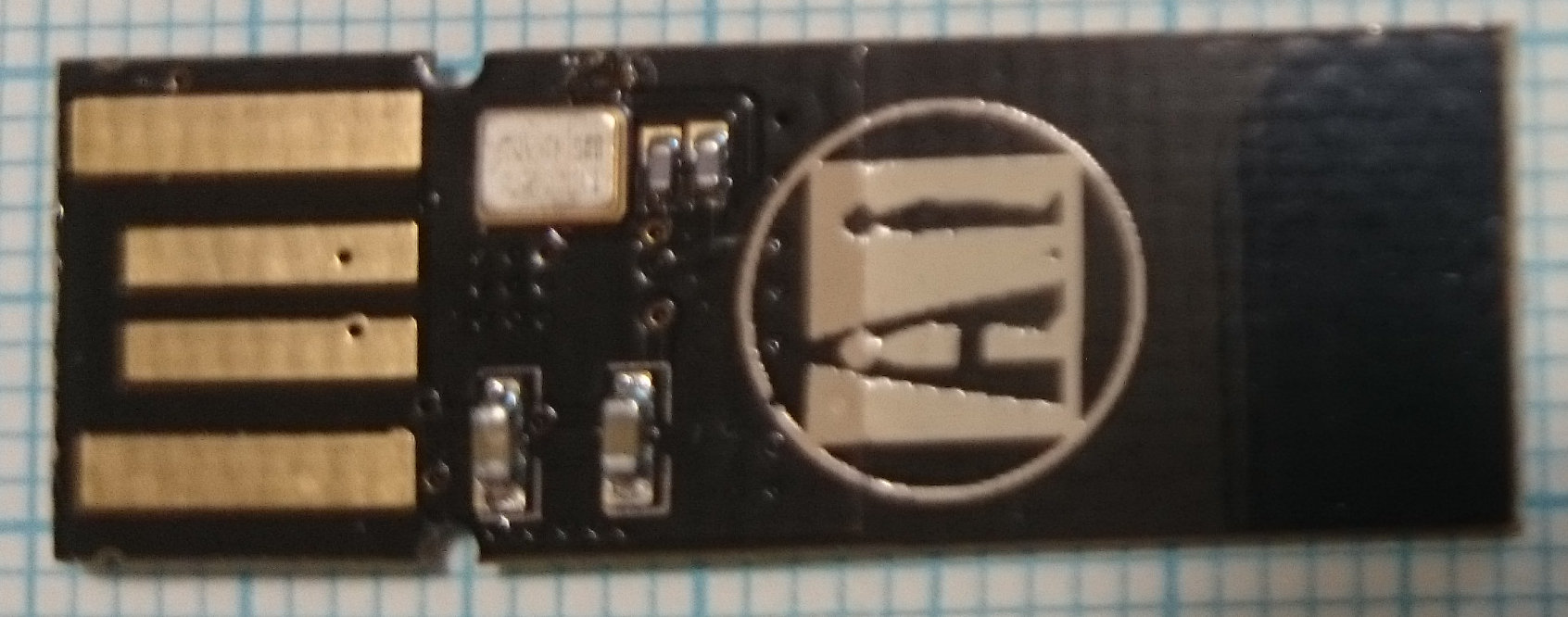
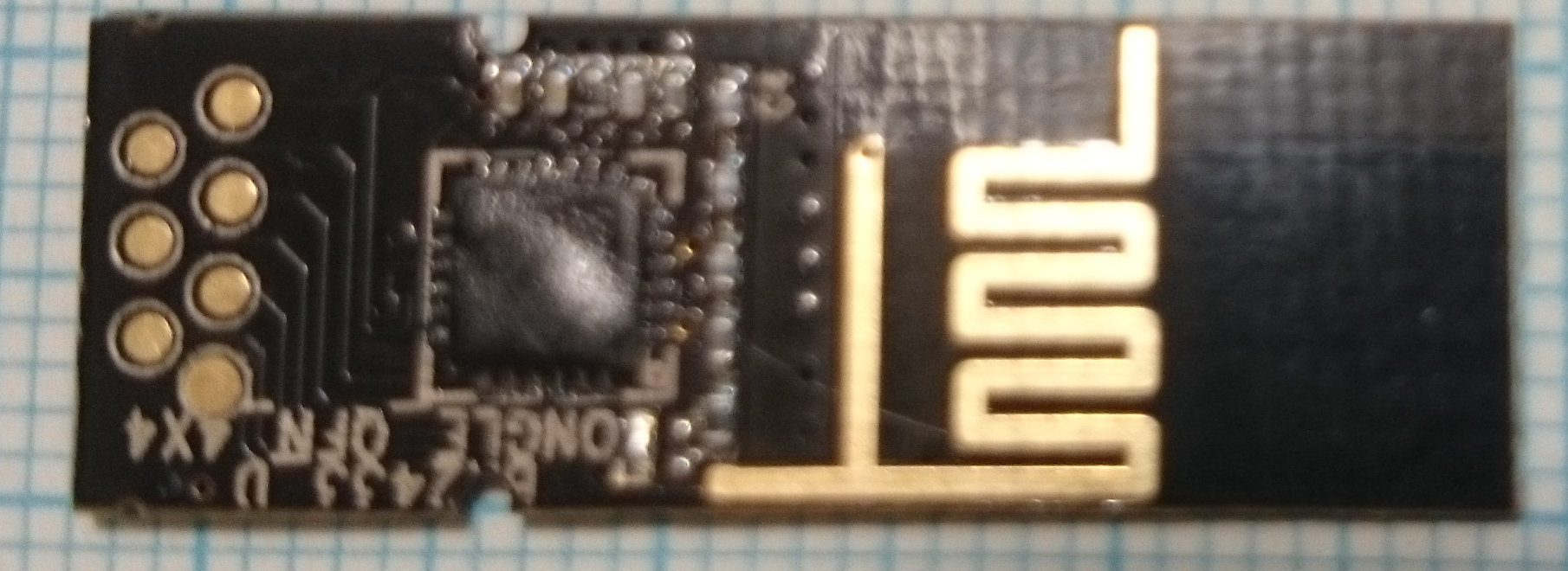
Sind inzwischen angekommen. Es handelt sich um USB-Stecker mit BK2433.
Das ist ein SOC mit 8051 und nRF24L01-Clone. Die Firmware emuliert eine
serielle Schnittstelle und nutzt die eingebauen Windows-Treiber. Es wird
nur ein Treiberdefinitionsfile benötigt (ini).

Ich habe eine geänderte .ini Datei angehängt, die das Dongle mit einem
englischen Namen registriert.

Das Dongle registriert sich als eine Serielle Schnittstelle mit 115200
baud und leitet die Daten transparent über 2.4Ghz weiter. Wenn man einen
no-nonsense Drahtlosen Terminalzugang braucht, ist das eine einfache
Lösung. Sogar noch stressfreier als die Bluetooth-Dongles.

Das Ändern der Frequenz (AT+SET?) habe ich leider nicht hinbekommen.
Evtl. muss man dafür noch einen Escape-Code senden.
Gast
#3722983
Hello, I don't speak German, but this is the only link I found yesterday
about those modules. It helped me, to find and dig the source, so I'll
post here my findings. This is a program I used to make them work with
arduino mega 2560 with RF24 library. I've included the comments in the
source, it should be easy to understand. I have no previous experience
before yesterday with these modules, so the things might be improved.
This program is an echo program, and should work out of the box.
To setup the Arduino and the nrf module I used the info here:
(http://arduino-info.wikispaces.com/Nrf24L01-2.4GHz-HowTo) with the
modification that CE pin goes to 48 and not 9
Hope you'll find it useful.


#include <SPI.h>
#include <RF24.h>
#include "nRF24L01.h"

RF24 radio(48,53); // CE pin and CSN pin

unsigned char ch;

void setup(void)
{
  Serial.begin(57600); //the usb dongle works by default at 1Mbit, so
this can be any speed
  radio.begin();

  //wi-fi channel (frequency) and the address and the speed
  // those are the default values, can be modified by user
  //
  // To modify them send the following text to the terminal on which the
usb dongle is: AT+SET=xxyyabcdefghij
  // xx is the channel
  // yy is the RF_SETUP REGISTER on nRF24l01 (on dongle there is BK2423,
but works almost the same)
  //        It sets the dB power level and the speed (default value 0x07
= 1Mhz, 0dB (maximum value));
  // ijghefcdab - the port (note that is in the reverse byte order)
  // all values are in hexadecimal
  // Example: to change to the default values use: AT+SET=28073443101001
  //
  radio.setChannel(0x28); //default value when the usb wifi dongle is
plugged (can be changed by user)
  radio.openReadingPipe(1,0x0110104334LL); //default value when the usb
wifi dongle is plugged (can be changed by user)
  radio.openWritingPipe(0x0110104334LL);
  radio.setDataRate(RF24_1MBPS);

  //setPayload,enabledynamic,setcrc.
  //These are hardcoded the same on usb wifi dongle.
  //Cannot be changed by the user
  radio.setPayloadSize(32);
  radio.enableDynamicPayloads();
  radio.setCRCLength(RF24_CRC_16);

  radio.startListening();
  radio.printDetails(); //print the configuration
}

void loop(void)
{
    if ( radio.available() )
    {
      radio.read( &ch, 1 );
      Serial.print((char)ch);
      radio.stopListening();
      //delay(5);
      radio.write(&ch,1);
      radio.startListening(); //flush the rx buffer
    }

}
Klaudyu schrieb:
> Hello, I don't speak German, but this is the only link I found yesterday
> about those modules.

Thank you very much! This is very useful indeed.

Did you ever manage to change the channel by using the AT commands?
Gast
#3732876
Tim wrote:
>Did you ever manage to change the channel by using the AT commands?

Yes, you just send the ASCII string to the device, it will automatically
intercept and configure the device (ex: "AT+SET=11073535353535" , where
3535353535 is the address, 11 is the channel - no quotes)
I used both TeraTerm and RealTerm, they both give the same result.
I've put the example on how to change in the comments of the program.
Gast
#3907308
Hello dear friend

I am using the following code.
But I could not establish a connection between the module NRF24l01+ and
the USB device.

If you could help me.
Thank you
1 | |
2 | |
3 | |
4 | |
5 | |
6 | |
7 | |
8 | |
9 | |
10 | |
11 | |
12 | |
13 | |
14 | |
15 | |
16 | |
17 | |
18 | |
19 | |
20 | |
21 | |
22 | |
23 | |
24 | |
25 | |
26 | |
27 | |
28 | |
29 | |
30 | |
31 | |
32 | |
33 | |
34 | |
35 | |
36 | |
37 | |
38 | |
39 | |
40 | |
41 | |
42 | |
43 | |
44 | |
45 | |
46 | |
47 | |
48 | |
49 | |
50 | |
51 | |
52 | |
53 | |
54 | |
55 | |
56 | |
57 | |
58 | |
59 | |
60 | |
61 | |
62 | |
63 | |
64 | |
65 | |
66 | |
67 | |
68 | |
69 | |
70 | |
71 | |
72 | |
73 | |
74 | |
75 | |
76 | |
77 | |
78 | |
79 | |
80 | |
81 | |
82 | |
83 | |
84 | |
85 | |
86 | |
87 | |
88 | |
89 | |
90 | |
91 | |
92 | |
93 | |
94 | |
95 | |
96 | |
97 | |
98 | |
99 | |
100 | |
101 | |
102 | |
103 | |
104 | |
105 | |
106 | |
107 | |
108 | |
109 | |
110 | |
111 | |
112 | |
113 | |
114 | |
115 | |
116 | |
117 | |
118 | |
119 | |
120 | |
121 | |
122 | |
123 | |
124 | |
125 | |
126 | |
127 | |
128 | |
129 | |
130 | |
131 | |
132 | |
133 | |
134 | |
135 | |
136 | |
137 | |
138 | |
139 | |
140 | |
141 | |
142 | |
143 | |
144 | |
145 | |
146 | |
147 | |
148 | |
149 | |
150 | |
151 | |
152 | |
153 | |
154 | |
155 | |
156 | |
157 | |
158 | |
159 | |
160 | |
161 | |
162 | |
163 | |
164 | |
165 | |
166 | |
167 | |
168 | |
169 | |
170 | |
171 | |
172 | |
173 | |
174 | |
175 | |
176 | |
177 | |
178 | |
179 | |
180 | |
181 | |
182 | |
183 | |
184 | |
185 | |
186 | |
187 | |
188 | |
189 | |
190 | |
191 | |
192 | |
193 | |
194 | |
195 | |
196 | |
197 | |
198 | |
199 | |
200 | |
201 | |
202 | |
203 | |
204 | |
205 | |
206 | |
207 | |
208 | |
209 | |
210 | |
211 | |
212 | |
213 | |
214 | |
215 | |
216 | |
217 | |
218 | |
219 | |
220 | |
221 | |
222 | |
223 | |
224 | |
225 | |
226 | |
227 | |
228 | |
229 | |
230 | |
231 | |
232 | |
233 | |
234 | |
235 | |
236 | |
237 | |
238 | |
239 | |
240 | |
241 | |
242 | |
243 | |
244 | |
245 | |
246 | |
247 | |
248 | |
249 | |
250 | |
251 | |
252 | |
253 | |
254 | |
255 | |
256 | |
257 | |
258 | |
259 | |
260 | |
261 | |
262 | |
263 | |
264 | |
265 | |
266 | |
267 | |
268 | |
269 | |
270 | |
271 | |
272 | |
273 | |
274 | |
275 | |
276 | |
277 | |
278 | |
279 | |
280 | |
281 | |
282 | |
283 | |
284 | |
285 | |
286 | |
287 | |
288 | |
289 | |
290 | |
291 | |
292 | |
293 | |
294 | |
295 | |
296 | |
297 | |
298 | |
299 | |
300 | |
301 | |
302 | |
303 | |
304 | |
305 | |
306 | |
307 | |
308 | |
309 | |
310 | |
311 | |
312 | |
313 | |
314 | |
315 | |
316 | |
317 | |
318 | |
319 | |
320 | |
321 | |
322 | |
Meine 2 cent:

Ich habe den stick mit einen Arduino Uno und nrf24l1+ getestet.

Mit diesen Programm:
https://github.com/maniacbug/RF24/blob/master/examples/pingpair_dyn/pingpair_dyn.pde

Es klappt ohne Probleme.
Den stick muss man mit: AT+SET=4C07E1F0F0F0F0 umstellen.
Bitte beachten dass es nur mit Großbuchstaben klappt.
4C ist die Default Frequenz vom nrf driver.
Die Adresse muss in umgekehrter Reihenfolge eingegeben werden.

Gruss Fredi
Angehängte Dateien:
-
 nrf-usb_ds.jpg
(190 KB)
nrf-usb_ds.jpg
(190 KB)
-
 nrf-usb_us.jpg
(200 KB)
nrf-usb_us.jpg
(200 KB)
Gast
#3960488
Und was bedeutet bei AT+SET=4C07E1F0F0F0F0 die 07?

Ich versuche gerade diesen Chinesen-Stick mit einem NRF24L01+ zu
verbinden, aber dieser empfängt nur kaputte Zeichen und es geht auch nur
in eine Richtung.

Gibt es noch weitere AT-Befehle? Oder eine Doku?